Trine 4100DBDL Installation Instructions
Open the original PDF document
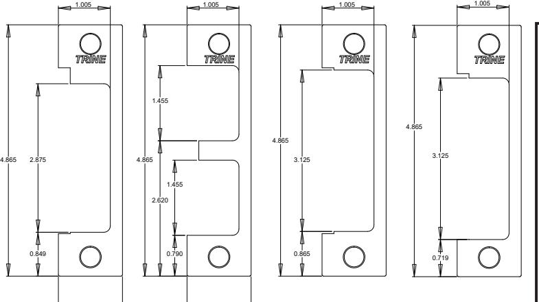
View PDFFLUSH TO FRAME
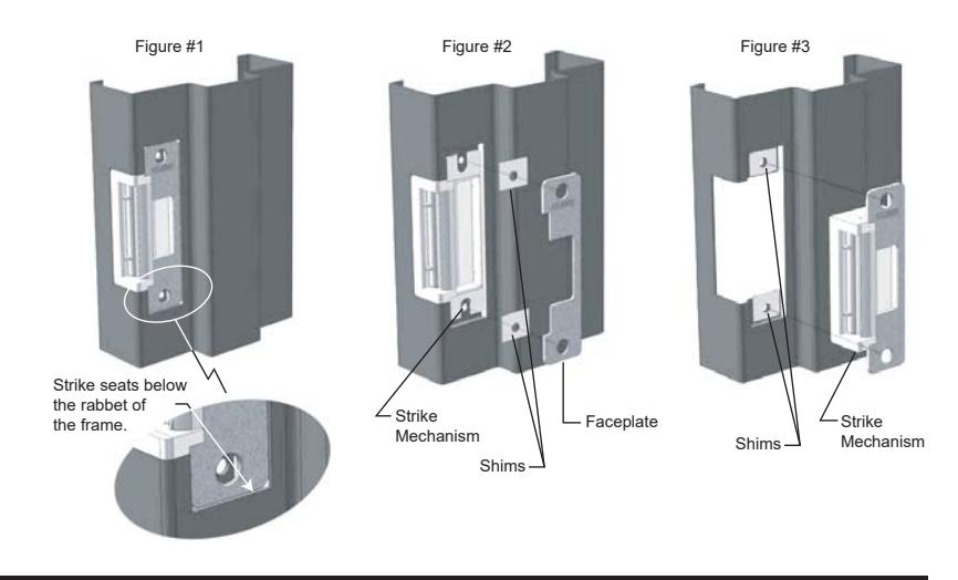
If the 4100DBDL electric strike does not mount flush to the rabbet of the frame, use the enclosed shims to correct this condition. There are two ways of mounting the shim; 1) between the strike mechanism and the faceplate as shown in figure #2 or 2) between the frame mounting tab and the strike mechanism as shown on figure #3.
TROUBLESHOOTING THE COMPLETED INSTALLATION:
DO NOT APPLY AN OVER VOLTAGE OF MORE THAN 10% OVER THE RATED OPERATING VOLTAGE OF THE STRIKE OR THE SOLENOID WILL BE DAMAGED
SYMPTOM: Electric release is not actuating:
- 1. Verify proper voltage is present AT THE STRIKE. If voltage is present, the strike may have been affected during the installation, or dirt or debris may be preventing proper operation. Ensure that all moving parts are clean. DO NOT LUBRICATE THE SOLENOID.
- 2. If voltage IS NOT present:
- · Verify Circuit breaker is on
- · Verify voltage at the transformer/power supply output.
- · Verify that there are no additional, external switches or devices which may be interrupting your circuit.
- · Check for damaged wiring or bad wire splices.
SYMPTOM: Door will not open but strike is working
- · First, check to see if the electric strike works properly while the door is open.
- · Check for proper lock-latch engagement
- · Check for pressure from the door on the electric strike by following these steps:
Push the door from the outside, try and relieve the bolt to latch pressure and actuate the 4100. While the 4100 is unlatched swing the door open. If the door opens, then the bolt maybe applying pressure to the latch. Adjust the position of the 4100 to relieve the pressure.
Possible remedies include:
- 1. Re-adjust door closer. 2. Remove door silencers.
- 3. Remove, or trim, weather stripping around the door. 4. Adjust electric strike position if possible.
- 5. Correct excessive warping of door.

PHONE: 203-730-1756 FAX: 203-730-1781 2 Parklawn Drive, Suite F Bethel, CT 06801
email: customerservice@trineonline.com website: www.trineonline.com
V. 17.0411
4
1.240
4100DBDL ELECTRIC STRIKE INSTALLATION INSTRUCTIONS
1.240

2 Parklawn Drive l Suite F l Bethel l CT l 06801
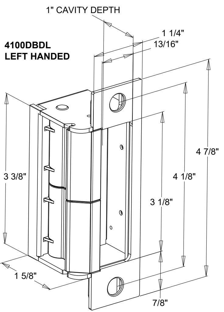
TRINE 4100DBDL
Congratulations on the purchase of this quality TRINE security product. This product has been designed to install easily, perform reliably, and provide years of trouble free security.
BEFORE PROCEEDING with your installation, please review the following list of features. If you have any questions after reading this document please call TRINE's TECHNICAL SUPPORT (203) 730-1756 EXT. 447, or visit the TRINE Web site at www.trineonline.com
The 4100DBDL is WH recognized for:
Class A, 3 Hour Single door / frame configuration

- UBC 7-2, Uniform building Code
- CAN4 S104, Standard Method for Fire Tests of Door Assemblies NFPA 252 -
Issue: 1999/01/01 Standard Methods of Fire Tests of Door Assemblies
NOTE: WH fire listing is void when using fail safe action.
ANSI/BHMA A156.5 - 1992 - 4-7/8" x 1-1/4" Fits Cutout Specification A115.1 (with Slight Jamb Modification) BHMA - Grade 1
4100DBDL ELECTRICAL CHARACTERISTICS:
| Current | Power | ||
|---|---|---|---|
| Voltage | Draw | Consumption | Resistance |
| 12DC | .240 A | 2.90 W | 50 Ω |
| 24DC | .114 A | 2.74 W | 210 Ω |
| 12AC @ 50-60Hz | .210 A | 2.50 W | 50 Ω |
| 16AC @ 50-60Hz | .281 A | 4.48 W | 50 Ω |
| 24AC @ 50-60Hz | .420 A | 10.08 W | 50 Ω |
NOTE: Volts/Amps for one (1) solenoid.
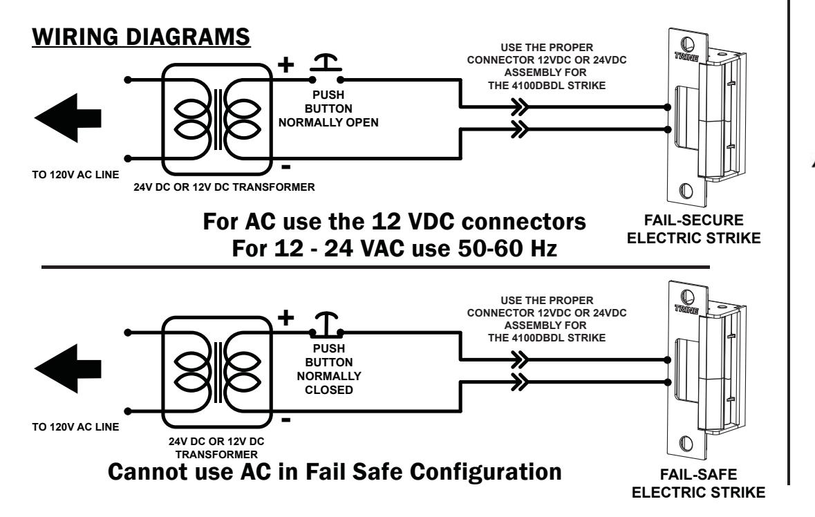
When removing the connector and using the wires direct; Red & Blue Wire accepts 12DC & 12-16 AC, Brown & Blue Wire accepts 24DC.
OPERATING TEMP RANGE: -20°C TO +40°C DO NOT APPLY AN OVER VOLTAGE OF MORE THAN 10% OVER THE RATED OPERATING VOLTAGE OF THE STRIKE OR THE SOLENOID WILL BE DAMAGED.
RECOMMENDED PRE-INSTALLATION CHECK:
- 1. Determine that the door swings without interfering with jamb or sill; the door must operate properly in
- order for the system to provide best results. 2. The door must be equipped with a door closer and the door closer "latch mode" must hold door in a completely closed position in order to avoid the lock latch from applying pressure against the releasing
- latch portion of the electric strike. 3. Electrical wire connections must be completed and
- ready to be terminated inside the frame. 4. Confirm that the power line in the frame is the
- correct voltage and that the switch works properly. 5. Confirm proper clearance exists between the end of the lock latch and jamb.
- 6. The faceplate opening used on the electric door strike must be centered with lock latch centerline when it is installed on the doorjamb.
- 7. For best installation results, the door frame must be reasonably flat and straight.
4100DBDL HOW TO ORDER/SPECIFY PART #'S
| BOTH LATCHES | 4100DBDL-RH-32D | ||
|---|---|---|---|
| FAIL SECURE | 4100DBDL-LH-32D | ||
| BOTH LATCHES | 4100DBDL-RS-RH-32D | ||
| FAIL SAFE | 4100DBDL-RS-LH-32D | ||
| TOP LATCH | 4100DBDL-RST-RH-32D | ||
| IS FAIL SAFE | 4100DBDL-RST-LH-32D | ||
| BOTTOM LATCH | 4100DBDL-RSB-RH-32D | ||
| IS FAIL SAFE | 4100DBDL-RSB-LH-32D | ||
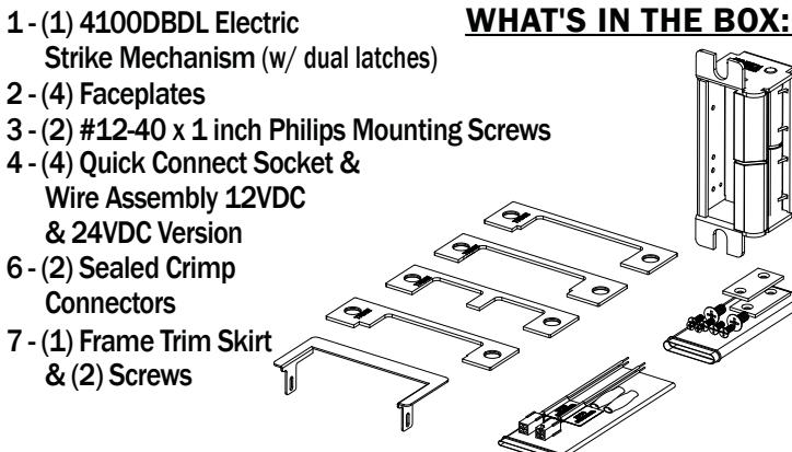
INSTALLING THE 4100DBDL STRIKE:
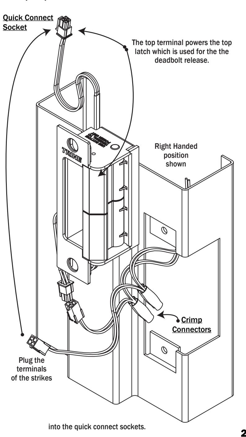
NOTE: The 4100DBDL electric strike has two terminal wires to supply power to two separate solenoids.
USE THE BOTTOM WIRE LEADS FOR THE MORTISE LATCH AND THE TOP WIRE LEADS FOR THE DEADBOLT.
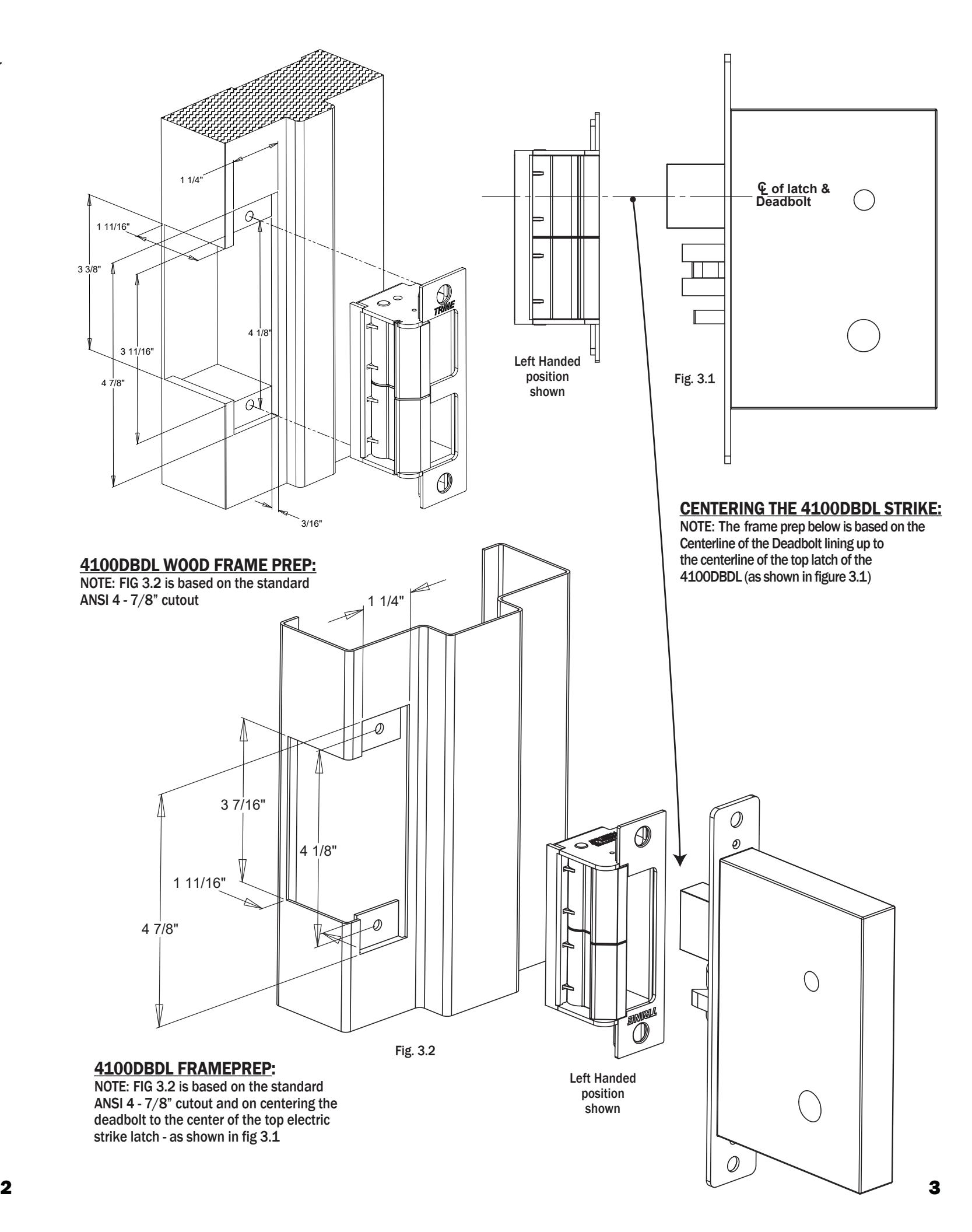
- 1. Prepare door frame as shown on page 2 (based on frame type).
- 2. Pull the switched power wires to the door frame. (Caution: Connect the power ONLY as the last step.)
- 3. Carefully choose the quick connect socket to match the required voltage. The quick connect sockets are labeled 12VDC (Blue Wire) or 24VDC (White Wire).
- 4. Use the crimp connectors to terminate the ends of the quick connect socket to the power wires coming out of the frame.
- 5. Connect the strikes bottom terminal to the quick connect socket.
- 6. Tuck the wires inside the door frame.
- 7. Install the electric strike into the door frame.
- 8. Connect the power supply and turn power on.
- 9. Test your system.