TMR9 Timer Off Delay Installation and Operating Instructions
Open the original PDF document
View PDF

SARGENT TMR9 MODELS TM-9 INSTALLATION AND OPERATING INSTRUCTIONS
1. DESCRIPTION
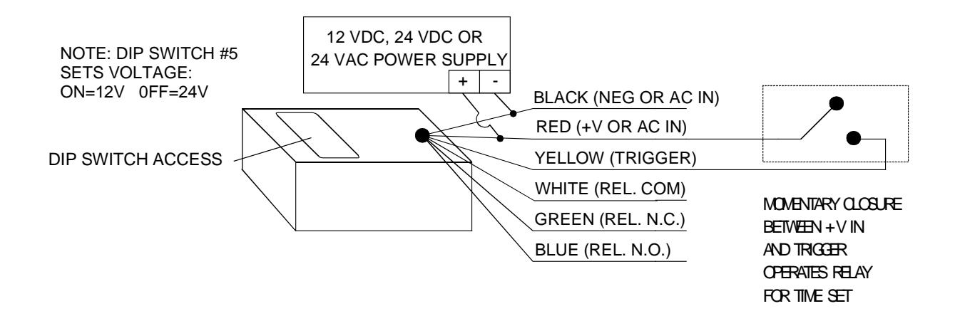
The TMR9 is a miniature " off delay " timer which operates on 12 VDC, 24 VDC or 24 VAC and provides a digitally set delay time of up to 35 seconds. The TMR9 has a 3 Amp SPDT relay output. When the trigger wire (YELLOW) is closed to the +V input (RED), the relay energizes. As long as the trigger wire is receiving +V, the relay remains energized but timing does not begin. When +V power is removed from the trigger wire, the relay remains energized until the set time expires (off delay function). At that point, the relay deenergizes until the next trigger operation. Note that the TMR9 is retriggerable . This means that if the trigger wire receives power in the middle of a timing operation, the relay stays energized while the previous timing cycle halts. When power is removed from the trigger, a new timing cycle begins. As long as trigger events keep occurring prior to a cycle timing out, the relay stays energized.
The most common application for the TMR9 is as a " pulse extender ". There are many situations where a momentary manual switch closure is used to control a device and also where the operation must be extended for an amount of time. Operation of the switch activates the TMR9, whose relay then engages or releases the device for up to 35 seconds. It is as if the switch was held for that amount of time.
A common application is to have a keyswitch or push button mounted in an outlet box whose function it is to release an electric lock . Without the TMR9, use of the door is a 2 handed operation. The switch is operated with one hand and the door is pushed open with the other. When the TMR9 is added, momentarily operating the switch releases the lock for enough time for a person to conveniently move through the door.
Integration with an outlet box mounted switch is the reason for the TMR9 being packaged in a miniature plastic box. In most cases, the TMR9 can be installed in the outlet box with the switch. Alternately, the TMR9 may be mounted on the rear, top or side of the outlet box using the supplied double stick tape.
2. OPERATION AND WIRING
The TMR9 requires 12 VDC, 24 VDC or 24 VAC for operation. It will not operate on 12 VAC. It draws no current when "at rest" and 27 mA @ 12v or 38 mA @ 24v when the unit is timing. It is most convenient to operate the TMR9 on the same power supply that operates the electric lock or other load. DC voltage need not be regulated (transformer + bridge rectifier is acceptable.)
Voltage selection and time setting are all accomplished by use of the five dip-switches which are accessible on the unit. Dip-switch #5 selects the voltage: ON=12V; OFF=24V . Be sure you set this switch correctly as the unit will be damaged if it is set for 12 volts and operated on 24.
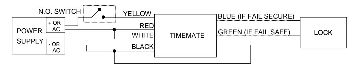
Four drawings are shown on the other side of this sheet. The first shows general operation of the unit which is valid for a broad range of uses. The second shows wiring for control of electric locks. Note that you use the blue or green wire for lock hookup depending on whether the lock is fail secure (released when energized) or fail safe (secure when energized). Note also that this connection is valid only when the same power supply operates the TMR9 and lock.
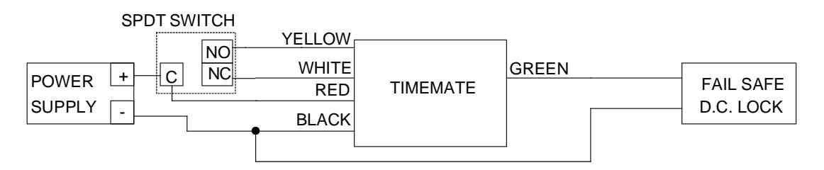
The third drawing shows a more reliable way of wiring DC fail safe locks. We call this "double break" wiring. It does require the use of an SPDT switch as the drawing shows. Power to the lock is routed through the switch's NC contacts as well as through the TMR9's NC relay contacts. When the TMR9 is triggered from the switch's NO contacts, the relay breaks power to the lock. The switch itself also breaks power to the lock which is why this connection procedure is called "double break". The advantage is that should the timer fail for any reason, the door can still be released from the switch for 2 handed exit until the timer can be replaced.
The fourth drawing shows time setting. Note the five position dip switch. Be sure you can identify the ON/OFF state of each switch. ON is towards the numbers. Switches 1-4 can be set in 16 different combinations (matrixes) which yield 16 different delay times, in seconds, as are shown in the chart. The factory set value is 5 seconds which is displayed in the drawing. Note that actual time can vary by about 10% from the "nominal" time which is displayed, so test the unit prior to completing the installation. If it is "fast" or "slow", you can choose the adjacent Dip Switch Matrix setting to yield the exact time you require.
TIMEMATE: GENERAL OPERATION
TIMEMATE: 12 VDC, 24 VDC OR 24 VAC ELECTRIC LOCK CONTROL
TIMEMATE: DOUBLE BREAK WIRING FOR FAIL SAFE DC LOCK
TIMEMATE: DIGITAL TIME SETTING
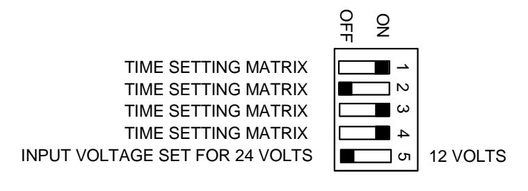
NOTE: FACTORY SET 5 SECOND DELAY IS SHOWN IN DRAWING
| ON | ON | ON | ON | 2 |
|---|---|---|---|---|
| OFF | ON | ON | ON | 4 |
| ON | OFF | ON | ON | 5 |
| OFF | OFF | ON | ON | 7 |
| ON | ON | OFF | ON | 12 |
| OFF | ON | OFF | ON | 15 |
| ON | OFF | OFF | ON | 16 |
| OFF |
OFF
OFF |
OFF
OFF |
ON
ON |
16
18 |
| • • • | ||||
| OFF | OFF | OFF | ON | 18 |
|
OFF
ON |
OFF
ON |
OFF
ON |
ON
OFF |
18 |
OF
OFF
30
32
34 36
ON
OFF
ON
ON
SW#1 SW#2 SW#3 SW#4 TIME
SARGENT Manufacturing Company • 100 Sargent Drive • P.O. Box 9725 • New Haven • CT 06536-0915 Phone: 800-727-5477 • Fax: 888-863-5054 • Web site: www.sargentlock.com
Founded in the early 1800's, SARGENT® is a market leader in locksets, cylinders, door closers, exit devices, electro-mechanical products and access control systems for new construction, repoyation, and replacement applications. The company's customer base includes commercial construction, institutional, and industrial markets.
© SARGENT Manufacturing Company 2007
ASSA ABLOY is the global leader in door opening solutions, dedicated to satisfying end-user needs for security, safety and convenience.