TL- SARGuide Illuminated Touchpad Installation Instructions for 80 Series Exit Devices
Open the original PDF document
View PDFInstallation and Wiring Instructions for the TL- Prefix SARGuide Illuminated Touchpad for 80 Series Exit Devices to ElectroLynx™ Connector System

ASSA ABLOY
U.S. Patent No. 7,204,050
For assistance, contact SARGENT at 800-810-WIRE (9473) or www.sargentlock.com
A. Function
The SARGuide exit device contains an illuminated touchpad to enhance the visibility of exit locations in dark or smoke-filled passages and is intended as a supplement to existing codes for egress lighting.
B. Important
- 1. Caution: Disconnect all input power before beginning installation to prevent electrical shock and equipment damage.
- 2. Installer must be a trained, experienced service person.
- 3. All wiring must comply with applicable local electrical codes, ordinances and regulations.
C. ElectroLynx Connector System Notes:
The system is designed to be installation friendly with connectors from the electric hinge through the door to the rail. The only wiring required is to the loose wires on the pigtail harness assembly on the frame side of the electric hinge.
IMPORTANT:
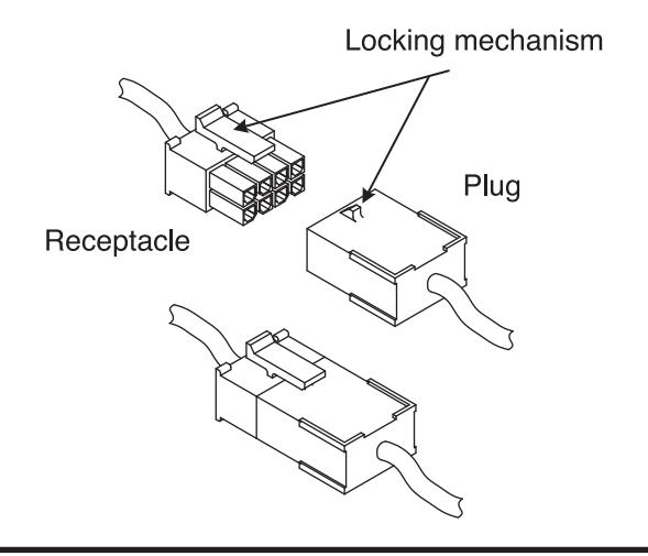
The plug and receptacle connectors are designed to mate and lock together as shown in the figure. Plug the connectors into each other with the locking mechanism aligned as indicated.

D. Installation Notes
- 1. With new applications, a raceway harness with 8 & 4-pin connectors will be pre-installed inside door by ASSA ABLOY door manufacturer when specified during ordering process. Raceway harness kits are also available for retrofit applications. For retrofit applications, refer to retrofit instructions.
- 2. If door does not have a raceway harness with connectors, either consult factory for raceway retrofit kit, or cut the connectors off product and hard wire as required.
- 2. Wiring to pigtail harness is per facility wiring requirement. The rail, raceway, electric hinge and pigtail connector terminations and wire colors all match.
E. TL- SARGuide Exit Device Installation
SARGENT

- 1. Mount exit device per instruction sheet provided.
-
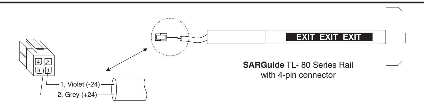
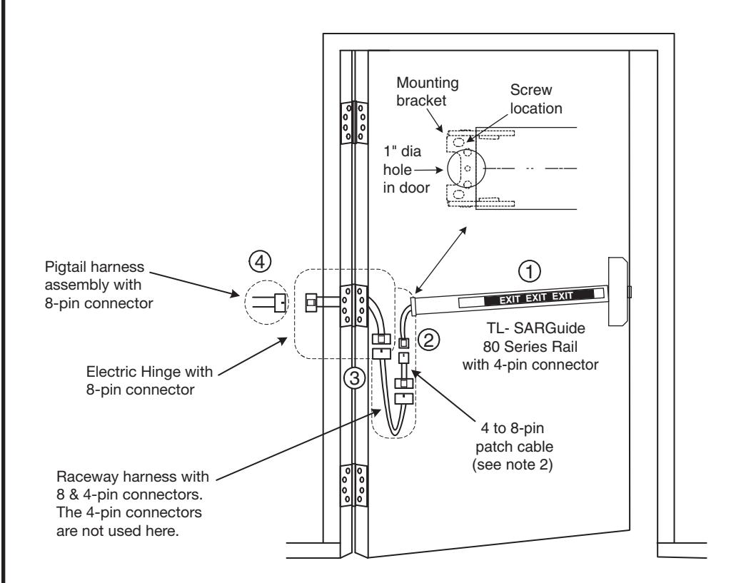
2. TL- (SARGuide) only <u>without</u> other rail wiring requirements Install 4 to 8-pin patch cable between the rail and raceway connectors.
- TL- (SARGuide) with other rail wiring requirements Do NOT install 4 to 8-pin patch cable.
Refer to the wiring diagrams on the following pages.
If additional electrical functions exist, plug rail 8 & 4-pin connectors into raceway connectors. Feed harnesses through 1" hole in door. Install rail mounting bracket with two screws supplied. Install rail insert and end cap.
To insure trouble free operation, check that the push rail can be fully depressed. On vertical rod exit devices, adjust rods and check that the latch bolts do not go into hold back position until the push rail is fully depressed.
- 3. Plug raceway connector(s) into electric hinge connector(s), then feed through door prep. Mount electric hinge to door.
-
4. Go to (A) if wiring now. Go to (B) if wiring is to be done later.
- A. Refer to wiring examples. Wire loose frame side wires to loose wires on pigtail harness as required, using connectors allowed by local code. Plug pigtail harness connector(s) into electric hinge connector(s). Feed harnesses through frame prep and mount electric hinge. Apply power and test exit device
- B. Plug pigtail harness connector(s) into electric hinge connector(s). Feed harnesses through frame prep and mount electric hinge.
F. TL- SARGuide Wiring Examples
SARGENT
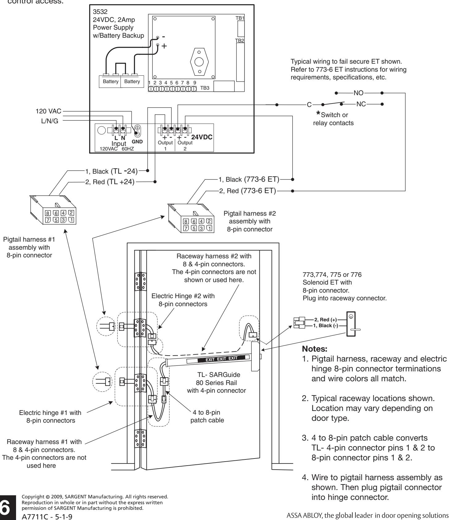
Sample Wiring #1 – TL- Prefix SARGuide and 3532 Power Supply and Battery Back-up
ASSA ABLOY
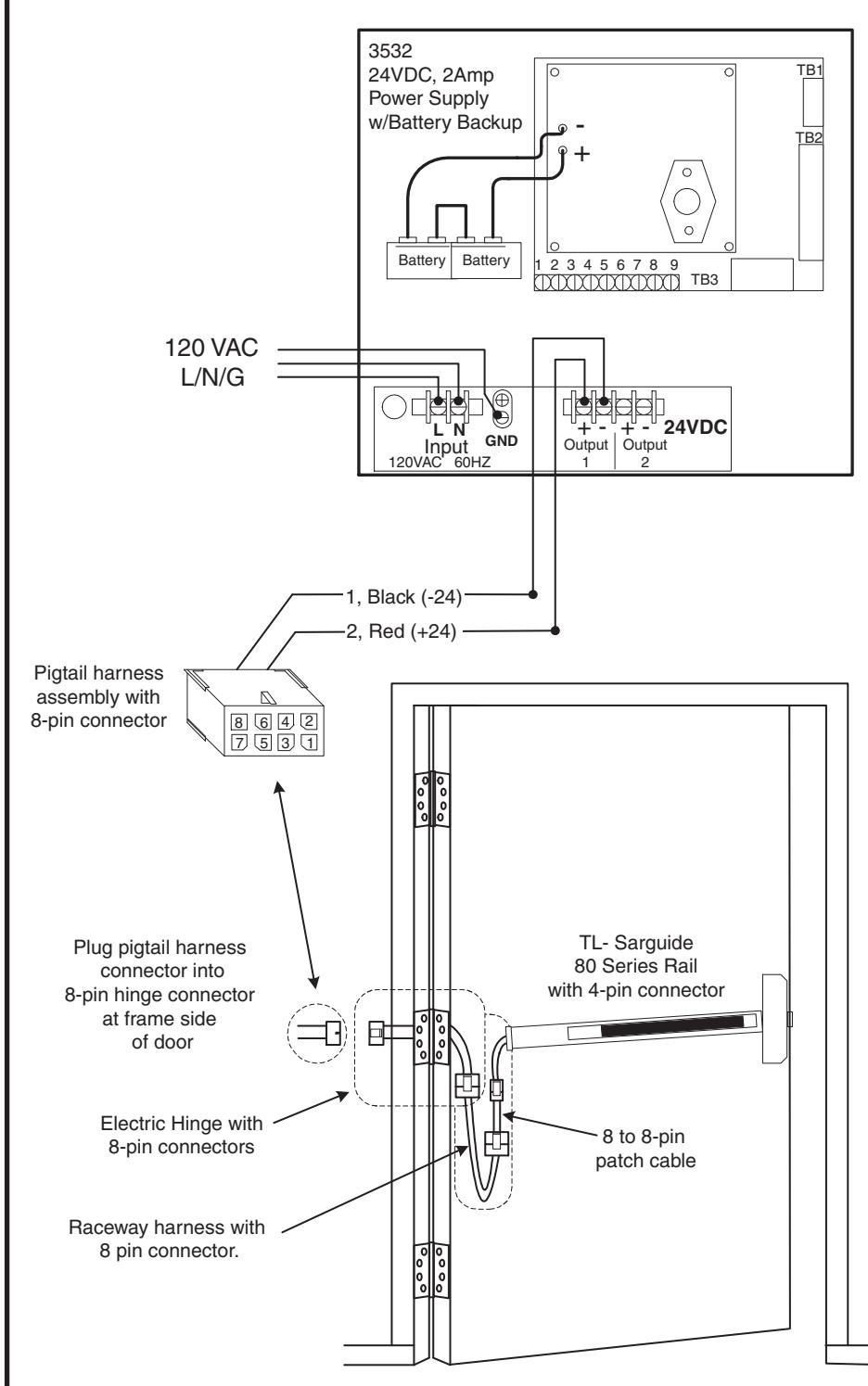
System Description:
SARGuide is always powered. During a power outage SARGuide remains powered and illuminated by 3532 battery back-up power.
Notes:
- TL- SARGuide power requirement: Input Power: 24VDC/VAC Current draw: 30mA
- Pigtail harness, raceway and electric hinge 8-pin connector terminations and wire colors all match.
- 3. 4 to 8-pin patch cable converts TL- 4-pin connector pins 1 & 2 to 8-pin connector pins 1 & 2.
- 4. Wire to pigtail harness assembly as shown then plug pigtail connector into hinge connector.
F. TL- SARGuide Wiring Examples cont'd
SARGENT
Sample Wiring #2 – TL- (SARGuide) with 12- 58- (Electric Dogging) combination and 3532 Power Supply with Battery Back-up. 53-, 55- wiring if required.
ASSA ABLOY
80 series rail prefixes 53- latch bolt monitor swicth
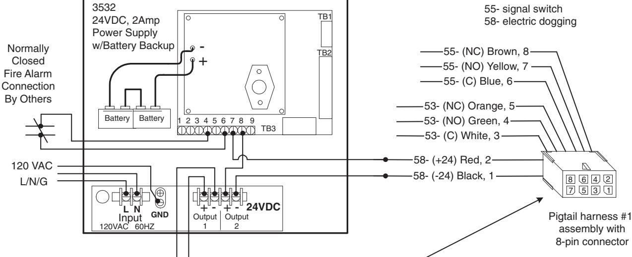
System Description:
SARGuide is always powered. During a power outage SARGuide remains powered and illuminated by 3532 battery back-up power.
Fire Rated Operation:
If using 12-58- Electric Dogging in conjunction with SARGuide, a normally closed fire alarm contact (by others) must be used and must be wired as shown.
Notes:
- TL- SARGuide power requirement: Input Power: 24VDC/VAC Current draw: 30mA
- 2. Pigtail assemblies, electric hinge, raceway and rail connector terminations and wire colors all match.
- 3. For 53, 55- and 58- wiring also refer to individual product instructions provided. Wire as required by rail type used.
F. TL- SARGuide Wiring Examples cont'd
SARGENT
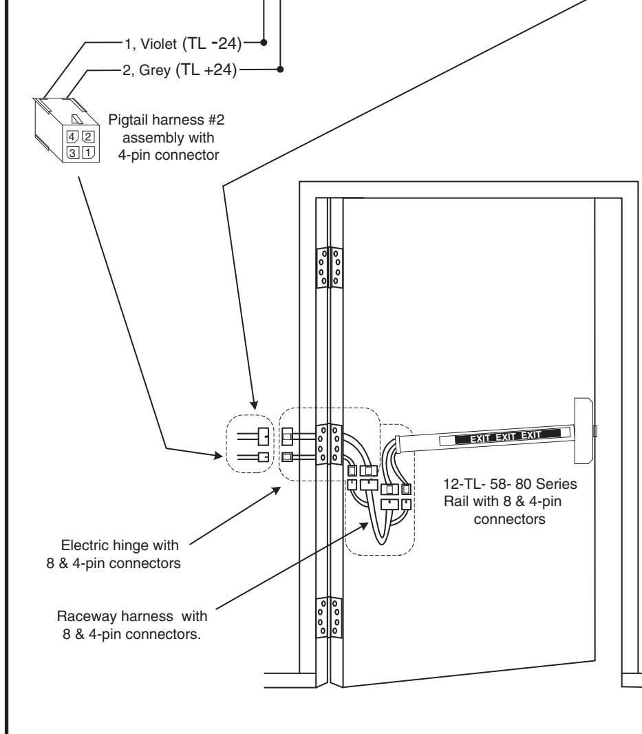
Sample Wiring #3 – TL- (SARGuide) with 57- (Delayed Egress) combination and 3532 Power Supply with Battery Back-up.
ASSA ABLOY
F. TL- SARGuide Wiring Examples cont'd
SARGENT
Sample Wiring #4 - TL- Prefix (SARGuide) with Solenoid Exit Trim (ET) and 3532 Power Supply and Battery Back-up
ASSA ABLOY
SARGuide is always powered. During a power outage SARGuide remains illuminated by 3532 battery back-up power. The 3532 power supply also provides battery back-up power to the solenoid exit trim (ET), which is used to control access.