TDC70 Installation
Open the original PDF document
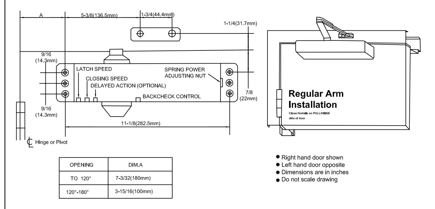
View PDFInstallation Instructions for REGULAR ARM (PULL SIDE) Mounting
INSTALLATION INSTRUCTIONS
- 1.Select degree of opening from table and use template dimensions shown in above, mark six(6)holes on door for door closer and two(2) holes on frame for arm shoe.
- 2. Drill pilot holes in door and frame for #14 all-purpose screws or drill and tap for 1/4-20 machine screws.
- 3. Install adjustable forearm/shoe assembly to frame using screws provided.
- 4.Install main arm to top pinion shaft using screw provided.
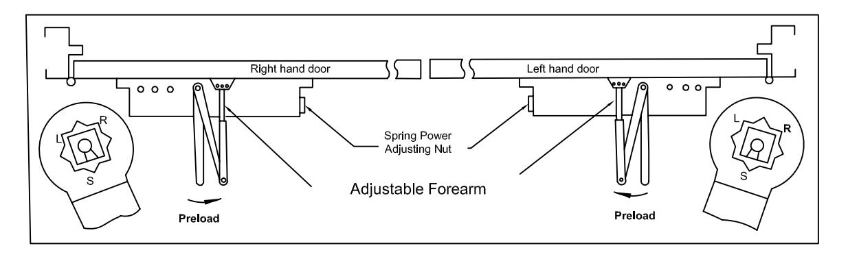
- 5. Mount closer on door using screws provided. SPRING POWER ADJUSTING NUT MUST BE POSITIONED AWAY FROM HINGE EDGE.
- 6. Adjust length of adjustable forearm so that adjustable forearm is perpendicular to frame when assembled
- 7. Snap pinion cap over shaft at bottom of closer (When using full cover pinion cap is not necessary).
- 8. Adjust closing speed, back check control and spring power of door, following instructions as shown on p4.
Top View Typical Installation
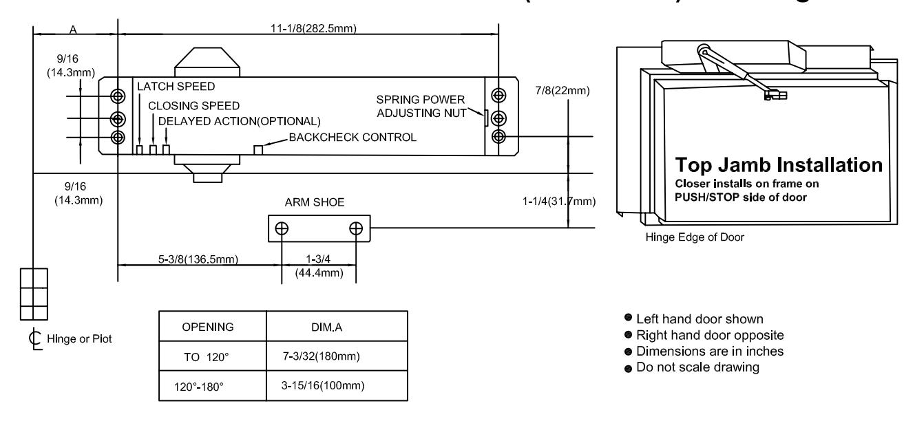
Installation Instructions for TOP JAMB (PUSH SIDE) Mounting
INSTALLATION INSTRUCTIONS
- 1.Select degree of opening from table and use template dimensions shown in above, mark SIX(6) HOLES ON FRAME for closer and TWO(2) HOLES ON DOOR for arm shoe.
- 2.Drill pilot holes in door and frame for #14 all -purpose screws of drill and top for 1/4-20 machine screws.
- 3.Install adjustable forearm/arm shoe assembly to door using screws provided.
- 4.Install main arm to top pinion shaft using screw provided.
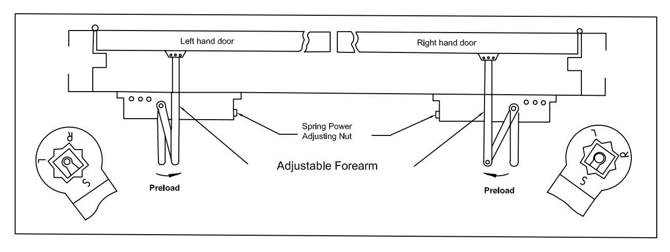
- 5.Mount closer body on frame using screw provided, SPRING POWER ADJUSTING NUT MUST BE POSITIONED AWAY FROM HINGE EDGE.
- 6.Adjust length of adjustable forearm so that adjustable forearm is perpendicular to door when assembled to preloaded main arm (illustration below). Secure forearm to main arm with screw provided.
- 7. Snap pinion cap over shaft on top of closer. (When using full cover, pinion cap is not nessary)
- 8.Adjust closing speed, backcheck control and spring power of door, following instructions as shown on p. 4.
Top View Typical Installation
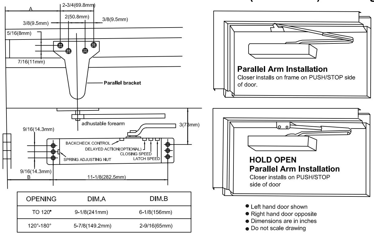
Installation Instructions for PARALLEL ARM (PUSH SIDE) Mounting
INSTALLATION INSTRUCTIONS
- 1. Select degree of opening from table and use template dimensions shown in above, mark six(6) holes on door for door closer and four(4) holes underside of frame for bracket.
- 2.Drill pilot holes in door and frame for #14 all-purpose screws or drill and tap for 1/4-20 machine screws.
- 3.Mount closer on door using screws provided. SPRING POWER ADJUSTING NUT MUST BE POSITIONED TOWARD HINGE EDGE.
- 4.Install parallel Arm Bracket to frame using screws provided.
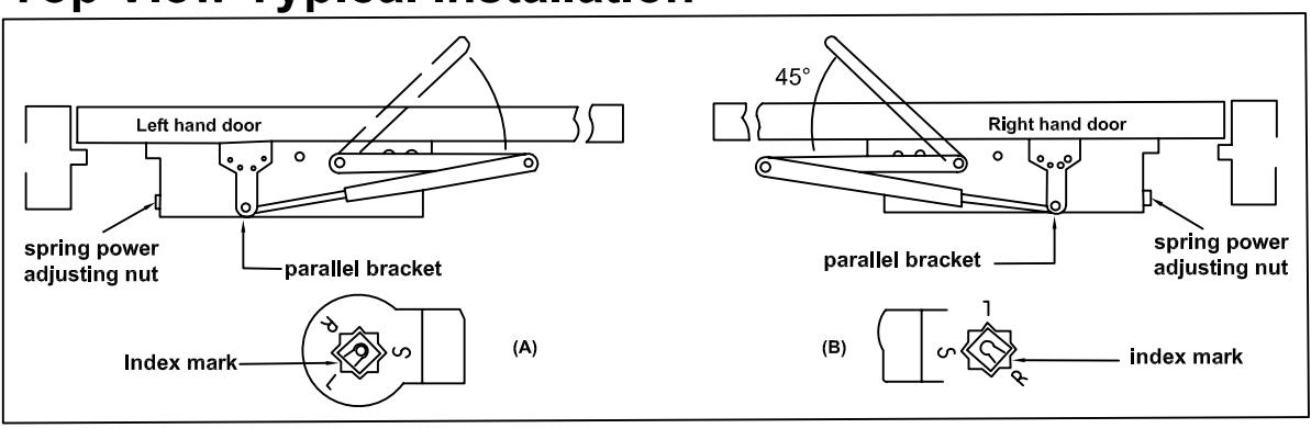
- 5.Using a wrench on the square shaft at bottom of shaft on top of closer, rotate shaft approximately 45° to ward hinge edge of door. Hold and place main arm of shaft on top of closer at proper index mark as illustrated.
FOR LEFT HAND DOOR "L"(illustration "A").FOR RIGHT HAND DOOR "R" (illustration "B").Tighten arm screw with lockwasher securely.
- 6. Remove arm shoe from the forearm and discard (arm shoe is not used for paralled installation) and tighten screw securely.
- 7. Adjust length of adjustable forearm so that adjustable forearm is parallel to frame.
- 8. Snap pinion cap over shaft at bottom of closer (when using full cover, pinion cap is not necessary)
- 9. Adjust closing speed, backcheck control and spring power of door, following instructions on page 4.
Top View Typical Installation
CLOSER ADJUSTMENT
CLOSING CYCLE
NOTE:Closing arcs ("CLOSE" and "LATCH") are controlled by two (2) speed adjusting valves adjust the CLOSING speed first, then adjust the LATCHING speed.
- 1."CLOSING"speed adjustment is accomplished by full rotations of the speed adjusting valve.
- -Turn the speed adjusting valve CLOCKWISE for a SLOWER CLOSE arc closing speed.
- -Turn the speed adjusting valve COUNTER-CLOCKWISE for a FASTER CLOSE arc closing speed .
-
2."LATCH"speed adjustment is accomplished by full rotations of the speed adjusting valve.
- -Turn the speed adjusting screw CLOCKWISE for a SLOWER Latch arc closing speed.
- -Turn the speed adjusting screw COUNTER-CLOCKWISE foa a FASTER Latch arc closing speed.
CAUTION!! Do not turn speed adjusting more valve than two(2) full turns counter-clockise from its factory set position, as two speed adjusting valves could become dislodged from the door closer body, resulting in the loss of internal fluid and failure of the device.
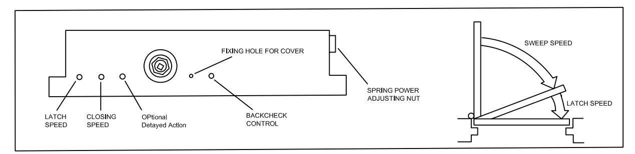
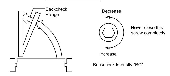
BACK CHECK CONTROL
To increse back check intensity, turn back check control valve clockwise.
To decrease back check intensity, turn back check control valve counter-clockwise.
SPRING POWER CONTROL
To increase opening force and closing force, turn the spring adjusting nut clockwise.
To decrease opening force and closing force, turn the spring adjusting nut counter-clockwise.
FULLY ADJUSTABLE SPRING
900SERIES CLOSERS ARE SHIPPED AS SIZE 3. ROTATE SPRING ADJUSTMENT NUT COUNTER-CLOCKWISE 3 TURNS TO REDUCE TO SIZE 2. ROTATE SPRING ADJUSTMENT NUT CLOCKWISE TO INCREASE SPRING POWER. MAXIMUM 10 TURNS TO ATTAIN SIZE 6.
| CLOSER SIZE | CLOCKWISE | |
|---|---|---|
| BC/DA 🕏 | BF 5 |
TURNS OF
ADJUSTING NUT |
| 1 | 1/2 | -3* |
| 2 | 1 | 0 |
| 3 | 2 | 3 |
| 4 | 3 | 6 |
| 5 | 4 | 9 |
*-3=3 TURNS COUNTERCLODKWISE
OPENING CYCLE
ADJUSTABLE SPRING MODELS
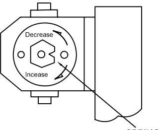
SPRING ADJUSTMENT NUT
NOTE:MAXIMUM ADJUSTMENT IS APPROXIMATELY 10 TURNS. DO NOT FORCIBLY EXTEND ADJUSTMENT BEYOND LIMITS.