Simplex LP1000 Resetting the Code
Open the original PDF document
View PDFResetting the Code/Combination From a Lost Code Simplex LP1000
Important: There is no procedure for finding an unknown combination from the front of the lock. A lost combination must be cleared by removing the combination chamber from the lock housing, then a new combination can be set.
LP1000 Series FAQ Resetting the Code/Combination From a Lost Code
- 1. Remove the back plate from the front lock housing by removing the six back plate screws.
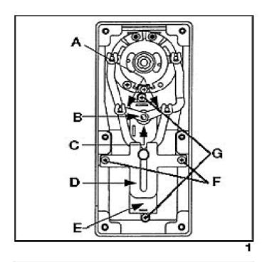
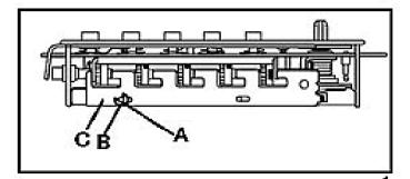
- 2. Remove the two Phillips head screws (F) securing the guide bracket (D to the front housing. Grasp the guide bracket and slide it back to disengage it from the clutch linkage (see figure 1) .
- 3. Lift the two chamber links (A) off of the control shaft (B) using a small flat blade screwdriver. Mark links to assure proper reassembly (see figure 1) .
-
4. Remove the combination chamber (E) by removing the Phillips head screws (G) at each end of the chamber
(see figure 1)
.
- 5. Remove shaft bushing (C) from control shaft (see figure 1) .
-
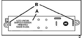
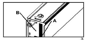
6. Remove chamber cover marked ILCO UNICAN (A) (see figure 2) by gently tapping the lip of the chamber cover (A) at the control shaft end of the chamber
(see figure 3)
with a screwdriver to detach it from the staked joints (B).
- 7. Lay the chamber on its side as shown in figure 4.
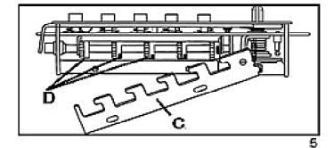
- 8. With tweezers, or other tool, slide the "E" ring (B) off the unlocking slide stud (A) (see figure 17-4), then gently lift the end of the unlocking slide (C) over the unlocking slide stud (A) (see figure 5) .
Note: The unlocking slide (C) is under spring tension and will be easier to lift if pushed to the left to ease tension. Swing the unlocking slide (C) sufficiently to clear the gears, (D) no further than shown in figure 5.
- 9. Depress the lockout slide (E) as shown in figure 6. The gears (D) are now free to rotate.
- 10. Turn each gear (D) so that the slots (F) are aligned as shown in figure 6.
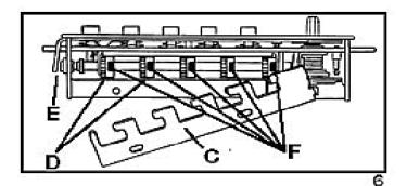
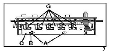
11. Return the unlocking slide (C) over the unlocking slide studs (A) while making certain the five toes (G) are engaged in the five gear pockets (F). It may be necessary to adjust each gear (D) slightly to make proper alignment between toes and gear slots (see figures 6 & 7) . Re-secure the "E" ring on the stud (A). Your chamber will now resemble figure 7 and is ready for reassembly with the lock housing.
REASSEMBLY
-
1. Re-secure the chamber cover (A) marked ILCO UNICAN. Make sure the staked joints (B)
(see figure 2
) on both end plates fit through both slots on the chamber cover.
- 2. Re-secure the shaft bushing (C) with flat side facing up (see figure 8) .
- 3. Secure the combination chamber with the two Phillips head screws (G) you removed earlier.
- 4. Re-secure the chamber links (A) onto the control shaft.
-
5. Replace the guide bracket (D) by aligning the clutch linkage in the guide bracket and secure with the two Phillips head screws (F) previously removed.
- 6. Replace the back plate and secure it with the six back plate screws.
SETTING THE COMBINATION
Do not attempt to set a combination until the complete unit has been reassembled. Perform the following steps in the order shown.
- 1. Turn the outside lever once to the stop position and then release.
- 2. Enter the new combination.
- 3. Turn the outside lever to the stop position, make sure the latch is fully retracted, then release the lever.