Simplex LD470 Installation Instructions
Open the original PDF document
View PDF
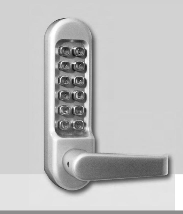

Pushbutton Lock Installation Instructions LD470
TABLE OF CONTENTS
| Checklist | .3 | |
|---|---|---|
|
Operational
Note |
.3 | |
|
Determining
the Hand of Your Door |
.4 | |
| A. |
Changing
the Door Handing |
.4 |
| B. |
Marking
the Template and Drilling the Door |
.5 |
| C. |
Installing
the Latch |
.5 |
| D. |
Installing
the Spindle |
.6 |
| E. |
Installing
the Lock |
.6 |
| F. |
Installing
the Strike Plate |
.7 |
| G. |
Changing
the Code |
.8 |
| H. |
Using
the Passage Function |
.9 |
| I. |
Removing
the Passage Function |
.9 |
| J. |
Trouble
Shooting |
.10 |
Warnings and Cautions
Important : Carefully inspect windows, doorframe, door, lights, etc. to ensure that the recommended procedures will not cause damage. Kaba Access Control's warranty does not cover damages caused by installation.
Caution : Wear safety glasses when preparing door.
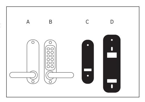
CHECKLIST
Use this checklist to make sure that everything has been included. ❏ ✔
- A— Outside unit
- B— Inside unit
- C— Gaskets (2)
- D— Universal trim plate (2)
- E— Spindles (3 lengths)
- F— Latch
- G— Strike plate
- H— Latch and strike screws (4)
- J— Tweezers
- K— Mounting screws (8) (4 lengths)
- L— Spare tumblers coded (2), uncoded (2)
- M— Code card
- N— Hex wrench
OPERATIONAL NOTE:
Prior to beginning installation, please check that all parts are working correctly. Press the "C" button 3-5 times. Enter the code from the factory supplied code card. Rotate the outside lever down and release. The lever should return easily under spring pressure. If you intend to change the code, you should do it before installing the lock (See Code Change Instructions).
Make sure that the inside lever moves freely.
Check that the latch bolt moves freely by pressing the bolthead at the end, and also by turning the flat spindle in the latch cam.

For technical assistance please call 1-800-849-TECH (8324) or 336-725-1331
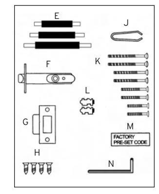
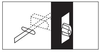
DETERMINING THE HAND OF YOUR DOOR
Many of the installation instructions refer to the handing of your door. The hand of the door is determined with the door in the closed position, from the exterior or pushbutton side of the door.
- A) Right Hand Door. Door opens inward (push). Hinged on the right side.
- B) Left Hand Door. Door opens inward (push). Hinged on the left side.
- C) Right Hand Reverse Door. Door opens outward (pull). Hinged on the right side.
- D) Left Hand Reverse Door. Door opens outward (pull). Hinged on the left side.
D All units are factory handed for right hand doors.
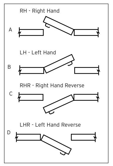
A. CHANGING THE DOOR HANDING
- A-1 For the outside unit assembly, remove the rubber plug from the outside lever, exposing the lever set screw.
- A-2 Using the hex wrench supplied, remove the set screw from the lever in question.
- A-3 Remove the lever and rotate it 180º. Slide the lever back onto the lock.
- A-4 Using the hex wrench supplied, reinstall the set screw. Assure the lever rotates freely.
- A-5 Reinstall the rubber plug, which was removed earlier.
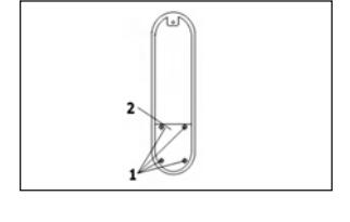
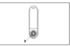
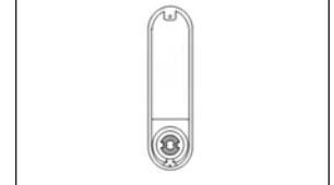
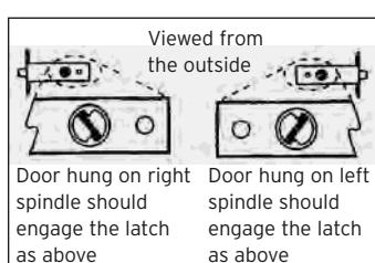
- A-6 For the inside unit assembly, turn the unit over so the back side is facing up.
- A-7 Remove the 4 screws securing the cover plate to the assembly. Then lift the cover plate and set aside.
- A-8 Lift the stop plate ring and position it according to the pictures to the right for this application.
- A-9 Resecure the cover plate using the 4 screws removed earlier.
- A-10 Remove the rubber plug from the inside lever, exposing the lever set screw.
- A-11 Using the hex wrench supplied, remove the set screw from the lever in question.
- A-12 Remove the lever and rotate it 180º. Slide the lever back onto the lock.
- A-13 Using the hex wrench supplied, reinstall the set screw. Assure the lever rotates freely.
- A-14 Reinstall the rubber plug, which was removed earlier.
B. MARKING THE TEMPLATE AND DRILLING THE DOOR
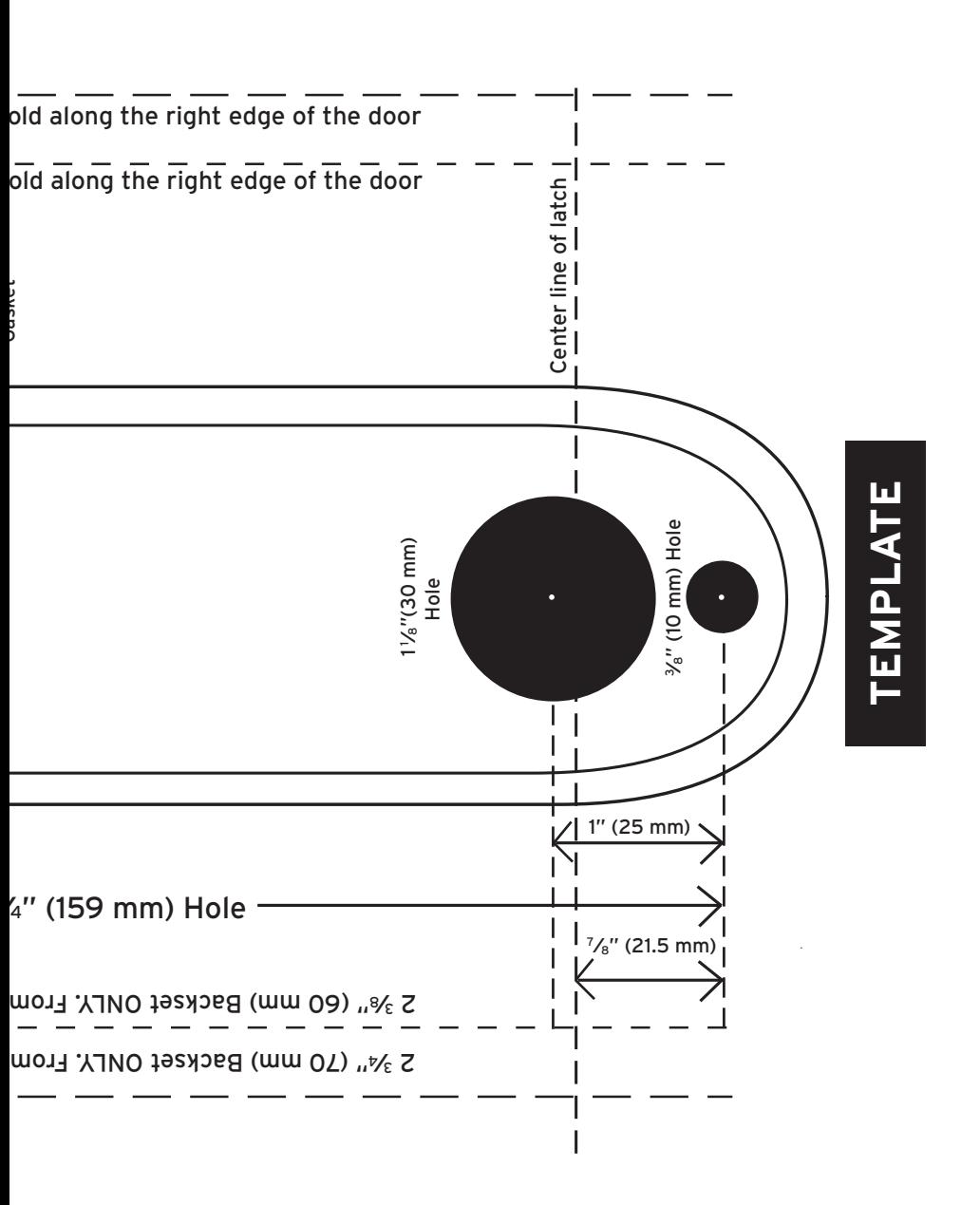
- B-1 Find and remove the template from the installation manual. Carefully fold along the dotted line that matches the backset the application requires.
- B-2 From the exterior (or push button side) of the door, place the dotted line of the template along the edge of the door.


C. INSTALLING THE LATCH
- C-1 Using the center line of the latch (marked on template), mark the point where the cross bore for the latch should be drilled.
- C-2 Drill a 1" (25 mm) diameter hole, 3 3⁄4" (96mm) deep, on that center point of the edge of the door.
- C-3 Insert the latch into the hole and outline the face of the latch (already prepped on most metal doors).
- C-4 Remove the latch.
- C-5 Using a chisel, remove the material 1 ⁄8" (3 mm) deep from the door for the faceplate of the latch (already prepped on most metal doors).
- C-6 Reinsert the latch and install the latch using the mounting screws provided.
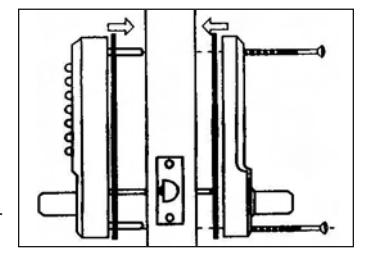
D. INSTALLING THE SPINDLE
Note : Assurance that the proper spindle is used is extremely critical. If the wrong spindle is used, binding or lockout can occur.
- D-1 For doors ranging in thickness from 1 3⁄8" (35 mm) to 1 7⁄8" (48 mm) use the shorter spindle (supplied) and align as shown.
- D-2 For doors ranging in thickness from 2" (51 mm) to 2 1 ⁄2" (64 mm) use the longest spindle (supplied) and align as shown.
- D-3 Make sure the spindle matches the picture shown depending on the hand of the lock.
The door thickness including gaskets and trim plates can not exceed 2 1 ⁄2" (64 mm).
E. INSTALLING THE LOCK
- E-1 Place the rubber gaskets around the lock body with the lock body sitting into the recessed portion of the gasket. Assure the holes in the back of the lock and the gasket match.
- E-2 If using the cover plates (supplied), an additional hole must be drilled in the cover plates before the installation continues (See back of cover plate) .
- E-3 Once additional hole has been drilled, place the cover plate on the back of the lock between the gasket and the door.
- E-4 For doors ranging in thickness from 1 3⁄8"( 35 mm) to 1 5⁄8"( 41 mm), use the shorter mounting screws (supplied) and align as shown
- E-5 For doors ranging in thickness from 1 3⁄4" (44 mm) to 2" (51 mm), use the medium mounting screws (supplied) and align as shown.
- E-6 For doors ranging in thickness from 2 1 ⁄8" (54 mm) to 2 1 ⁄2" (64 mm), use the longest mounting screws (supplied) and align as shown.
Note : If cover plates are used, it may be necessary to use the next size screw to mount the lock.
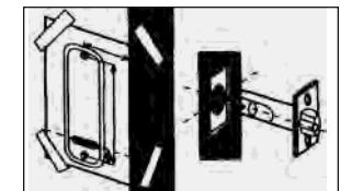
- E-7 Hold the outside and inside units on the door with the spindle in the proper position.
- E-8 Finger-tighten the (2) mounting screws, assuring the lock is vertical and sitting flush against the door.
E-9 Before final tightening, make sure the code works and all features on the unit work as intended.
Note : Do not close the door until the lock has been tested and you are confident it works properly.
E-10 Tighten the mounting screws firmly, being careful not to over tighten the screws, as this may cause the lock to function poorly or not at all.
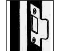
F. INSTALLING THE STRIKE PLATE
- F-1 Push the door nearly shut to locate the center line of the latch bolt. Mark the center line on the door frame.
- F-2 Using the strike, align the center of the strike opening with the center just marked.
Make sure to account for any weather stripping or door stop if necessary.
- F-3 Carefully trace the outside profile of the strike. Also trace the latch hole in the strike.
- F-4 Using a chisel, carefully remove approximately 1 ⁄16" (1 mm) deep worth of material from the traced area (already prepped on most metal doors). The latch face plate should sit flush with the edge of the door.
- F-5 Drill or cut a recess in the door frame for the latch bolt in the center of the strike latch hole, traced earlier.
- F-6 Place the strike into the newly chiseled area, making sure it sits flush and there are no obstructions in the latch hole of the strike (remove any obstructions or debris).
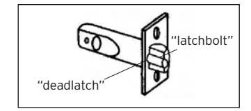
NOTE : The dead-latch must not fall into the latch hole. The dead-latch protects against manipulation of the latch bolt. If the dead-latch is able to fall into the latch hole, remove the strike and reposition it so this condition does not happen.
F-7 Install the strike plate with 2 screws provided.
G. CHANGING THE CODE
- G-1 Remove the lock from the door.
- G-2 Remove the 4 retaining (red) screws from the back of the outside unit assembly. Take extra care to keep the outside unit assembly on a flat surface when you are removing the cover plate because there are many small components inside. "deadlatch"
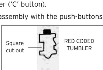
- G-3 You will now see that there are 5 red color coded tumblers and 8 blue colored un-coded tumblers, plus 1 clear tumbler ('C' button).
G-4 To change your code, hold the outside unit assembly with the push-buttons facing down. Press the "C" button and
If the "C" is not held in while changing the code, the lock can be damaged.
hold it.
G-5 Using the tweezers supplied (or small needle nose pliers), you can easily remove one or more of the coded and un-coded tumblers.
Note : The red tumblers represent coded digits and the blue tumblers represent non-coded digits.
Note : NEVER remove the 'C' tumbler.
G-6 Please note the different shapes of the tumblers before reinserting them into the lock body. There is a difference in shape between the coded and un-coded tumblers as illustrated. When refitting
Square cut out push button Square cut out
the tumblers into the lock body, they must be fitted facing the correct way as show in the illustration.
Note : All square cutouts must face outwards. The bump on the tumbler (either color) must fall into the machined slot.
G-7 After you have refitted the tumblers and made a note of the new code, replace the metal cover plate with the 4 screws.
Note : With the spare tumblers provided, you can either increase the number of digits in your code to 6-7, or reduce to 3-4.
Square cut out
BLUE UNCODED TUMBLER
"latchbolt"
2 3/8" (60 mm) Backset ONLY. From outside, f ←Outline of 2 <sup>3</sup>/4" (70 mm) 2 <sup>3</sup>/8" (60 mm) LD470 Series Outline of Lock Housing TEMPLATE TOP 3%"(10 mm) Hole 2 <sup>3</sup>/<sub>4</sub>" (70 mm) 2 <sup>3</sup>/8" (60 mm) outside, fold along the left edge of the door
2 3/4" (70 mm) Backset ONLY. From outside, f
outside, fold along the left edge of the door

NO POSTAGE NECESSARY IF MAILED IN THE UNITED STATES

POSTAGE WILL BE PAID BY ADDRESSEE
KABA ACCESS CONTROL 2941 INDIANA AVENUE WINSTON-SALEM, NC 27199-3770

REGISTRATIONCARD
❏ Thislockwillbeusedinwhattypeof
Commercial
Building
❏
Industrial/
Manufacturing
❏
Airport
facility?
registeronlineat cardandreturnittoKabaAccessControl,or serveyouinthefuture,pleasefilloutthisprotectyourinvestmentandtoenableustoThankyouforpurchasingourproduct.Inorderto www.kabaaccess.com
|
Ac
ce ss Co nt ro l loc ks |
or
e in fo rm at io n on Ka ba |
yo
u wo ul d lik e m |
❏
Ch ec k he re if |
|||
|---|---|---|---|---|---|---|
|
❏
Ot he r |
❏
Ma int en an ce |
❏
Lo ck sm ith |
l
Nu m be r |
Mo
de |
||
|
loc
k? |
W
ho in st al led yo ur |
rc
ha se |
of
Pu |
|||
|
ale
r Pu rc ha se d Fr om |
of
De |
|||||
|
th
is loc k? |
as
on fo r bu yi ng |
W
ha t wa s yo ur re |
||||
|
❏
Ot he r (p lea se sp ec ify ) |
ce
❏ Tr ai ni ng Cl as s |
❏
Ma int en an |
❏
Lo ck sm ith |
|||
|
Lo
❏ ck s? An ot he r Us e |
Us
ce e ss Co ❏ nt Int ro l er Pu ne sh t / bu W tt eb on |
ab
❏ ou t Pr Ka ev io ba us Ac |
❏
Ho w Ad di ve d rti yo se u m lea en rn t |
Co
un tr y |
ZI
P (P os ta l Co de ) |
|
|
th
an Ka ba |
yle
ss Lo ck ot he r |
❏
Re pla cin g a Ke |
||||
|
ce
ss Co nt ro l |
ba
Ele ct ro nic Ac |
❏
Re pla cin g a Ka |
||||
|
Pu
sh bu tto n Lo ck |
ba
Me ch an ica l |
❏
Re pla cin g a Ka |
||||
|
loc
k |
nv
en tio na l ke ye d |
❏
Re pla cin g a co |
||||
| n |
❏
Th is Ne loc w k Ins is: ta lla tio |
|||||
|
Co
m m on Do or , Ex er cis e Ro om ) |
th
is loc k? (e .g. Fr on t Do or , |
g
se cu re d wi th |
W
ha t ar ea is be in |
om |
on
lin e at w w w. ka ba ac ce ss .c |
|
|
he
r (p lea se sp ec ify ) |
hc
ar e ❏ Ot |
❏
Ho sp ita l/ He alt |
th
nt is ro re l, gi or st ra tio n |
re
in tu th rn e fu it tu to re Ka , pl ba ea Ac se ce fil ss l ou Co t |
an
yo d u |
|
|
❏
Sc ho ol /E du ca tio na l |
ve
rn m en t/ Mi lita ry |
sit
y ❏ Go |
❏
Co lle ge /U niv er |
le
us to be tt er |
ur
in ve st m en t an d to en ab |
yo |
State City
Lock
Dateof
Nameof
Email Phone
Address Company Position Name
H. USING THE PASSAGE FUNCTION
- H-1 Enter the user access code, followed by the "F" button.
- H-2 Rotate the outside lever repeatedly. The latch should retract each time. You are now in the passage mode.
NOTE : To disable the passage function, depress the "F" button, followed by the "C" button. The unit should now be locked.
I. REMOVING THE PASSAGE FUNCTION
If the passage function is not needed it can be easily removed.
- I-1 Remove the 4 red screws located on the back of the outside unit assembly. Pull the tumbler cover plate off (along with the springs) and set aside.
- I-2 Depress the "C" button and hold depressed.
- I-3 With the "C" still depressed, use the tweezers provided and remove the "F" tumbler.
- I-4 This tumbler hole can be left empty or replaced with a blue (uncoded) tumbler.
- I-5 Reinstall the tumbler cover plate and springs, using the 4 red screws removed earlier.
J. TROUBLE SHOOTING
Installation Issues:
- ? The latch cannot be withdrawn when entering the code
- ➔ The lock has been fitted to a left-hand hung door
- - All locks were set to fit right-hand hung doors. The lock needs to be removed from the door and reversed. Refer to instructions.
- ? Both the inside and outside lever retract when turned towards the door frame.
- ➔ The spindle is in position at the wrong angle.
- - Remove the lock from the door, and reposition the spindles as shown in the instructions.
- ? The lever will not turn after entering a new code.
- ➔ One or more of the code tumblers are turned the wrong way
- - Re-read the code change instructions and check that the red tumblers are all facing with the square notches facing outward.
- ? The latch bolt does not move smoothly in or out.
- ➔ The lock is not installed correctly.
- - Check that the lock is square on the door and positioned accurately over the latch. Check that the latch is positioned horizontally and parallel to the door surface. Check the spindle length. It may be trapped between the front and back plate if the spindle is too long.
- ? The outside lever turns after entering a correct code, but does not retract the latch.
- ➔ The spindle is too short for the door thickness.
- - If the spindle is too short, then it will not engage with both the outside lever and the inside lever at the same time. It may also slip out of one side after some use.
Post-Installation Issues:
- ? The outside lever turns freely without retracting the bolt.
- ➔ The lever has been forcibly turned.
- -Return the lock. Someone may have tried to force the lever to gain entry.
- ? The inside lever handle does not return to the horizontal after operating.
- ➔ The lever return spring is broken.
- -Call the help line for a replacement
- ? The latch does not engage. The door remains unlocked after use.
- ➔ The latch is not entering the strike.
- - Your door or frame may have warped since the lock was installed. Check that the latch bolt is lined up with the strike aperture. Realign the position of the strike as necessary. Make sure the deadlatch does not enter the latch hole of the strike.
KABA SIMPLEX® LIMITED WARRANTY
Kaba Access Control warrants this product to be free from defects in material and workmanship under normal use and service for a period of one (1) year. Kaba Access Control will repair or replace, at our discretion, locks found by Kaba Access Control analysis to be defective during this period. Our only liability, whether in tort or in contract, under this warranty is to repair or replace products that are returned to Kaba Access Control within the one (1) year warranty period.
This warranty is in lieu of and not in addition to any other warranty or condition, express or implied, including without limitation merchantability, fitness for purpose or absence of latent defects.
ATTENTION: This warranty does not cover problems arising out of improper installation, neglect or misuse. All warranties implied or written will be null and void if the lock is not installed properly and /or if any supplied component part is substituted with a foreign part. If the lock is used with a wall bumper, the warranty is null and void. If a doorstop is required, we recommend the use of a floor secured stop.
The environment and conditions of use determine the life of finishes on Kaba Access Control products. Finishes on Kaba Access Control products are subject to change due to wear and environmental corrosion. Kaba Access Control cannot be held responsible for the deterioration of finishes.
Authorization to Return Goods
Returned merchandise will not be accepted without prior approval. Approvals and Returned Goods Authorization Numbers (RGA Numbers) are available through our Customer Service department in Winston-Salem, NC (800) 849- 8324. The serial number of a lock is required to obtain this RGA Number . The issuance of an RGA does not imply that a credit or replacement will be issued.
The RGA number must be included on the address label when material is returned to the factory. All component parts including latches and strikes (even if not inoperative) must be included in the package with return. All merchandise must be returned prepaid and properly packaged to the address indicated.

Kaba Access Control 2941 Indiana Avenue Winston-Salem, NC 27105 USA Tel: (800) 849-8324 (336) 725-1331 Fax: (800) 346-9640 (336) 725-3269