Simplex 7106 Installation Instructions
Open the original PDF document
View PDF
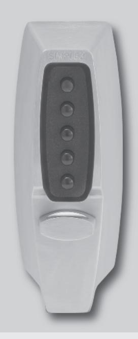

SIMPLEX® 7106 Series Pushbutton Lock Installation Instructions
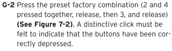
Important : Please keep these instructions. The combination of this lock has been factory preset: 2 and 4 pressed together, then 3.
WARNING
For your own safety, you must change the combination at the time of installation.
PLEASE READ AND FOLLOW ALL DIRECTIONS CAREFULLY
Since every installation is unique, carefully check windows, frame, door, etc. to ensure that the recommended procedures will not cause damage. KABA is not responsible for any damage caused by installation.
Tools Required
- 1 ⁄8" (3 mm) Drill Bit
- 1 ⁄4" (6 mm) Drill Bit
- 1" (25 mm) Wood Chisel
- 3 ⁄4" (19 mm) Hole Saw
- 1 3 ⁄8" (35 mm) Hole Saw
- Phillips-head Screwdriver
- 2 Pairs of Pliers
- Hacksaw
- Hammer
- Center Punch
- Drill (variable speed recommended)
Caution : Wear safety glasses when preparing door.
Table of Contents
| Checklist4 | ||
|---|---|---|
|
Determining
the Hand of Your Door4 |
||
| A. |
Determining
the Lock Location5 |
|
| B. |
Marking
the Door5 |
|
| C. |
Drilling
Holes in the Door6 |
|
| D. |
Adjusting
the Lock6 |
|
| E. |
Installing
the Lock7 |
|
| F. |
Reversing
the Latch8 |
|
| G. |
Checking
the Lock's Operation9 |
|
| H. |
Verifying
the Combination Change Assembly12 |
|
| I. |
Installing
the Strike12 |
|
| J. |
Changing
the Combination13 |
|
| K. |
Instructions
for Resetting an Unknown Combination15 |
|
| L. | Troubleshooting16 | |
|
Templates
(Center of Manual) |

For technical assistance please call 1.800.849.TECH (8324) or 1.336.725.1331
CHECKLIST
Use this checklist to make sure that everything has been included. o 4
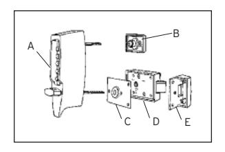
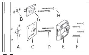
- q A – Front lock
- q B – Inside combination change assembly
- q C – Reinforcing plate
- q D – Inside rim deadlocking latch
- q E – Strike box
-
q
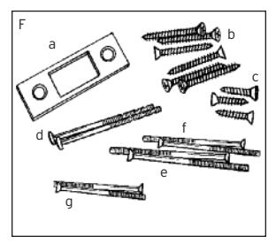
F –
Screw pack
- a. Flat strike plate
- b. Six 1 3 ⁄4" (44 mm) screws 4 for inside rim deadlocking latch 2 for strike box
- c. Three 1" (25 mm) flat head strike screws
- d. Two 2 3 ⁄4" (70 mm) round head break away reinforcing plate thru bolts
- e. Two 3" (76 mm) flat head inside combination change assembly thru bolts
- f. Two 2 3 ⁄8" (60 mm) flat head inside combination change assembly thru bolts
- g. Two 2" (51 mm) flat head inside combination change assembly thru bolts
- q Template (in center of booklet)

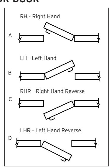
Many of the installation instructions refer to the handing of your door. The hand of the door is determined with the door in the closed position, from the exterior or pushbutton side of the door.
- A) Right Hand Door. Door opens inward (push). Hinged on the right side.
- B) Left Hand Door. Door opens inward (push). Hinged on the left side.
- C) Right Hand Reverse Door. Door opens outward (pull). Hinged on the right side.
- D) Left Hand Reverse Door. Door opens outward (pull). Hinged on the left side.
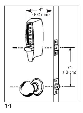
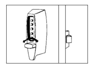
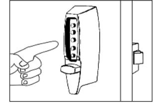
A. DETERMINING THE LOCK LOCATION
Install the lock with exterior thumbturn hole at least 7" (18 cm) above your primary lockset so it is comfortable to operate and not in the way when you turn the door knob (See Figure 1-1) . Minimum stile width recommended: 4" (102 mm).
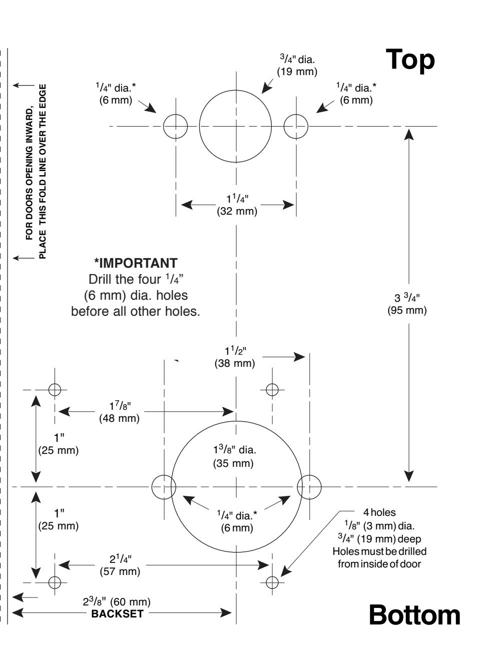
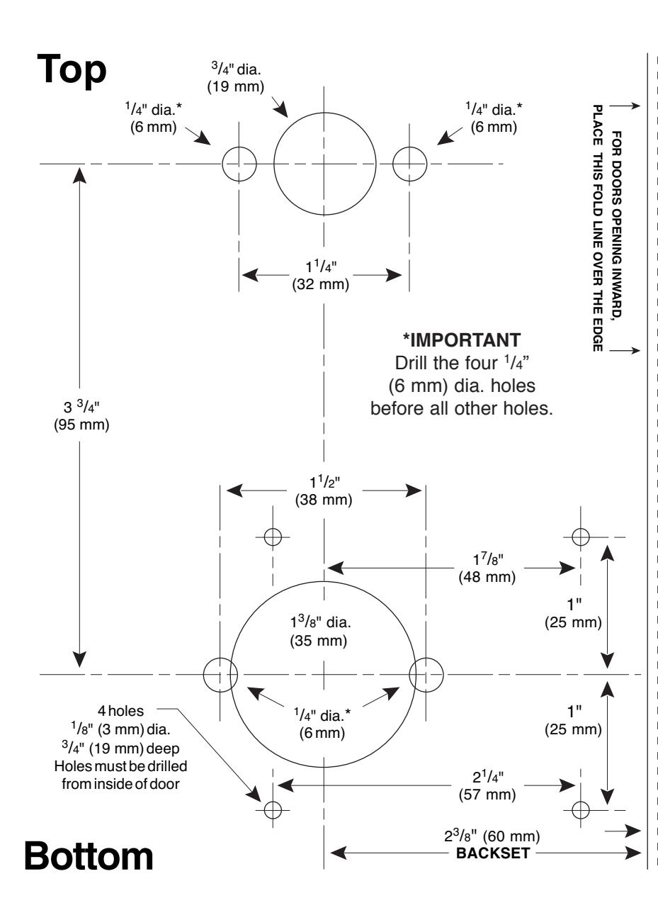
B. MARKING THE DOOR
B-1 Doors Opening Inward
- a. Fold the template ( A ) on the solid line ( B ).
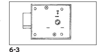
- b. Tape the template securely to the inside of the door so that the fold is properly aligned with the edge of the door (See Figure 2-1).
- c. Use a center punch to mark the ten drilling points indicated on the template.
- d. Remove the template.
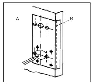
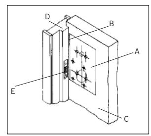
B-2 Doors Opening Outward
- a. Fold the template ( A ) on the dashed line ( B ).
- b. Tape the template securely to the inside of the door ( C ) so that the dashed line is aligned with the face of the door jamb ( D ) (See Figure 2-2).
- c. Use a center punch to mark the ten drilling points indicated on the template.
- d. Remove the template.
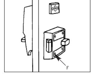
Note: You may install the strike ( E ) at this point. See Section I - Installing the Strike.
2-1
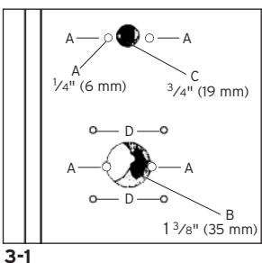
C. DRILLING HOLES IN THE DOOR
CAUTION: Positioning and drilling must be done straight to ensure trouble free operation of the model 7106 lockset. Improper drilling may result in excessive force being exerted on the lock which may result in the premature wearing of its mechanical parts.
Perform Step 1 first or it will be impossible to drill the four " (6 mm) holes.
- C-1 Use a ¼" (6 mm) drill bit to drill the four holes for the thru-bolts (See A in Figure 3-1). To prevent splintering the door or breaking the drill bit, begin drilling at a slow speed and increase the speed gradually until the tip of the drill bit emerges from the other side of the door. Repeat this procedure from the opposite side of the door.
- C-2 Use a hole saw with a pilot bit to make the 1 3/8" (35 mm) hole ( B ). Apply pressure evenly until the circular blade cuts the first side of the door and the tip of the
pilot bit emerges through the other side, then stop. Drill from the other side until the 1 3/8"
(35 mm) hole ( B ) is completed.
C-3 Repeat Step C-2 for the <sup>3</sup>/<sub>4</sub>" (19 mm) hole (See C in Figure 3-1).
C-4 Drill the four 1/8" (3 mm) holes only 3/4" (19 mm) deep (See D in Figure 3-1).
D. ADJUSTING THE LOCK
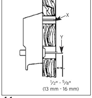
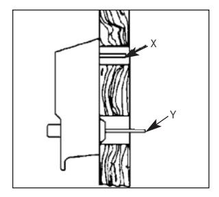
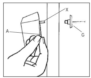
The lock has been pre-assembled to accommodate doors up to " (57 mm) thick. If your door is " to 2" (35 mm to 51 mm) thick, you must shorten both tailpieces X and Y (See Figure 4-1) and shorten the ( A ) Two thru-bolts used to secure the ( B ) combination change assembly.
-
D-1
Shorten the combination change tailpiece
X
according to your door thickness. Tailpiece
X
has been pre-marked for various door thicknesses for accuracy and convenience.
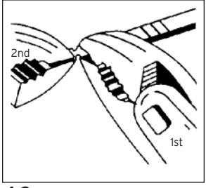
- a) After determining the break line, hold the tailpiece firmly with a pair of pliers on the lock side of the tailpiece, just beside the desired break line.
- b) With a second pair of pliers, grip the tailpiece at the other side of the line and bend it up and down until it breaks ( See Figure 4-2 ).
-
D-2
While holding the lockset firmly against the outside of the door,
(See Figure 4-1)
mark tailpiece
Y
at the point where it extends
1
⁄2" -
5
⁄8" beyond the interior surface of the door.
- a) After determining the break line, hold the tailpiece firmly with a pair of pliers on the lock side of the tailpiece, just beside the desired break line.
- b) With a second pair of pliers, grip the tailpiece at the other side of the line and bend it up and down until it breaks (See Figure 4-2) .
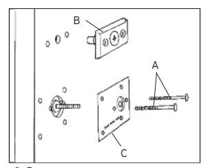
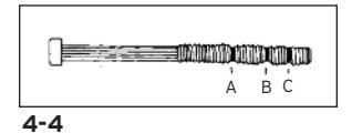
- D-3 Shorten each of the two reinforcing plate thrubolts ( A ) (See Figure 4-3) by gripping at the threaded end with pliers and sawing through at the correct length (See Figure 4-4) with a fine-tooth hacksaw.
4-3
Note : Be careful not to damage the threads when shortening the thru-bolts.
- For 1 3 ⁄8" (35 mm) thickness doors, shorten thru-bolt at A .
- For 1 3 ⁄4" (45 mm) thickness doors, shorten thru-bolt at B .
- For 2" (51 mm) thickness doors, shorten thru-bolt at C .
- For 2 1 ⁄4" (57 mm) thickness doors, leave thru-bolt as is.
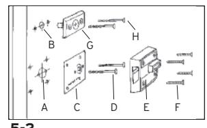
- D-4 To secure the ( B ) combination change assembly (See "G" Figure 5-2) , utilize two 2" (51 mm) bolts ( H ) for door thickness 1 3 ⁄8" (35 mm) to 1 1 ⁄2" (38 mm). For door thickness 1 1 ⁄2" (38 mm) - 2" (51 mm) utilize two 2 3 ⁄8" (60 mm) bolts ( H ). For door thickness 2" (51 mm) - 2 1 ⁄4" (57 mm), utilize two 3" (76 mm) thru-bolts ( H ).
E. INSTALLING THE LOCK
The model 7106 lock is packaged for an inward opening door. For an outward opening door, the latch must be reversed (See Section F) .
Figures 5-1 (outside of door) and 5-2 (inside of door) show how the lock is installed and identify each component by letter. Refer to these figures as you follow the steps below.
E-1 Insert tailpiece ( Y ) into the 1 3 ⁄8" (35 mm) cutout ( A ) and the combination change tailpiece ( X ) into the 3 ⁄4" (19 mm) hole ( B ) (See Figure 5-1 and 5-2).
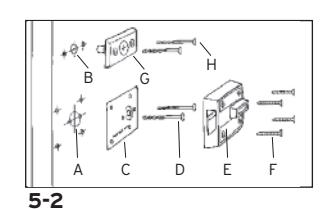
- E-2 While holding the lock firmly against the outside of the door, use two round head thrubolts ( D ) to secure the inside reinforcing plate ( C ). Finger tighten only.
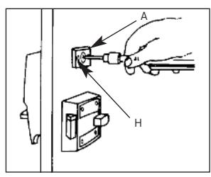
- E-3 Use a thin object A (screwdriver) to align tailpiece ( X ) with the horizontal slot of the combination change assembly ( G ) (See Figure 5-3) . Attach the combination change assembly ( G ) with two flat head thru-bolts ( H ). Finger tighten only (See Figure 5-2).
- E-4 Securely tighten the two thru-bolts ( D ) to reinforcing plate ( C ) (See Figure 5-2).
- E-5 Position the cam on the inside rim deadlocking (See Figure 5-4) . Turn cam to the right (clockwise) manually until it stops.
- E-6 Mount the inside rim deadlocking latch ( E ) so that tailpiece Y is engaged in the vertical position. Secure evenly with four screws ( F ). (See Figure 5-2).
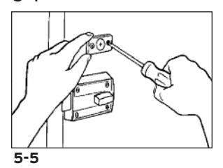
- E-7 Lightly push the combination change assembly down and secure screws evenly (See Figure 5-5).

The model 7106 lock is packaged for an inward opening door. For an outward opening door, the latch must be reversed.
- F-1 With the latch extended ( A ), remove the two backplate screws from the underside of the inside rim deadlocking latch. Remove the backplate using a small flat blade screwdriver.
- F-2 Carefully remove the latch spring ( B ) and auxiliary latch spring ( C ) with a small flat blade screwdriver.
- F-3 Press the latch and auxiliary latch ( D ) into the case to the stop position (See Figure 6-1) .
5-2
5-3
5-4
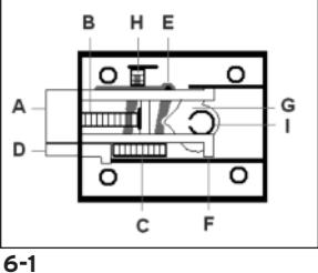
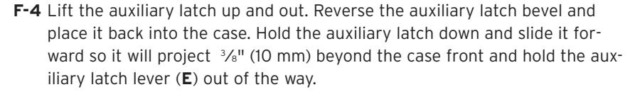
F-5 While holding the auxiliary latch as instructed in step 4, place the latch in the case with the bevel in the same direction as the auxiliary latch. Make sure the latch legs ( F ) are caught on the ears of the turn knob lever ( G ) (See Figure 6-2) .
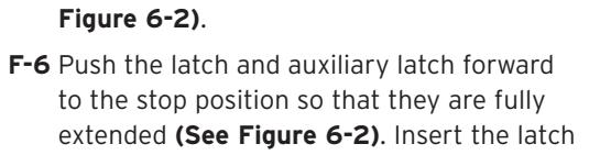
- spring ( H ) (large opening of spring) towards back of latch and the (small opening of spring) against the spring seat. Insert one end of the auxiliary latch spring into the back of the auxiliary latch and place the other end of the spring against the spring seat.
- F-7 When the springs are installed, the auxiliary latch lever (shaded area in Figure 6-2 ) should be in the position shown in Figure 6-2 .
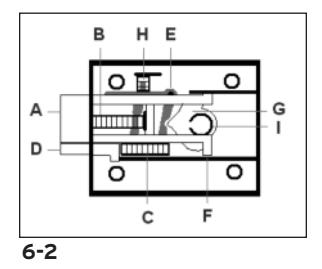
- F-8 If the cam ( I ) falls out, replace it in the thumbturn hole with the circular opening facing up. Place the backplate onto the case with the letters facing up towards you, and fasten with two screws removed in step 1 (See Figure 6-3) . Check the lock for freedom of movement by depressing the
latch and auxiliary latch into the lock case, then make sure that the latch and auxiliary latch return back to their original fully extended position (See Figure 6-3) .
To Install the Lock, See Section E
G. CHECKING THE LOCK'S OPERATION
Important: The following steps must be performed while the door is open.
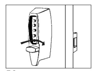
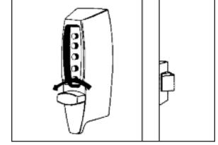
G-1 Turn the outside thumbturn to the left (counterclockwise) until it stops, then release it (See Figure 7-1) .
7-1
KABA SIMPLEX® LIMITED WARRANTY
Kaba Access Control warrants this product to be free from defects in material and workmanship under normal use and service for a period of one (1) year. Kaba Access Control will repair or replace, at our discretion, locks found by Kaba Access Control analysis to be defective during this period. Our only liability, whether in tort or in contract, under this warranty is to repair or replace products that are returned to Kaba Access Control within the one (1) year warranty period.
This warranty is in lieu of and not in addition to any other warranty or condition, express or implied, including without limitation merchantability, fitness for purpose or absence of latent defects.
ATTENTION: This warranty does not cover problems arising out of improper installation, neglect or misuse. All warranties implied or written will be null and void if the lock is not installed properly and/or if any supplied component part is substituted with a foreign part. If the lock is used with a wall bumper, the warranty is null and void. If a doorstop is required, we recommend the use of a floor secured stop.
The environment and conditions of use determine the life of finishes on Kaba Access Control products. Finishes on Kaba Access Control products are subject to change due to wear and environmental corrosion. Kaba Access Control cannot be held responsible for the deterioration of finishes.
Authorization to Return Goods
Returned merchandise will not be accepted without prior approval. Approvals and Returned Goods Authorization Numbers (RGA Numbers) are available through our Customer Service department in Winston-Salem, NC 1.800.849.8324. The serial number of a lock is required to obtain this RGA Number . The issuance of an RGA does not imply that a credit or replacement will be issued.
The RGA number must be included on the address label when material is returned to the factory. All component parts including latches and strikes (even if not inoperative) must be included in the package with return. All merchandise must be returned prepaid and properly packaged to the address indicated.
REFERENCE ONLY, NOT TO SCALE DO NOT USE AS A DRILLING TEMPLATE CALL 800-849-8324
REFERENCE ONLY, NOT TO SCALE DO NOT USE AS A DRILLING TEMPLATE CALL 800-849-8324
NOTE: Lock will accomodate doors 13/8" (35 mm) to 21/4" (57 mm) thick. Suitable reinforcement shall be provided by the hollow metal door manufacturer to prevent collapsing of door. When door silencers are to be installed, proper allowances must be made for strike location.
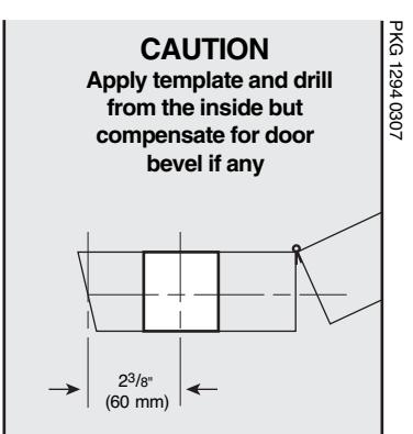
7106 TEMPLATE RIGHT HAND DOOR MARK ACCURATELY BORE STRAIGHT Place this template on the INTERIOR SIDE OF THE DOOR
NTERIOR SIDE OF THE DOOI using the correct fold line for door edge for door opening inward or outward.
<sup>3</sup>/<sub>32</sub>" (2 mm)
CAUTION
PKG1294 0307
Apply template and drill from the inside but compensate for door bevel if any
NOTE: Lock will accomodate doors 13/s" (35 mm) to 21/4" (57 mm) thick. Suitable reinforcement shall be provided by the hollow metal door manufacturer to prevent collapsing of door. When door silencers are to be installed, proper allowances must be made for strike location.
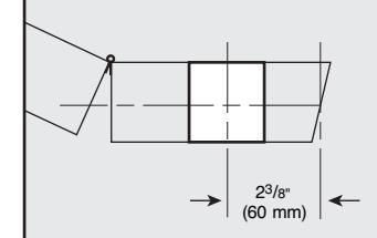
7106
LEFT HAND DOOR
MARK ACCURATELY BORE STRAIGHT
Place this template on the INTERIOR SIDE OF THE DOOR using the correct fold line for door edge for door opening inward or outward.
<sup>3</sup>/<sub>32</sub>" (2 mm)

NO POSTAGE NECESSARY IF MAILED IN THE

UNITED STATES
BUSINESS REPLY MAIL FIRST-CLASS MAIL PERMIT NO. 1563 WINSTON-SALEM, NC
POSTAGE WILL BE PAID BY ADDRESSEE
KABA ACCESS CONTROL 2941 INDIANA AVENUE WINSTON-SALEM, NC 27199-3770

|
Ac
ce ss Co nt ro l loc ks |
in
fo rm at io n on Ka ba |
ul
d lik e m or e |
Ch
ec k he re if wo |
o | ||
|---|---|---|---|---|---|---|
|
o
Ot he r |
Ma
int en an ce |
o |
Lo
ck sm ith |
o |
m
be r |
Lo
ck Mo de l Nu |
|
ho
in st al led yo ur loc k? |
W | se |
Da
te of Pu rc ha |
|||
|
r
Pu rc ha se d Fr om |
Na
m e of De ale |
|||||
|
loc
k? |
r
bu yi ng th is |
ha
t wa s yo ur re as on fo |
W |
Em
ai l |
||
|
o
Ot he r (p lea se sp ec ify ) |
o
Tr ai ni ng Cl as s |
Ma
int en an ce |
Lo
ck sm ith o |
o |
Ph
on e |
|
|
Lo
o ck s? An ot he r Us e |
Co
o nt ro Int l er Pu ne sh t/W bu eb tt on |
Pr
Ka ev io ba us Ac Us ce e ss |
w
Ad di ve d rti yo se u m lea en rn t ab o ou t |
Co
un tr y o Ho |
ZI
P (P os ta l Co de ) |
St
at e |
|
Ka
ba |
ck
ot he r th an |
Re
pla cin g a Ke yle ss Lo |
o |
Ci
ty |
||
|
Co
nt ro l |
ct
ro nic Ac ce ss |
Re
pla cin g a Ka ba Ele |
o |
Ad
dr es s |
||
|
tto
n Lo ck |
ch
an ica l Pu sh bu |
Re
pla cin g a Ka ba Me |
o |
Co
m pa ny |
||
|
na
l ke ye d loc k |
Re
pla cin g a co nv en tio |
o | ||||
|
Ne
w Ins ta lla tio n |
o |
Po
sit io n |
||||
|
is
loc k is: |
Th |
Na
m e |
||||
|
,
Co m m on Do or , Ex er cis e Ro om ) |
loc
k? (e .g. Fr on t Do or |
re
d wi th th is |
ha
t ar ea is be in g se cu |
W | ||
|
nt
om ro l, or |
e
rn at it w to w w. Ka ka ba ba Ac ac ce ce ss ss Co .c |
ca
re gi rd st an er d on re lin tu |
||||
|
lea
se sp ec ify ) |
o
Ot he r (p |
Ho
sp ita l/ He alt hc ar e |
th
is re gi st ra tio n o |
th
e fu tu re , pl ea se fil l ou t |
se
rv e yo u in |
|
|
o
Sc ho ol /E du ca tio na l |
m
en t/ Mi lita ry |
o
Go ve rn |
Co
lle ge /U niv er sit y |
le
us to be tt er o |
in
ve st m en t an d to en ab |
pr
ot ec t yo ur |
|
o
Ai rp or t |
al/
Ma nu fa ct ur ing |
o
Ind us tri |
Co
m m er cia l Bu ild ing |
t.
In or de r to o |
r
pu rc ha si ng ou r pr od uc |
Th
an k yo u fo |
|
fa
ci lit y? |
wh
at ty pe of |
is
loc k wi ll be us ed in |
Th |
A
T IO N C A R D |
R
E G IS T R |
here if you would like more
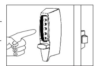
G-3 Turn the outside thumbturn to the right (clockwise) until it stops (See Figure 7-3) ; the latch should retract fully. If the latch does not retract, turn the thumbturn to the left counterclockwise until it stops, release, and repeat Step G-2.
Note: From the outside, the only way to retract the latch is to turn the thumbturn clockwise.
- G-4 Release the outside thumbturn. The latch should return to its completely extended position.
- G-5 Turn the inside thumbturn to the left (counterclockwise) until it stops; the latch will retract. Release it and the latch will return to its completely extended position (See Figure 7-4) .
Note: The inside thumbturn may be turned to the right (clockwise) to keep the latch retracted. Turn the thumbturn to the left to bring the latch back to its normal extended position.

and 7-5) and remove the latch. Loosen the two thru-bolts ( D ) on the reinforcing plate (See Figure 7-5) . Move the plate up or down, tighten the thru-bolts ( D ), and remount the latch with the four screws ( F ). Check the latch's retraction again and repeat this operation as needed, until the latch completely retracts.
If the latch will not extend and retract freely after performing the above operation, loosen the two thru-bolts ( H ) of the combination change assembly ( G ) (See Figure 7-5) , move the lock up or down, tighten the thru-bolts ( H ), and try to retract the latch again.
7-3
7-4
7-5
H. VERIFYING THE COMBINATION CHANGE ASSEMBLY
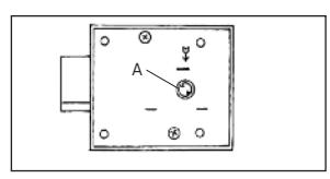
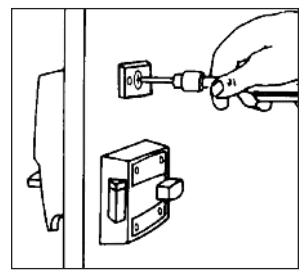
- H-1 Insert the tip of a Phillips-head screwdriver into the central piece of the combination change assembly (See Figure 8-1) .
- H-2 Lightly rotate the screwdriver to the right (clockwise) until it stops. DO NOT FORCE .
- H-3 Remove the screwdriver; the central piece should automatically return to its initial position.
- H-4 If the central piece jams and does not return to its initial position, loosen the two thrubolts ( H ) (See Figure 8-1) and push the combination change assembly ( A ) upward. Tighten the thru-bolts, and repeat Steps H-1 to H-3.
8-1
I. INSTALLING THE STRIKE
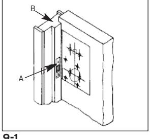
I-1 Outward opening door - mount flat strike
- a. Place the strike ( A ) on the door jamb ( B ) in line with the center line of latch (See Figure 9-1) .
- b. Trace the outline of the strike on the jamb. Remove the strike.
- c. Chisel out the jamb so that the strike will be flush with the surface of the jamb.
- d. Place the strike back into the cutout and trace the latch hole on the jamb.
9-1
e. Chisel this out to clear the 5 ⁄8" (16 mm) long extended latch. The latch must enter the strike freely.
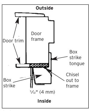
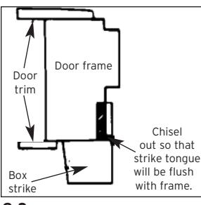
I-2 Inward opening door - mount box strike
- a. Place the strike on the door trim in line with the center line of latch.
- b. Trace the outline of the strike onto the door trim (See Figure 9-2) . Add 5 ⁄32" (4 mm) to the edge of the tracing opposite the lock to allow for recessing of the strike tongue.
- c. Chisel out the traced (shaded area), down to the door frame (See Figure 9-2) .
9-2
- d. Place the strike back into this cutout and trace the outline of the strike tongue (See Figure 9-3) .
- e. Chisel out the frame so that the strike tongue will be flush (approximately 5 ⁄32").
- f. Place the strike back into the cutout and check that the large segment of the latch enters the strike freely.
- g. Secure the strike in the end with two 1 3 ⁄4" (44 mm) screws and on the flat area with three 1" (25 mm) screws provided.
9-3
J. CHANGING THE COMBINATION
Important: The following steps must be performed while the DOOR IS OPEN .
The factory pre-set combination is 2 and 4 pressed simultaneously, then 3.
Read the instructions through once before attempting to change the combination.
- J-1 Turn the outside thumbturn to the left (counterclockwise) until it stops (See Figure 10-1) then return it clockwise slowly to the horizontal position and release.
- J-2 Enter the current combination (See Figure 10-2) .
- J-3 Insert a Phillips-head screwdriver into the central piece of the combination change assembly (See Figure 10-3) . Gently rotate the screwdriver to the right (clockwise) until it stops. A slight click should be felt. DO NOT FORCE .
- J-4 Remove the screwdriver from the combination change assembly.
Important: When removing the screwdriver, the central piece must return to its initial position, if not, set it back to its original position using the screwdriver (See Figure 10-3) . If the central piece of the combination change assembly does not return to its original position, the combination will be cancelled and the lock will jam.
J-5 Turn the outside thumbturn left (counterclockwise) until it stops (See Figure 10-4) and return it slowly clockwise to the horizontal position and release.
10-1
10-2
10-3
10-4
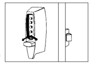
J-6 Select a new combination and write it down (some or all of the buttons may be used for your new combination, pressed individually or simultaneously). Each button may be used only once. We do not recommend the use of a one button combination.
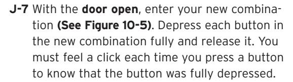
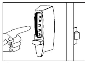
J-8 Turn the outside thumbturn to the right (clockwise) (See Figure 10-6) until it stops; the latch should retract.

10-5
Keep the door open and test the operation of the lock to assure your combination was set correctly.
Operating the lock: Repeat 2-3 times to ensure trouble-free operation with the new combination.
- J-10 Turn the outside thumbturn to the left (counterclockwise) to "clear."
- J-11 Enter the combination. Depress each button in the combination fully and release it. You must feel a click each time you press a button to know that it was fully depressed.
- J-12 Turn the outside thumbturn to the right (clockwise). The latch should retract.
Tests:
- 1) Try to operate the lock without entering a combination. The thumbturn should not turn to the right (clockwise), retracting the latch. If it does turn, retracting the latch, the new combination was not properly set. Set a new combination by following steps J-1 to J-9, omitting step J-2.
- 2) Try to operate the lock by entering a wrong combination. The thumbturn should not turn to the right (clockwise), retracting the latch.
Note: If force resistant clutch is actuated, you will feel a hard click in the outside thumbturn. The lock is designed to do this. The latch still should not retract even though the force resistant clutch was actuated. Keep turning the outside thumbturn and it will reseat in the original position.
K. INSTRUCTIONS FOR RESETTING AN UNKNOWN COMBINATION
Remove the lock from the door. Loosen and remove the 4 screws that hold the backplate on the lock body. Set aside the back plate assuring the tailpieces do not come loose/out ofthe backplate. Remove the drive cam assembly located on the control shaft on the back ofthe chamber. Remove the combination chamber from the lock held by 2 screws.
To remove the 3-sided dust cover marked "Kaba Simplex," place the combination chamber in the position below to the right.
- K-1 Place a small screwdriver on the edge ofthe 3-sided dust cover and push down on the screwdriver (See Figure 11-1) . The cover should pop loose. Once it does, pullthe cover off ofthe combination chamber.
- (3 sided dust cover) 11-1
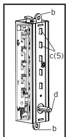
- K-2 Hold the chamber in one hand by the screw tabs ( b ) on each end with the key-stems ( c ) facing you and the control shaft( d ) atthe bottom (See Figure 11-2) .
- K-3 Using pliers or equivalent, rotate the control shaft( d ) counterclockwise and release to clear the chamber (See Figure 11-2) .
- K-4 Look atthe 5 code gears ( e ). If any code gear pockets ( f ) are already atthe shear line (open position), ignore them. They are not used in the combination (See Figure 11-3) .
NOTE : Shear line (open position) references the "L" shaped feet already align with the mating gear pocket(f)
K-5 Find the code gear pocket/s ( e )thatis farthest away from the shear line (open position). Depress that key-stem/s ( c ) and release (See Figure 11-3) . If any digits in the combination were depressed together (atthe same time),then they must also be depressed together to reset the combination.

NOTE: If any ofthe code gear pockets travel pastthe shear line (open position),the key stems have been depressed in the wrong sequence. Start over at K-3.
- K-7 Repeat step K-6 until all code gear pockets ( e ) are atthe shear line (open position).
- K-8 If allthe code gear pockets ( e ) are notlined up atthe shear line (open position), start over at step K-3.
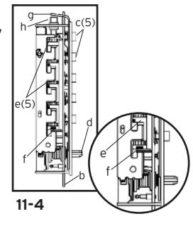
- K-9 Depress the lockout slide ( g ) atthe top ofthe chamber and release. (looks like one end of a spark plug) (See Figure 11-3).
- K-10 Using pliers or equivalent, rotate the control shaft( d ) counterclockwise to clear the chamber and release. The lockout slide ( g ) should pop out(button underneath will stay depressed) (See Figure 11-3) .
11-2
d
f e b
g c(5)
f
11-3
e(5)
- K-11 Depress the key-stem/s (c) that you wantin the new combination, releasing each after itis depressed (See Figure 11-4) .
- K-12 Once allthe digits in the new combination have been depressed, using pliers or equivalent, rotate the control shaft (d) clockwise (See Figure 11-4) . The code change button (h) underneath the lockout slide (g), should pop up (See Figure 11-4) . The new combination is now set.
- K-13 Look atthe code gear pockets (e) . The numbers in the new combination should not be atthe shear line (open position) (See Figure 11-4) . If all look like (f), start over at Step K-3.
Reinstallation : Replace the 3-sided dust cover marked "Kaba Simplex." Make sure the staked joints on both end plates fitthrough the slots on the dust cover. Stake the 2 end plate joints. Replace the combination chamber into the lock using the same 2 screws removed earlier. Slip the drive cam assembly back on the control shaft ofthe chamber assuring itis in the same position as prior to removal. Re-secure the back plate, assuring the tailpieces are seated correctly using the same 4 screws removed earlier. Reinstallthe lock back on the door.
Testing : Enter the combination set during the reset process. Turn the outside thumbturn to the right(clockwise). The latch should retract. Ifthe latch does not retract,turn the outside thumbturn left(counterclockwise) and release,then enter the code again.
L. TROUBLESHOOTING
- ? Lock fails to open when combination is entered and outside thumbturn is rotated clockwise.
- ' Buttons were notfully depressed when the combination was entered.
- ' Lock not cleared of previous attempts to enter combination.
- F Turn the outside thumbturn to the leftto clear the wrong entry. Enter the combination making sure you feel each button click to know that it was depressed fully. Turn thumbturn clockwise.
- ? Turning outside thumbturn clockwise always retracts latch without depressing any buttons.
- ' Lock is in zero combination.
- F Follow the procedure for setting a new combination (Section J, but omit Step J-2).
- ? Inside thumbturn only retracts bolt partially or not at all, in either clockwise or counterclockwise direction.
- ' Bolt was not properly installed.
- F Remove and re-installthe bolt. Review and follow instructions in Section E.
- ? After setting a new combination,the lock works one time only,then fails to open.
- ' Buttons ofintended combinationwere notfully depressedwhen changing combination.
- F This is a lost combination situation. Review and follow instructions in Section K.
| Notes | ||
|---|---|---|

Kaba Access Control
2941 Indiana Avenue Winston-Salem, NC 27105 USA Tel: 800.849.8324 or 336.725.1331 Fax: 800.346.9640 or 336.725.3269