Simplex 5000 Series Exit Trim Installation Instructions
Open the original PDF document
View PDF
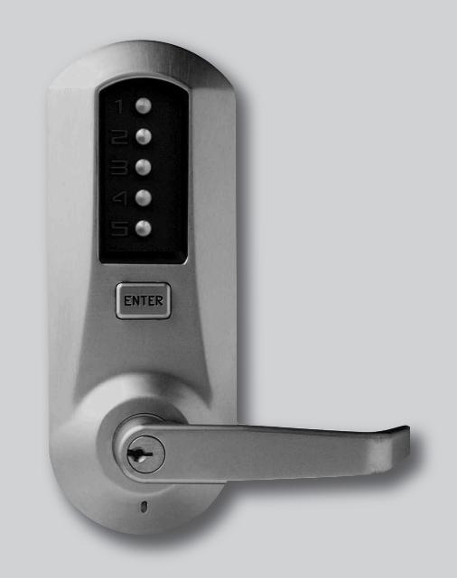


Simplex 5010 Exit Trim
Installation Instructions

Kaba Access Control 2941 Indiana Avenue Winston-Salem, NC 27105 USA Tel: (800) 849-8324 (336) 725-1331 Fax: (800) 346-9640 (336) 725-3269
TABLE OF CONTENTS
| Ass | Assembly Drawing (Simplex 5000 Exit Trim) | ||||||
|---|---|---|---|---|---|---|---|
| Too | Tools Required4 | ||||||
| A. | Door Preparation - Exit Device5 | ||||||
| В. | Door Preparation - Simplex 5000 Exit Trim6 | ||||||
| С. | Install Exit Device6 | ||||||
| D. | Door Thickness6 | ||||||
| E. | Assemble Outside Unit to Universal Mounting Plate7 | ||||||
| F. | Lock Handing | ||||||
| G. | Changing Key-in-Lever (KIL) Cylinder | ||||||
| Н. | Installing / Removing Outside Lever (Key-in-Lever Models) | ||||||
| l. | Installing / Removing Outside Lever | ||||||
| (Interchangeable / Removable Core Models) | |||||||
| J. | Installing Simplex 5000 Exit Trim | ||||||
| K. | Testing Operation of the Lock | ||||||
| L. | Changing Combinations | ||||||
| Μ. | Reset a Lost or Unknown Combination | ||||||
| N. | Troubleshooting | ||||||
Warning
The combination of this lock has been factory preset, 2 & 4 depressed at the same time, then 3 and then ENTER. For your security, the combination must be changed at time of installation.
Warnings and Cautions
Important : Carefully inspect windows, doorframe, door, lights, etc. to ensure that the recommended procedures will not cause damage. Kaba Access Control's warranty does not cover damages caused by installation.
Caution : Wear safety glasses when preparing door.
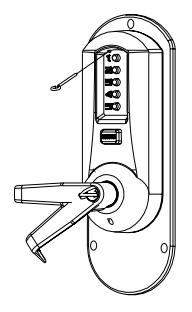
Simplex 5000
The Simplex 5000 Exit Trim lock is adaptable to a wide variety of exit devices on the market today. No tools are required to reverse handing, and the spring loaded tailpiece drive automatically adjusts to door thickness from 1 3/4" to 2 1/8". Door thickness of up to 2 1/4" inches can be accommodated through the addition of a spacer ring. The Simplex 5000 Exit Trim lock accommodates through bolt mounting as used in most fire rated installations as well as surface mounted applications and is retrofitable to existing installations. Before beginning installation, please read and understand all of the following instructions as well as the exit device manufacturer's instructions.
OPERATIONAL NOTE:
The Simplex 5000 Exit Trim lock is in most ways identical to the Simplex 5000 Cylindrical lock with the exception of the operation of the lever and the key override system. When the handing is properly set, rotating the lever upwards will not actuate the latch. The key override system differs in that rotating the key does not actuate the latch as on cylindrical drive models. To use the key override the key must be inserted into the cylinder and rotated counter clockwise till it stops (approximately 90 degrees). Then while holding the key in this position with one hand, use the other hand to rotate the lever downwards to retract the latch. Once the lever has rotated a few degrees, the key may be released.
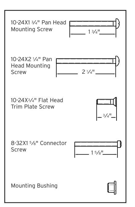
TOOLS REQUIRED
- Safety glasses
- Electric drill (variable speed)
- Awl or center punch
- 2 1 ⁄8" (54 mm) hole saw pilot drill
- 3⁄8" (25 mm) hole saw pilot drill
- Hammer
- Phillips head screwdriver
- Small flat blade screwdriver

For technical assistance please call 1-800-849-TECH (8324) or 336-725-1331
A. DOOR PREPARATION - EXIT DEVICE
- A-1 For New Installations (Existing Installations proceed to step A-2): For new installations, all mounting hardware for the actual exit device should be acquired from the exit device supplier. All necessary hardware to mount the Simplex exit trim is included in the box. The rim style exit device determines the location of the Vertical and Horizontal Centerlines. Follow the exit device manufacturer's directions for locating these reference lines. Draw the lines on the door such that they can be used as a reference for aligning the supplied Simplex 5000 Exit Trim lock paper template in step B. (IMPORTANT: Before making any holes in the door make sure that the vertical centerline is at least 2 1 ⁄4" from the edge of the door. The Simplex 5000 Exit Trim lock should not be used if the installation requires a backset less than 2 1 ⁄4". Also, if the door is a panel type make sure that the stile is wide enough to accommodate the Simplex 5000 Exit Trim lock outside trim plate. The outline of the outside trim plate is shown on the paper template and may be overlaid on the centerlines for this purpose.) If the vertical centerline and stile width are compatible with the Simplex 5000 Exit Trim lock, complete the exit device manufacturer's door preparation instructions including locating and mounting the strike and drilling the exit device mounting holes, do not mount the exit device until completing section B of this manual.
- A-2 For Existing Installations (New Installations proceed to step B): It is important that you understand how the exit device is supposed to mount to the door to ensure that after removing the existing installation, any hardware necessary to mount the exit device back on the door, such as sex bolts, is on hand prior to beginning installation. All necessary hardware to mount the Simplex exit trim is included in the box. Remove the existing exit device and outside trim. Care must be taken to ensure that the vertical and horizontal center lines are located as accurately as possible from the existing door preparation. Locate and draw these the lines on the door such that they can be used as a reference for aligning the Simplex 5000 Exit Trim lock paper template in section B. (IMPORTANT: Before making any holes in the door make sure that the vertical centerline is at least 2 1 ⁄4" from the edge of the door. The Simplex 5000 Exit Trim lock should not be used if the installation requires a backset less than 2 1 ⁄4". Also, if the door is a panel type make sure that the stile is wide enough to accommodate the Simplex 5000 Exit Trim lock outside trim plate. The outline of the outside trim plate is shown on the paper template and may be overlaid on the centerlines for this purpose.) If the vertical centerline and stile width are compatible with the Simplex 5000 Exit Trim, proceed to section B.
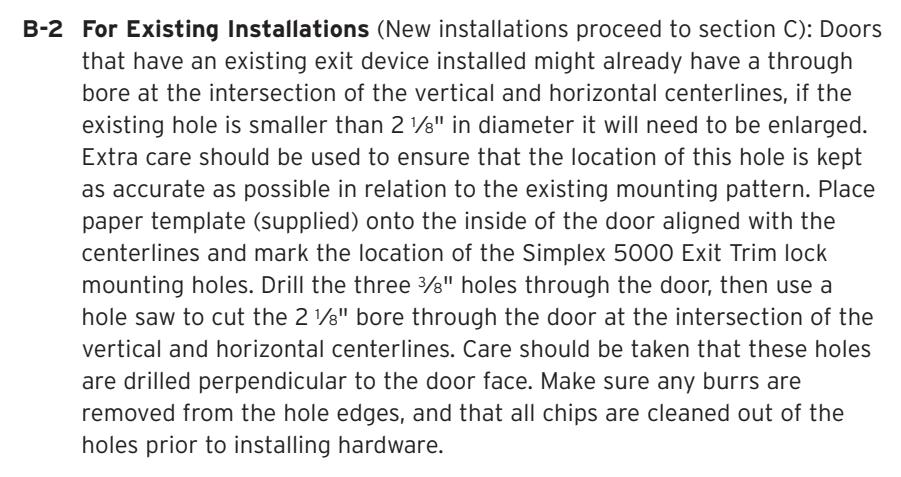
B. DOOR PREPARATION – SIMPLEX 5000 EXIT TRIM
B-1 For New Installations (Existing Installations proceed to section B-2): Place paper template (supplied) onto the inside of the door and align with the Centerlines. Mark the location of the Simplex 5000 Exit Trim lock mounting holes. Drill the three 3⁄8" holes through the door, then use a hole saw to cut the 2 1 ⁄8" bore through the door at the intersection of the Vertical and Horizontal Centerlines. Care should be taken that these holes are drilled perpendicular to the door face. Make sure any burrs are removed from the hole edges, and that all chips are cleaned out of the holes prior to installing hardware. d
C. INSTALL EXIT DEVICE:
Follow the exit device manufacturer's instructions for installing the exit device onto the door.
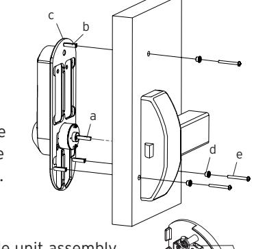
D. DOOR THICKNESS:
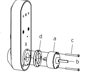
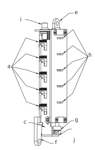
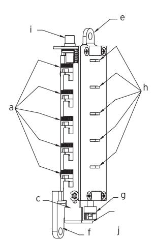
The Simplex 5000 Exit Trim lock drive unit (a) has a spring loaded tailpiece (b) and is preassembled to accommodate standard door thickness 1 3⁄4" to approximately 2 1 ⁄8" for most applications. For doors up to 2 1 ⁄4" it may be necessary to add a spacer to increase the projection of the tailpiece. If this is required, first remove and discard
a
e c
b
the two 1 3⁄8" (35mm) connecting screws (c) from the drive unit (a). Add spacer (d), and remount using the two longer 1 5⁄8" (41 mm) connecting screws supplied in the Thick Door Accessory Package.
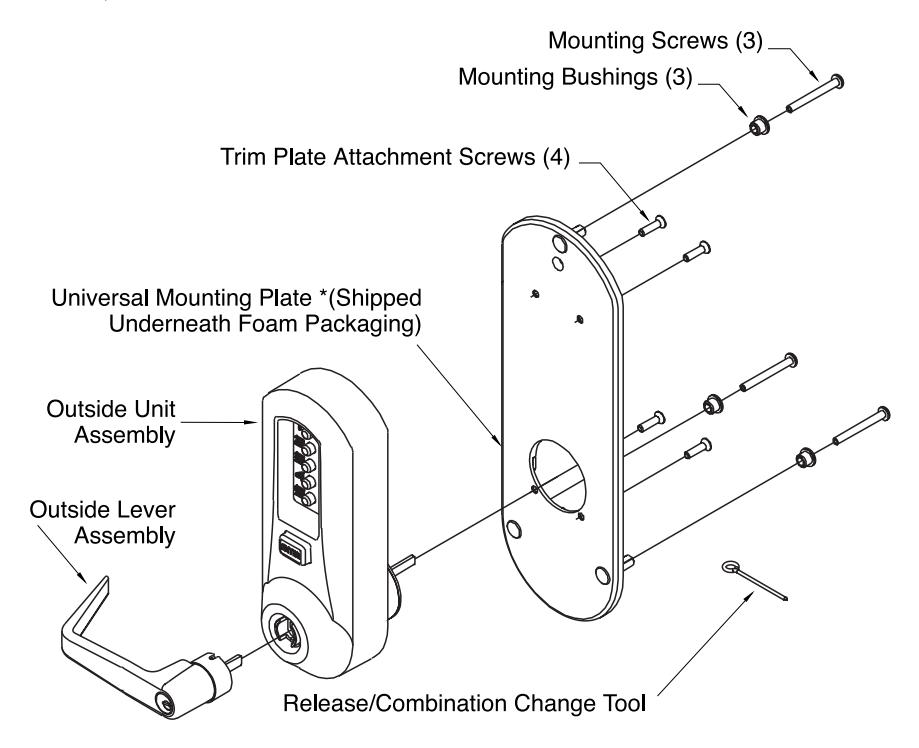
E. ASSEMBLE OUTSIDE UNIT TO UNIVERSAL MOUNTING PLATE:
Assemble the Universal Mounting Plate (a) to the Outside Unit Assembly (b) and secure using the (4) 10-24 x 3⁄4" long screws (c) supplied in the accessory kit.
F. LOCK HANDING:
F-1 Determine the handing of your door, from the following diagram.
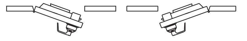
Left Hand Reverse Right Hand Reverse
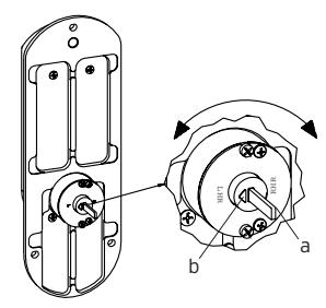
F-2 To set the handing of the drive unit grasp, the end of the tailpiece (a) between the fingers and rotate the tail piece until it stops with the indicator arrow (b) pointing at the stamped letter "LHR" for left hand reverse installations, or the stamped letter "RHR" for right hand reverse installations.
a
c e
d
f
b
Note: Until engaged with the exit device, the tailpiece (a) is free to swivel 180 degrees to facilitate handing of the lock. During shipping and preparation the position of the tailpiece may shift. The last step before mounting the lock unit is to make sure the drive unit is set up for proper rotation.
G. CHANGING KEY-IN-LEVER (KIL) CYLINDER:
The Simplex 5000 outside lever comes preassembled with Kaba's key-in-lever cylinder (Kaba 1599). To use a different key-in-lever cylinder follow remaining steps in this section.
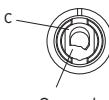
G-1 Remove KIL cylinder (a) from the outside lever (b) by removing the lever insert (e) and the cylinder retainer (c) using a small flat blade screw driver or small needle nose pliers. Remove the cylinder, then the tailpiece.
G-2 Determine the proper tailpiece (d) from the chart below for your KIL cylinder.
You must use a factory shortened Kaba tailpiece. The shortened K 2 tailpiece is preassembled with the Kaba 1599.
| TAILPIECE |
KIL
CYLINDER |
|---|---|
|
Abloy
5277, Abloy 5477, Assa 65691, Kaba 1539, Kaba Gemini 4730 |
|
|
Assa
65611, Australian: Kaba experT 107K5 & Boyd KC286, Corbin-Russwin 2000-03, Kaba 1599, Schlage 23-001, Schlage Primus 20-760, Kaba Peaks 1099 |
|
|
Medeco
20W200H1 |
|
|
Arrow
C100, Sargent 10 LINE |
|
| Marks |
G-3 Assemble the required tailpiece (d) (supplied with your KIL cylinder.
All tailpieces must be installed vertically for proper installation, as shown.
G-4 Insert the KIL cylinder into the outside lever (b) and secure it with the cylinder retainer (c) and cylinder insert (e) until the KIL cylinder is snug and unable to move freely.
H. INSTALLING / REMOVING OUTSIDE LEVER
(Key-In-Lever models only)(For interchangeable and removable cores proceed to section I)
Note: Installing levers to the unit assemblies before mounting the unit assemblies may ease initial installation.
d

b
Position
Incorrect Position
KIL Lever Sleeve
a
c e
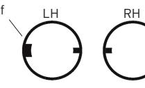
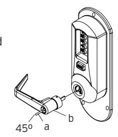
H-1 Make certain the lever catch is up as shown (c). Position the lever sleeve (f) tab correctly with the respective notch on the lever. The lock comes shipped with the lever sleeve already installed in the lock housing. When installing lever, ensure it is oriented to engage the lever sleeve to accommodate desired lock handing as shown.

H-3 Insert the outside lever (b) until it is flush to the outside unit assembly. Secure the outside lever by rotating the key clockwise 45 degrees to horizontal position. Remove key.
Note: To remove the outside lever from the outside unit assembly, follow the steps below.
H-4 Insert one of the (supplied) keys (a) into the outside lever (b) and rotate it counterclockwise 45 degrees. Insert release tool (d) into the small hole (e) under lever as shown. Gently push lever catch up until it clicks. Remove tool, then remove outside lever (b).
I. INSTALLING / REMOVING OUTSIDE LEVER
(Interchangeable / Removable Core Models)
Note: Installing lever to the unit assemblies before mounting the unit assemblies may ease initial installation.
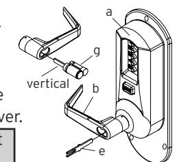
- I-1 Make certain the lever catch is up as shown (c). Position the lever sleeve (f) tab correctly with the respective notch on the lever. The lock comes shipped with the lever sleeve already installed in the lock housing. When installing the lever, ensure it is oriented to engage the lever sleeve to accommodate desired lock handing as shown.
- I-2 Insert the outside lever (b) until it is flush to the outside unit assembly (a). To secure the outside lever, insert the release tool (d) (or screw driver) into the outside lever as shown, and slide the lever catch down until it clicks. Make certain lever is attached before installing the core.

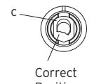
Correct Position Incorrect Position
LH RH f IC Lever Sleeve
KABA SIMPLEX®/E-PLEX® 5x00 SERIES LIMITED WARRANTY
Kaba Access Control warrants this product to be free from defects in material and workmanship under normal use and service for a period of three (3) years. Kaba Access Control will repair or replace, at our discretion, 5000 Series Locks found by Kaba Access Control analysis to be defective during this period. Our only liability, whether in tort or in contract, under this warranty is to repair or replace products that are returned to Kaba Access Control within the three (3) year warranty period.
This warranty is in lieu of and not in addition to any other warranty or condition, express or implied, including without limitation merchantability, fitness for purpose or absence of latent defects.
ATTENTION: This warranty does not cover problems arising out of improper installation, neglect or misuse. All warranties implied or written will be null and void if the lock is not installed properly and/or if any supplied component part is substituted with a foreign part. If the lock is used with a wall bumper, the warranty is null and void. If a doorstop is required, we recommend the use of a floor secured stop.
The environment and conditions of use determine the life of finishes on Kaba Access Control products. Finishes on Kaba Access Control products are subject to change due to wear and environmental corrosion. Kaba Access Control cannot be held responsible for the deterioration of finishes.
Authorization to Return Goods
Returned merchandise will not be accepted without prior approval. Approvals and Returned Goods Authorization Numbers (RGA Numbers) for the 5000 Series are available through our Customer Service department in Winston-Salem, NC (800) 849-8324. The serial number of a lock is required to obtain this RGA Number. The issuance of an RGA does not imply that a credit or replacement will be issued.
The RGA number must be included on the address label when material is returned to the factory. All component parts including latches and strikes (even if not inoperative) must be included in the package with return. All merchandise must be returned prepaid and properly packaged to the address indicated.
NO POSTAGE NECESSARY IF MAILED IN THE UNITED STATES

REPLY PERMIT NO. 1563 S S Ы Z FIRST-CLASS MAIL
BUS
POSTAGE WILL BE PAID BY ADDRESSEE
27199-3770 KABA ACCESS CONTROL 2941 INDIANA AVENUE WINSTON-SALEM, NC
| Check here if you would like more information on Kaba Access Control locks. | Lock Model Number | Purchased From | What was your reason for buying this lock? | ZIP (Postal Code) Country How did you learn about Kaba Access Control Pushbutton | Replacing a Keyless Lock other than Kaba | Address 🔲 Replacing a Kaba Electronic Access Control | Company Replacing a Kaba Mechanical Pushbutton Lock | This lock is: | register online at www.kabaaccess.com. What area is being secured with this lock? (e.g. Front Door, Common Door, Exercise Room) | This lock will be used in wh | ||||
|---|---|---|---|---|---|---|---|---|---|---|---|---|---|---|
| ountry | - |
better
stration |
. | |||||||||||
| ☐ Check here if you would like more | Locksmith | What was your reason for buying th | How did you learn about Kaba Acce | Replacing a Keyless Lock other tha | Replacing a Kaba Electronic Acces | Replacing a Kaba Mechanical Push | This lock is: | What area is being secured with thi | This lock will be used in what type o | |||||
| information on Kaba A | ■ Maintenance | is lock? | Training Class | ss Control Pushbutton I | in Kaba | Control | button Lock | Σ. | i lock? (e.g. Front Door, ( | Jfacturing | ||||
| ccess Control locks. | Other | Other (please specify) | Locks? | Common Door, Exercise Roon | School/Educational | Airport |
Note : For all interchangeable/removable cores except ASSA/Medeco/Yale, proceed to section I-3. For ASSA/Medeco/Yale cores, skip to section I-5.
I-3 Insert the supplied tailpiece (e) vertically into the outside lever (b) as shown. Make certain that you rotate the tailpiece so that it will align with the interchangeable core. For screw cap type cores (Schlage) (g), the tailpiece must be assembled to the core first (vertical position). Insert the interchangeable core into the outside lever. vertical
Note: To remove the outside lever from the outside unit assembly, follow the steps below.
I-4 Remove the interchangeable core (g). Then remove the tailpiece (e).
Note: You may want to use needle nose pliers for some tailpieces .

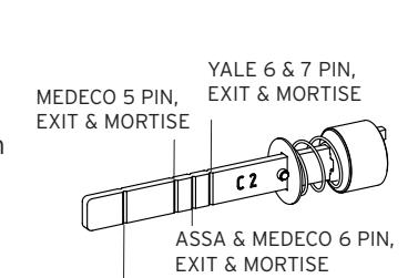
I-5 For ASSA/Medeco/Yale interchangeable/removable cores, the tailpiece must be prepped for the desired length before installation.
When using a Yale core on a cylindrical latch application, measure the door thickness of the intended application.
I-6 Notice the score marks on the flat portion of the ASSA/Medeco/Yale tailpiece. Using the diagram to the right, locate the score mark on your tailpiece that matches your core prep for the intended application, and break the tailpiece off accordingly.
Using two pairs of pliers, break the tailpiece to the desired length of the intended application by holding one pair of pliers on the good side of the score mark and a second pair on the other side of the score mark. Slowly move the 2nd pair of pliers up and down until the unneeded portion of the tailpiece breaks free.
I-7 Insert the ASSA/Medeco/Yale tailpiece (e) vertically into the outside lever as shown. Make certain that you rotate the tailpiece slightly so that it will align with the interchangeable/removable core. Insert the interchangeable/removable core into the outside lever.
Note : To remove the outside lever from the outside unit assembly, follow steps below.
e g
vertical
b
a
e
f
b
d
g
YALE 6 & 7 PIN, CYLINDRICAL – THIN DOOR (1 3⁄8" (35 mm) to 1 1 ⁄2" (38 mm)) (DO NOT SHORTEN TAILPIECE - For 1 5⁄8" (41 mm) to 2 1 ⁄4" (57 mm))
ASSA/MEDECO 5, 6 & 7 PIN, CYLINDRICAL – DO NOT SHORTEN TAILPIECE
I-8 Remove the interchangeable/removable core. Then remove the tailpiece (e).
Note : You may want to use needle nose pliers for some tailpieces.
I-9 Insert the lever release tool (d) into the small hole (f) under lever as shown. Gently push lever catch up until it clicks. Remove tool, then remove outside lever (b).
e g f d b vertical
b c
a
d e
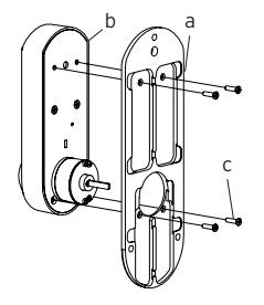
J. INSTALLING SIMPLEX 5000 EXIT TRIM:
Note: Prior to mounting the lock, ensure the handing is set correctly as the tailpiece may have shifted during handling (see section F)
- J-1 Guide the unit assembly so the tailpiece (a) engages the vertical slot in the hub of the exit device. The key override may be utilized to test the operation to make sure that the tailpiece is engaged with the exit device hub before fastening assembly to the door.
- J-2 Then insert the three mounting bushings (d) into the holes on the inside of the door, and thread the mounting screws (e) in to the sex bolts and tighten securely.
Note: Do not close the door until testing the operation of the lock and exit device as described in step K below .
K. TESTING THE OPERATION OF THE LOCK
- K-1 Depress the push pad of the exit device and hold. Ensure that the latch is fully retracted. Release the push pad; the latch should return to the fully extended position.
- K-2 Enter the factory set combination: Depress buttons 2 and 4 at the same time (& release), then press button 3 (& release), then depress the "ENTER" button and release . You should feel a slight click as each button is depressed.
- K-3 Rotate the outside lever downward and hold. Ensure that the latch is retracted sufficiently to clear the strike. Release the outside lever; the latch should be fully extended.
- K-4 Press the "ENTER" button only, and release, then rotate the outside lever. The latch should not retract.
K-5 Insert one of the supplied keys into the outside lever. Rotate key counter clockwise till it stops (approximately 90 degrees), while holding the key in this position with one hand, use the other hand to rotate the lever downwards till it stops and hold (once the lever has rotated a few degrees the key may be released). Ensure that the latch has retracted sufficiently to clear the strike. Release the lever once more and ensure that the latch is fully extended.
L. CHANGING COMBINATIONS
Note: The factory set combination of your new 5000 series: Press "2" and "4" at the same time, then release. Press "3", then release. Press the "ENTER" button, then release. For your security, the factory set combination MUST BE changed when lock is installed.
The combination can be easily changed using one to five of the lock's buttons in any order in the combination. Each button can only be used once. Note: Three or more non-sequential button combinations are recommended for higher security. Also, two or more buttons may be pushed together (at the same time) as part of your new combination.
CAUTION: The door MUST BE open during this entire procedure.
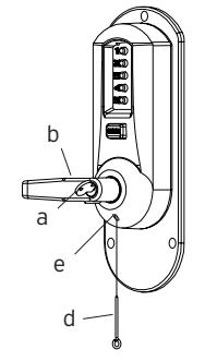
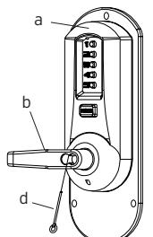
- L-1 Note: The combination change can be done without removing lock from door. Ensure that the door is open during this procedure. Rotate the outside lever (d) once to stop position and release to reset the lock; the latch should not retract.
- L-2 Press the existing combination (b) followed by the ENTER button (c) and release; do not turn the lever.
Exterior Combination Change
- L-3 Insert the release tool (a) through hole in number pad and gently lift up loop end of the tool to depress the code change button until you hear a click ; remove tool and do not press any buttons .
- L-4 **This Step Is Very Important** Rotate lever (d) once, and only once to clear the old combination; the latch (e) will retract; release the lever.
- L-5 Press in your new combination (b) followed by the ENTER button (c) and release.
- L-6 Rotate the lever (d) to verify that the latch retracts confirming the validity of the new combination (if you try the old combination now, it should not work).
IMPORTANT: The "ENTER" button must be depressed and released after entering the combination. The latch will not retract until the "ENTER" button is depressed and released.
M. HOW TO RESET A LOST OR UNKNOWN COMBINATION
There is no way to determine a forgotten, unknown or lost combination code from the front or outside of the lock. However, it can be reset and recovered or reset and changed to a new code by following the steps in this section.
Warning: Since this procedure is of a technical nature, only technically trained personnel in the lock and hardware field should undertake this operation. For further assistance, call the Kaba Access Control technical support line at 800-849-TECH (8324) or 336-725-1331 between 8AM and 5PM Eastern Standard Time, Monday through Friday (except holidays).
M-1 Removing Lock From Door
Remove the Simplex 5000 Exit Trim lock from the door. (Reverse procedures from section J of this manual).
M-2 Remove the Universal Mounting Plate from the Unit Assembly
Disassemble the Universal Mounting Plate from the Outside Unit Assembly. (Reverse procedure from section E of this manual).
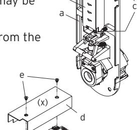
M-3 Removing Combination Chamber Assembly
Carefully remove the base plate of outside unit assembly (a) by removing the 2 Phillips screws (one screw may be found under an inspection sticker).
Remove the combination chamber assembly (b) from the base plate by removing the 2 Phillips screws (c).
Remove the 3-sided dust cover (d) to fully expose the chamber by removing 2 small Phillips screws (e) (may be 1 screw in newer models) (x).
b
M-4 Resetting and Recovery of Current Code
To reset the code gears (a), each one of the 5 "L" shaped legs (b) of the unlocking slide (c) must engage snugly with the corresponding code gear pocket (d) next to it.
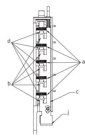
Position the chamber in one hand, as shown. Hold chamber by the top screw tab (e) and bottom screw tab (f).
Rotate the reset cam (g) back toward you with your finger, towards the key stems (h) as far as it will go and then release. Now look at the code gears (a) and the unlocking slide (c). Note that some or all 5
of the code gear pockets (d) are rotated away from the "L" shaped legs (b) as if out of alignment. Typically each code gear pocket will be at a slightly different distance compared to the other.
Note: Sometimes two different gear pockets are away from alignment by exactly the same distance – this indicates that the current code uses two different number buttons (example, 2 and 4) depressed at the same time as part of the code combination.
Using a small flat blade screw driver or your thumbnail, depress the key stem which corresponds to the gear pocket which has been rotated the farthest away (out of alignment) from the "L" shaped leg. When depressed, the key stem(s) should stay down and the corresponding gear pocket(s) should move closer to its corresponding "L" leg, closer to alignment. Record the key stem number. This is the first number of your combination.
Note: If two gear pockets are at the same distance , depress both of these corresponding key stems at the same time .
Continue by pressing the key stem that corresponds to the gear pocket that was the next furthest away (do not include gear pockets that have already been rotated). Record each key stem number that is depressed. Continue this procedure until all five gear pockets are aligned with their corresponding "L" shaped legs on the unlocking slide. The combination is the recorded numbers, in the order recorded.
Note: If you depress the wrong key stem by mistake, rotate the reset cam back toward you, (toward the key stems and release). This resets the code gears and you must repeat the above procedure.
M-5 Clearing the Current Code and Setting a New Code
Note: Align the code gear pockets with the "L" shaped legs.
Depress the code change button (i) located on top of the combination chamber once and release. Rotate the reset cam (g) back toward you with your finger (toward the key stems) as far as it will go and release.
Enter your new combination code by depressing the key stem corresponding to the first number (1 through 5) of your code. For example, if the new code is 3-2-5, then you would depress 3 first, then 2 and finally 5. Record this new combination code for future reference.
Push the shoulder (j) at the bottom of the Unlocking slide up toward the code change button and release.
If each of the 5 "L" shaped legs of the unlocking slide engages snugly inside its corresponding code gear pocket, then it confirms that the new code has been successfully changed. Rotate the reset cam (g) back toward you and release.
Note: If all 5 "L" shaped legs do not align fully with their corresponding code gear pockets, repeat the procedures M-3 and M-4.
M-6 Reinstalling chamber assembly into lock and retesting
Reinstall the 3-sided dust cover over the combination chamber with the 2 small Phillips screws removed (maybe 1 screw in newer models). Reinstall the combination chamber assembly to the base plate with the 2 Phillips screws removed.
Reinstall the base plate on to the outside unit assembly with the 2 Phillips screws removed. Make sure all parts have been reinstalled correctly.
Then reinstall the universal mounting plate with 2 Phillips screws removed earlier.
- M-7 Reinstall lock on door by following procedures outlined in section J of this manual.
- M-8 Retest new code with lock on door by entering the new numbers followed by the "ENTER" button and rotating the outside lever. The lock should open and the latch should retract.
N. TROUBLE SHOOTING
| SYMPTOM |
POSSIBLE
CAUSE |
REMEDY | ||
|---|---|---|---|---|
|
1.
The outside lever always retracts the latch after depressing and releasing the "ENTER" button only (without combination). |
Lock
is in "ZERO" combination. |
Follow
the procedure for Changing Combinations (Section M) except omit steps 1 and 2 (do not enter the existing combination). |
||
|
2.
The outside lever will not go completely inside the outside unit assembly. |
Lever
catch is misaligned. |
Insert
release tool through small hole on the outside unit assembly (under the lever). Using the tool, gently lever push catch up until it clicks. Refer to Section I or J (Installing and Removing the Outside Lever). |
||
|
3.
Correct combination is depressed but the latch does not retract. |
Failed
to depress the "ENTER" button. |
Always
depress and release the "ENTER" button after depressing the correct combination. |
||
|
4.
Cannot remove key from outside lever — key is stuck. |
Key
was rotated 180 degrees in wrong direction. |
Rotate
key counterclock wise. Insert release tool through small hole on the outside unit assembly (under the lever). Using the tool gently push lever catch up until it clicks. Remove outside lever. Remove key. Then follow steps in Section I or J: Installing and Removing the Outside Lever. |
||
| SYMPTOM |
POSSIBLE
CAUSE |
REMEDY |
|---|---|---|
|
5.
The outside lever does not retract the latch after entering the correct combina tion and depressing the enter button. |
The
drive unit handing was not set correctly, or the tailpiece is not engaged with the exit device hub. |
Remove
lock from door and refer to section F. Make sure the drive unit handing is set correctly. Also, check door thick ness; if the door is over 2" thick make sure the tail piece projection is ade quate to engage the exit device hub. Refer to sec tion D to adjust for door thickness. Remount unit taking care to ensure the tailpiece engages the exit device hub properly. (This is a blind operation, but the spring-loaded tailpiece should make an audible click when it pops in to place, use the key over ride function to make sure the latch retracts when the lever is rotated before securing mounting screws). |
| Notes | Notes |
|---|---|