Simplex 5000 Series Cylindrical Installation Instructions
Open the original PDF document
View PDF

INSTALLATION INSTRUCTIONS SIMPLEX® 5000 CYLINDRICAL
TABLE OF CONTENTS
|
Exploded
Install Parts .3 |
|
|---|---|
| Tools |
Required
.3 |
| A. |
Door
Preparation .4 |
| B. |
Lock
Handing .4 |
| C. |
Door
Thickness .5 |
| D. |
Installing
The Passage Set .5 |
| E. |
Installing
Outside Unit Assembly .6 |
| F. |
Installing
Inside Unit Assembly .6 |
| G. |
Installing
The Inside Lever/Knob .7 |
| H. |
Changing
Key-In-Lever/Knob (KIL/KIK) Cylinder .7 |
| I. |
Installing/Removing
Outside Lever/Knob (KIL/KIK models only) .8 |
| J. |
Installing/Removing
Outside Lever/Knob .9 |
|
(Interchangeable/Removable
Core models) |
|
| K. |
Testing
The Operation Of The Lock .15 |
| L. |
Installing
The Strike .16 |
| M. |
Changing
Combinations .16 |
| N. |
Installing
Rubber Bumpers .18 |
| O. |
How
To Reset A Lost Or Unknown Combination .18 |
| P. |
Trouble
Shooting .21 |
|
Notes
.23 |
OPERATION
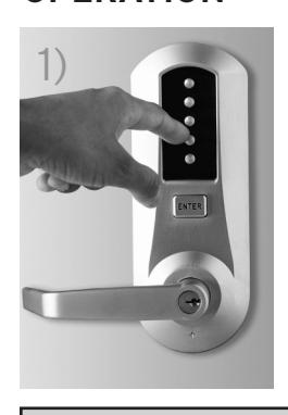
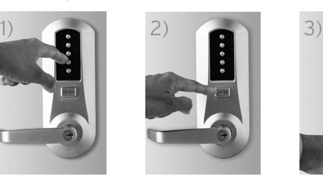
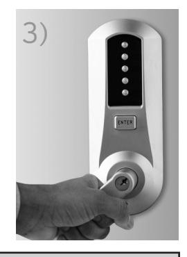
Warning
The combination of this lock has been factory preset; 2 and 4 depressed at the same time, then 3 and then ENTER. For your security, the combination must be changed at time of installation.
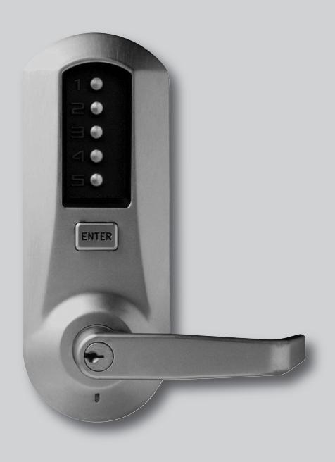
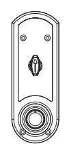
Model 502x (shown)
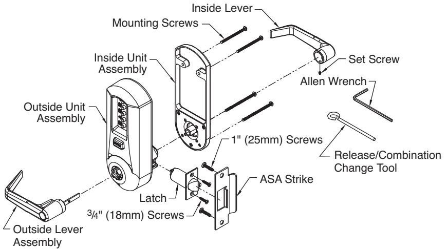
The Simplex 5000 is a non-handed lock that is preassembled for left-hand installations. It is field reversible.
TOOLS REQUIRED
- Safety glasses
- Electric drill (variable speed)
- Awl or center punch
- 2 1 ⁄8" (54 mm) hole saw pilot drill
- 1" (25 mm) hole saw pilot drill
- 1 ⁄4" (7 mm) drill bit
- 1" (25 mm) wood chisel
- Hammer
- Phillips head screw driver
- Small flat blade screwdriver
Warnings and Cautions
Important : Carefully inspect windows, door frame, door, lights, etc., to ensure that the recommended procedures will not cause damage. Kaba Access Control's warranty does not cover damages caused by installation.
Caution : Wear safety glasses when preparing door.

For technical assistance please call 1.800.849.TECH (8324) or 336.725.1331
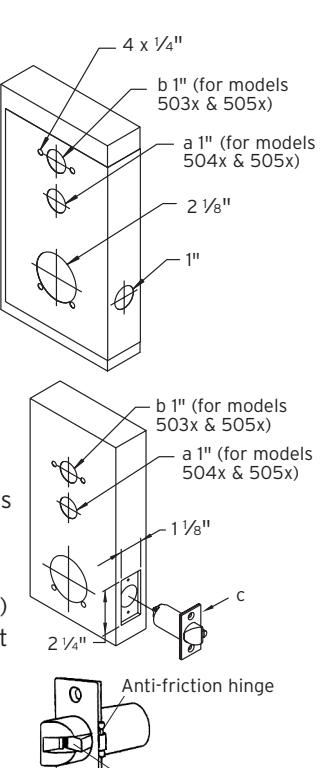
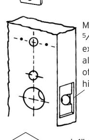
A. DOOR PREPARATION
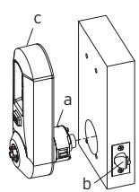
- A-1 Place paper template (supplied) onto door and mark for holes. Drill the four 1 ⁄4" (7 mm) holes first. Next drill the 2 1 ⁄8" (54 mm) cross bore hole. Drill the 1" (25 mm) hole last.
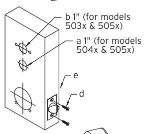
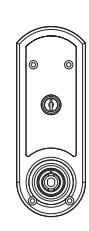
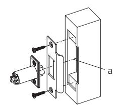
- A-2 For Models 504x & 505x only. When installing Model 502x, skip to step A-4 . Passage feature models require an additional 1" (25 mm) hole in the door face (see "a" in the illustration to the right).
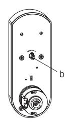
- A-3 For Models 503x & 505x only. When installing Models 502x or 504x models, skip to step A-4 . Inside code change models require an additional 1" (25 mm) hole in the door face (see "b" in the illustration).
- A-4 Mortise door edge for latch unit faceplate (c) 1 ⁄8" (3 mm) deep to dimensions shown. Insert latch unit into the 1" (25 mm) hole, making certain that the latch bolt bevel faces direction of closing door.
Note : If using a 3⁄4" (19 mm) latch, the edge of the latch bore hole must be prepped to accomodate the anti-friction hinge. (The location of the antifriction hinge depends on the door handing).
A-5 Secure the latch to the door using two 3⁄4" (19 mm) combination screws (d) supplied. Latch unit faceplate must be flush with door (e).
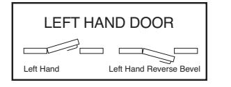
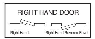
B. LOCK HANDING
The Simplex 5000 is a non-handed lock that is preassembled for left-hand door installations.
B-1 Determine the hand of your door. For left hand doors, proceed to Section C. For right hand doors, follow steps in B-2.
Mortise approx. 5⁄16" (8 mm) extra depth to allow clearance of anti-friction hinge
Anti-friction device
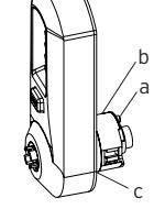
B-2 Remove the two connecting screws (a) from the cylindrical drive unit (b). Rotate cylindrical drive unit 180 degrees. Reposition spacer (c) as found before disassembly. Remount drive unit with the two connecting screws.
C. DOOR THICKNESS
The Simplex 5000 lock is preassembled to accommodate standard door thickness 1 5⁄8" (41 mm) to 2" (51 mm).
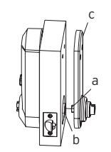
- C-1 (Reference Figure A) For thinner door applications of 1 3⁄8" (35 mm) to 1 1 ⁄2" (38 mm) Remove and discard the two connecting screws (a) from the cylindrical drive unit (b). Remove and discard the spacer (c). Remount the cylindrical drive unit using the two shorter 1 3⁄8" (35 mm) connecting screws supplied.
- C-2 (Reference Figure B) For thicker door applications of 2 1 ⁄8" (54mm) to 21 ⁄4" (57mm) Remove the two connecting screws (a) from thecylindrical drive unit (b). Add the extra spacer(c) supplied. Remount the cylindrical drive unitusing the same two connecting screws (a) just removed. (Do not over tighten screws)
D. INSTALLING THE PASSAGE SET
For models 504x & 505x only. When installing non-passage models, skip to section E.
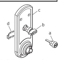
Note: The end user may choose either a key cylinder (a) or turn knob (b) actuator to engage the passage function.
D-1 Prior to installing the passage actuator, hold the chosen actuator housing in one hand, and with the other hand, rotate the key cylinder or knob counterclockwise until it stops. If the key cylinder actuator is used, withdraw the key, which will lock the cylinder in this position (a detent in the turn knob locks the cylinder).
b a
b a c
c
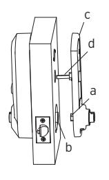
- D-2 Insert the key cylinder or turn knob assembly (a or b) into the opening on the inside unit assembly (c). Upon completion, the arrow of the turn knob should be pointing to the left, or the dot on the face of the key cylinder actuator should be on the left.
- D-3 Secure the passage set assembly with the spring clip (d) from the inside.
D-4 Rotate the knob or key cylinder (re-insert key at this point) clockwise to test the rotation. If properly installed, the knob or key cylinder should rotate 90 degrees clockwise so that the arrow (knob) is pointing up or the dot (key cylinder) is at the top.
Note: Leave the actuator set in this position for installation (if key cylinder is used, remove the key at this point).
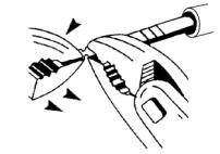
Note: The tailpiece of the passage actuator is scored on several places to allow you to easily break off the section that extends beyond the required length to engage the passage set cam.
D-5 Hold the tailpiece firmly with a pair of pliers, adjacent to the desired break line. With a second pair of pliers, grip the tailpiece on the other side of the scored line and bend up and down until it breaks.
E. INSTALLING OUTSIDE UNIT ASSEMBLY
Note: Installing levers/knobs to the unit assemblies before mounting the unit assemblies may ease initial installation.
E-1 For models 504x & 505x only. When installing nonpassage models, skip to step E-2 . Ensure that the passage cam (b) is rotated counterclockwise until it stops. When complete, the slot will be vertical.
E-2 Slide the drive unit (a) into 2 1 ⁄8" (54 mm) cross bore hole by depressing latch bolt (b) in slightly until the outside unit assembly (c) rests flush against the door.
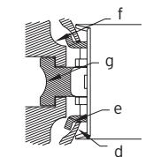
E-3 The drive unit (d) must engage the latch unit prongs (e) and the shoe retractor (f) must engage the latch unit tailpiece (g) as shown.
F. INSTALLING INSIDE UNIT ASSEMBLY
Note: Installing levers/knobs to the unit assemblies before mounting the unit assemblies may ease initial installation.
F-1 For Models 504x & 505x only. When installing nonpassage models, skip to step F-2 . Slide the drive hub (a) into the sleeve (b), and the passage tailpiece (d) into the passage cam slot until the inside unit assembly (c) rests flush against the door.
F-2 Slide the drive hub (a) into the drive sleeve (b) until the inside unit assembly (c) rests flush against the door.
F-3 For standard door thickness 1 5/8" (41 mm) to 2" (51 mm), secure the outside and inside unit assemblies to the door by using four 2 7/8" (73 mm) screws (d) (supplied) in all four holes as indicated.
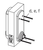
For thinner door 1 " (35 mm) to 1 " (38 mm), secure the outside and inside unit assemblies to the door by using four 2 " (64 mm) screws (e) (supplied) in all four holes as indicated.
For thicker door " (54 mm) to " (57 mm), secure the outside and inside unit assemblies to the door by using four " (82mm) screws (f) (supplied) in all four holes as indicated.
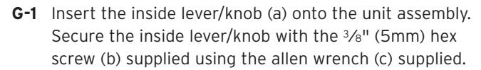
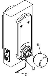
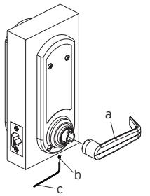
G. INSTALLING THE INSIDE LEVER/KNOB
Note: Installing the lever/knob assemblies to the unit before mounting the unit assemblies, may ease initial installation.
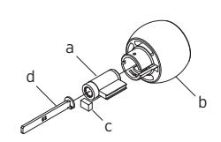
H. CHANGING KEY-IN-LEVER/KNOB CYLINDER
The Simplex 5000 outside lever/knob comes preassembled with Kaba's key-in-lever/knob cylinder (Kaba 1599). To use a different key-in-lever/knob cylinder, follow the remaining steps in this section.
H-1 Remove KIL/KIK cylinder (a) from the outside lever/knob (b) by removing the lever insert (e) (no insert on knob). Remove the rubber cylinder retainer (c) using a small screwdriver or needle nose pliers.
| TAILPIECE |
KIL/KIK
CYLINDER |
|---|---|
| K1 |
Abloy
5277, Abloy 5477, Assa 65691, Kaba 15396, Kaba Gemini 4730 |
| K2 |
Assa
65611, Australian: Kaba experT 107K5 & Boyd KC286, Corbin-Russwin 2000-03, Kaba 1599, Schlage 23-001, Schlage Primus 20-760, Kaba Peaks 1099 |
| K3 |
Medeco
20W200H1 |
| K4 |
Arrow
C100, Sargent 10 LINE |
| K5 | Marks |
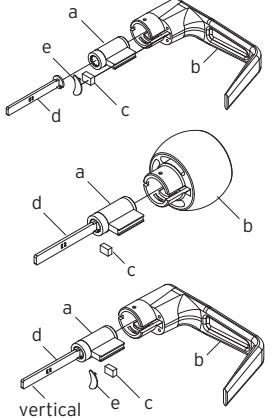
H-2 Determine the proper tailpiece (d) needed for your KIL/KIK cylinder from the chart above.
You must use a KABA tailpiece. The K-2 tailpiece is preassembled with the 1599 cylinder.
- H-3 Assemble the required tailpiece (d) supplied with your KIL/KIK cylinder. All tailpieces must be installed vertically as shown for proper installation.
- H-4 Insert the KIL/KIK cylinder (a) into the outside lever/knob (b) and secure it with the cylinder retainer (c) and lever insert (e) (no insert on the knob). The KIL/KIK cylinder should be snug and unable to move freely.
I. INSTALLING/REMOVING OUTSIDE LEVER/KNOB
(Key-in-Lever/Knob Models only) (For interchangeable and removable cores, proceed to section J)
Note: Installing lever/knob to the unit assemblies before mounting the unit assemblies, may ease initial installation.
c
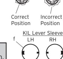
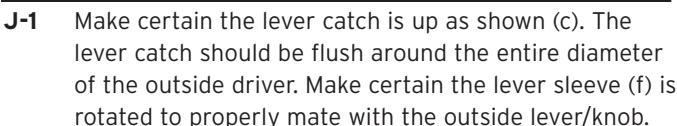
I-1 Make certain the lever catch is up as shown (c). The lever catch should be flush around the outer diameter of the outside driver. Make certain the lever sleeve (f) is rotated to properly mate with the outside lever/knob.

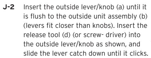
I-3 Insert the outside lever/knob (b) until it is flush to the outside unit assembly (levers fit closer than knobs). Secure the outside lever/knob by rotating the key clockwise 45 degrees to the horizontal position. Remove key. 45º
Note: To remove the outside lever/knob from the outside unit assembly, follow steps below.
I-4 Insert one of the supplied keys (a) into the outside lever/knob and rotate it counterclockwise 45 degrees. Insert the release tool (d) into the small hole (e) under the lever/knob as shown. Gently push the lever catch up until it clicks. Remove tool, then remove the outside lever/knob.
a
b
J. INSTALLING/REMOVING OUTSIDE LEVER/KNOB
(Interchangeable/Removable Core Models)
Note: Installing levers/knobs to the unit assemblies before mounting the unit assemblies, may ease initial installation.
Note : For all interchangeable/removable cores except ASSA/Medeco/Yale, proceed to section J-3. For ASSA/Medeco/Yale cores, skip to section J-5.
Correct Position
b
a
Incorrect Position
IC Lever Sleeve LH RH f
KABA SIMPLEX®/E-PLEX® 5x00 SERIES LIMITED WARRANTY
Kaba Access Control warrants this product to be free from defects in material and workmanship under normal use and service for a period of three (3) years. Kaba Access Control will repair or replace, at our discretion, 5000 Series Locks found by Kaba Access Control analysis to be defective during this period. Our only liability, whether in tort or in contract, under this warranty is to repair or replace products that are returned to Kaba Access Control within the three (3) year warranty period.
This warranty is in lieu of and not in addition to any other warranty or condition, express or implied, including without limitation merchantability, fitness for purpose or absence of latent defects.
ATTENTION: This warranty does not cover problems arising out of improper installation, neglect or misuse. All warranties implied or written will be null and void if the lock is not installed properly and/or if any supplied component part is substituted with a foreign part. If the lock is used with a wall bumper, the warranty is null and void. If a doorstop is required, we recommend the use of a floor secured stop.
The environment and conditions of use determine the life of finishes on Kaba Access Control products. Finishes on Kaba Access Control products are subject to change due to wear and environmental corrosion. Kaba Access Control cannot be held responsible for the deterioration of finishes.
Authorization to Return Goods
Returned merchandise will not be accepted without prior approval. Approvals and Returned Goods Authorization Numbers (RGA Numbers) for the 5000 Series are available through our Customer Service department in Winston-Salem, NC 800.849.8324. The serial number of a lock is required to obtain this RGA Number . The issuance of an RGA does not imply that a credit or replacement will be issued.
The RGA number must be included on the address label when material is returned to the factory. All component parts including latches and strikes (even if not inoperative) must be included in the package with return. All merchandise must be returned prepaid and properly packaged to the address indicated.

NO POSTAGE NECESSARY IF MAILED IN THE UNITED STATES

BUSINESS REPLY MAIL FIRST-CLASS MAIL PERMIT NO. 1563 WINSTON-SALEM, NC
POSTAGE WILL BE PAID BY ADDRESSEE
KABA ACCESS CONTROL 2941 INDIANA AVENUE WINSTON-SALEM, NC 27199-3770
REGISTRATION CARD
This lock will be used in what type of
facility?
Thank
protect your investment and to enable us to better serve you in the future, please fill out this registration card and return it to Kaba Access Control, or register online at www.kabaaccess.com
Name Position Company Address
City State
Phone Email Name of
Date of
Lock
Model
|
Ac
ce ss Co nt ro l loc ks |
inf
or m at ion on Ka ba |
ul
d lik e m or e |
if
wo |
❏
Ch ec k he re |
|||
|---|---|---|---|---|---|---|---|
|
❏
Ot he r |
❏
Ma int en an ce |
❏
Lo ck sm ith |
Nu
m be r |
||||
|
ur
loc k? |
W
ho in st al led yo |
ha
se |
Pu
rc |
||||
|
ale
r Pu rc ha se d Fro m |
De | ||||||
|
loc
k? |
fo
r bu yi ng th is |
re
as on |
W
ha t wa s yo ur |
||||
|
❏
Ot he r (p lea se sp ec ify ) |
❏
Tr ain ing Cl as s |
Ma
int en an ce |
❏ |
❏
Lo ck sm ith |
|||
|
Lo
❏ ck s? An ot he r Us e |
Co
❏ nt Int ro l er Pu ne sh t/W bu eb tt on |
t
Pr Ka ev iou ba s Ac Us ce e ss |
rn
t ab ❏ ou |
❏
Ho w Ad di ve d rti yo se u m lea en |
Co
un try |
ZI
P (P os ta l Co de ) |
|
|
Ka
ba |
Lo
ck ot he r th an |
Ke
yle ss |
❏
Re pla cin g a |
||||
|
Co
nt ro l |
ct
ro nic Ac ce ss |
Ka
ba Ele |
❏
Re pla cin g a |
||||
|
bu
tto n Lo ck |
ch
an ica l Pu sh |
Ka
ba Me |
❏
Re pla cin g a |
||||
|
na
l ke ye d loc k |
co
nv en tio |
❏
Re pla cin g a |
|||||
|
tio
n |
❏
Ne w Ins ta lla |
||||||
|
Th
is loc k is: |
|||||||
|
Co
m m on Do or , Ex er cis e Ro om ) |
loc
k? (e. g. Fro nt Do or , |
re
d wi th th is |
in
g se cu |
W
ha t ar ea is be |
om
ro or |
lin
e rn at w w w. ka ba ac ce ce ss ss .c |
on
re |
|
(p
lea se sp ec ify ) |
❏
Ot he r |
alt
hc ar e |
❏
Ho sp ita l/ He |
th
nt is re l, gi st ra tio n |
tu
th e fu it tu to re Ka , pl ba ea Ac se fil l ou Co t |
in | |
|
Sc
ho ol /E du ca tio na l |
m
en t/ Mi lita ry ❏ |
❏
Go ve rn |
er
sit y |
❏
Co lle ge /U niv |
le
us to be tt er |
ur
in ve st m en t an d to en ab |
yo |
|
Ai
rp or t |
al/
Ma nu fa ct ur ing ❏ |
❏
Ind us tri |
Bu
ild ing |
❏
Co m m er cia l |
uc
t. In or de r to |
fo
r pu rc ha si ng ou r pr od |
yo
u |
here if you would like more
| Notes | ||
|---|---|---|
J-3 Insert the supplied tailpiece (e) with the flat installed vertically into the outside lever/knob (b) as shown. Make certain you rotate the tailpiece so that it aligns with the rear of the core. For screw cap type cores (Schlage) (g), the tailpiece must be assembled to the core first, with the tailpiece vertically as shown. Insert the core into the outside lever/knob. e
Note: To remove the outside lever/knob from the outside unit assembly, follow the steps below.
J-4 Remove the interchangeable core (a). Then remove the tailpiece (b).
Note: You may want to use needle nose pliers for some tailpieces.
Insert the release tool (d) into the small hole (f) under the lever/knob as shown. Gently push lever/knob catch up until it clicks. Remove tool, then remove outside lever/knob (b).
J-5 For ASSA/Medeco/Yale interchangeable/ removable cores, the tailpiece must be prepped for the desired length before installation.
b b f d f d MEDECO 5 PIN, EXIT & MORTISE YALE 6 & 7 PIN, EXIT & MORTISE
b
b
b
a
g
a
vertical
b
e
Note: When using a Yale core on a cylindrical latch application, measure the door thickness of the intended application.
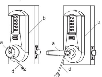
J-6 Notice the score marks on the flat portion of the ASSA/Medeco/Yale tailpiece. Using the diagram to the right, locate the score mark on your tailpiece that matches your core prep for the intended application, and break the tailpiece off accordingly.
Note: Using two pairs of pliers, break the tailpiece to the desired length of the intended application by holding one pair of pliers on the good side of the score mark and a second pair on the other side of the score mark. Slowly move the second pair of pliers up and down until the unneeded portion of the tailpiece breaks free.
YALE 6 & 7 PIN, CYLINDRICAL – THIN DOOR (1 3⁄8" (35 mm) to 1 1 ⁄2" (38 mm)) (DO NOT SHORTEN TAILPIECE - For 1 5⁄8" (41 mm) to 2 1 ⁄4" (57 mm))
ASSA/MEDECO 5, 6 & 7 PIN, CYLINDRICAL – DO NOT SHORTEN TAILPIECE
J-7 Insert the ASSA/Medeco/Yale tailpiece (e) vertically into the outside lever/knob as shown. Make certain that you rotate the tailpiece slightly so that it will align with the interchangeable/removable core. Insert the interchangeable/removable core into the outside lever/knob.
Note : To remove the outside lever/knob from the outside unit assembly, follow steps below.
J-8 Remove the interchangeable/removable core. Then remove the tailpiece (e).
Note : You may want to use needle nose pliers for some tailpieces.
J-9 Insert the lever release tool (d) into the small hole (f) under lever/knob as shown. Gently push lever catch up until it clicks. Remove tool, then remove outside lever/ knob (b).
K. TESTING THE OPERATION OF THE LOCK
- K-1 Rotate inside lever/knob and hold. Ensure that the latch is fully retracted and flush with the latch faceplate. Release the inside lever/knob; the latch should be fully extended.
- K-2 For Models 504x & 505x only. When installing non-passage models, skip to step K-4. Ensure that the key cylinder or knob of the passage actuator is set so that the arrow or dot is at the top. Rotate outside lever/knob and hold. Ensure that the latch is fully retracted and flush with the latch faceplate. Release outside lever/knob: the latch should be fully extended.
- K-3 Rotate passage actuator counterclockwise so that the arrow or dot is to the left. Then rotate outside lever/knob. The latch should not move.
- K-4 Enter the factory-set combination: Depress buttons 2 and 4 at the same time (& release), then depress button 3 (& release), then depress the "ENTER" button (& release) . You should feel a slight click as each button is depressed.
- K-5 Rotate outside lever/knob and hold. Ensure that the latch is fully retracted and flush with the latch faceplate. Release the outside lever/knob; the latch should be fully extended. Press the "ENTER" button and release, then rotate outside lever/knob. The latch should NOT retract.
- K-6 Insert one of the (supplied) keys into the outside lever/knob. Rotate key counterclockwise to stop position and hold. Ensure that the latch is fully retracted and flush with the latch faceplate. Rotate key clockwise to horizontal position and remove key. The latch should be fully extended.
f
d
f
b
b
e
e
d
L. INSTALLING THE STRIKE
Note: The latch and strike provided must be used .
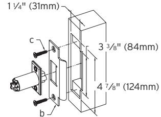
- L-1 Mark location of strike on the door frame, making certain that the strike opening is aligned (a) with the latch bolt.
- L-2 Mortise doorframe for strike 3⁄32" (3 mm) deep minimum to dimensions shown. Secure strike (b) to the door frame using two 1" (25 mm) combination screws (c) (supplied).
M. CHANGING COMBINATIONS
Note: The factory set combination of your new 5000 series: Press "2" and "4" at the same time, then release. Press "3", then release. Press the "ENTER" button, then release. For your security, the factory set combination MUST BE changed when lock is installed.
The combination can be easily changed using one to five of the lock's buttons in any order in the combination. Each button can only be used once. Note: Three or more non-sequential button combinations are recommended for higher security. Also, two or more buttons may be pushed together (at the same time) as part of your new combination.
CAUTION: The door MUST BE open during this entire procedure.
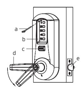
Note: The combination change can be done without removing lock from door. Ensure that the door is open during this procedure. Rotate the outside lever/knob (d) once to stop position and release to reset the lock the latch should not retract.
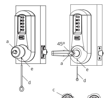
M-1 Press the existing combination (b) followed by the ENTER button (c) and release; do not turn the lever/knob.
Note: Determine if you have an interior/exterior code change, and follow appropriate procedure below.
Exterior Combination Change
M-2 Insert the release tool (a) through hole in number pad and gently lift up loop end of the tool to depress the code change button until you hear a click ; remove tool and do not press any buttons (proceed to M-4).
Interior Combination Change
- M-3 Unscrew special torx screw from inside housing using supplied torx wrench. Enter your existing combination, and depress and release the "ENTER" button. Insert longer end of the same torx wrench through the opening until it engages with the mating part. Turn wrench counterclockwise (using minimal force) approximately 90 degrees, until it clicks. Return wrench to initial position. Remove wrench and replace torx screw.
- M-4 **This Step Is Very Important** Rotate lever/ knob (d) once, and only once to clear the old combination; the latch (e) will retract; release the lever/knob.
- M-5 Press in your new combination (b) followed by the ENTER button (c) and release.
- M-6 Rotate the lever/knob (d) to verify that the latch (e) retracts confirming the validity of the new combination (if you try the old combination now, it should not work).
IMPORTANT: The "ENTER" button must be depressed and released after entering the combination. The latch will not retract until the "ENTER" button is depressed and released.
COMBINATION SETTING RECORD
| Combination |
&
ENTER |
Date |
|
&
ENTER |
||
|
&
ENTER |
||
|
&
ENTER |
||
|
&
ENTER |
||
|
&
ENTER |
||
|
&
ENTER |
||
|
&
ENTER |
||
|
&
ENTER |
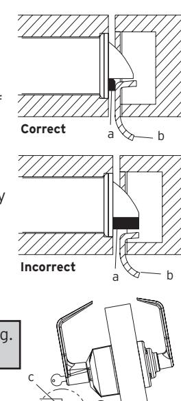
Caution: Check the operation of the latch by making sure that the deadlatch (a) stops against the strike (b) as shown and does not slide into the strike opening when the door is closed. If that situation occurs, then a total lockout may occur. This will void our warranty of the complete lock mechanism. If necessary, correct the door over-travel by using the rubber bumpers as described in Section N (Installing Rubber Bumpers).
N. INSTALLING RUBBER BUMPERS
- N-1 Close the door and apply pressure making sure the deadlatch (a) rests on the strike plate (b) as shown. Standing on the frame (door stop) side of the door, check for gaps between the door and the frame on the three sides of the frame (left, right, and top).
- N-2 Mark locations where the gaps are approximately 3⁄16" (5 mm). Make sure these locations are free from grease and dust. Peel the bumpers (c) (supplied) from their protective backing without touching the adhesive surface and stick them on the marked locations.
Note: Allow 24 hours for adhesive to set before testing. The door may be operated normally during this time.
O. HOW TO RESET A LOST OR UNKNOWN COMBINATION
There is no way to determine a forgotten, unknown or lost combination from the front or outside of the lock. However, it can be reset and recovered or reset and changed to a new combination by following the steps in this section.
Warning: Since this procedure is of a technical nature, only technically trained personnel in the lock and hardware field should undertake this operation. For further assistance, call the Kaba Access Control technical support line at
800-849-TECH (8324) or 336-725-1331 between 8AM and 5PM Eastern Standard Time, Monday through Friday (except holidays). a
O-1 Removing Lock From Door
Remove both the outside unit assembly (a) and the inside unit assembly (b). (Reverse procedures from sections E and F of this manual.)
O-2 Removing Combination Chamber Assembly
Carefully remove the base plate of outside unit assembly (a) by removing the 2 Phillips screws (one screw may be found under an inspection sticker).
Remove the combination chamber assembly (b) from the base plate by removing the 2 Phillips screws (c).
Remove the 3-sided dust cover (d) to fully expose the chamber by removing 2 small Phillips screws (e). (May be 1 screw (x) in newer models)
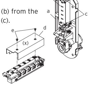
b
b
O-3 Resetting and Recovery of Current Combination
To reset the code gears (a), each one of the 5 "L" shaped legs (b) of the unlocking slide (c) must engage snugly with the corresponding code gear pocket (d) next to it.
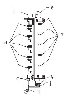
Position the chamber in one hand, as shown. Hold chamber by the top screw tab (e) and bottom screw tab (f).
Rotate the reset cam (g) back toward you
with your finger, towards the key stems (h) as far as it will go and then release. Now look at the code gears (a) and the unlocking slide (c). Note that some or all 5 of the code gear pockets (d) are rotated away from the "L" shaped legs (b) as if out of alignment. Typically each code gear pocket will be at a slightly different distance compared to the other.
Note: Sometimes two different gear pockets are away from alignment by exactly the same distance – this indicates that the current combination uses two different number buttons (example, 2 and 4) depressed at the same time as part of the combination.
Using a small flat blade screw driver or your thumbnail, depress the key stem which corresponds to the gear pocket which has been rotated the farthest away (out of alignment) from the "L" shaped leg. When depressed, the key stem(s) should stay down and the corresponding gear pocket(s) should move closer to its corresponding "L" leg, closer to alignment. Record the key stem number. This is the first number of your combination.
Note: If two gear pockets are at the same distance , depress both of these corresponding key stems at the same time .
Continue by pressing the key stem that corresponds to the gear pocket that was the next furthest away (do not include gear pockets that have already been rotated). Record each key stem number that is depressed. Continue this procedure until all five gear pockets are aligned with their corresponding "L" shaped legs on the unlocking slide. The combination is the recorded numbers, in the order recorded.
Note: If you depress the wrong key stem by mistake, rotate the reset cam back toward you, (toward the key stems and release). This resets the code gears and you must repeat the above procedure, O-3.
a
c j
b
d
O-4 Clearing the Current Combination and Setting a New Combination
Note: Align the code gear pockets with the "L" shaped legs.
Depress the combination change button (i) located on top of the combination chamber and release.
Rotate the reset cam back toward you with your finger (toward the key stems) as far as it will go and release.
Enter your new combination by depressing the key stem corresponding to the first number (1 through 5) of your combination. For example, if the new combination is 3-2-5, then you would depress 3 first, then 2 and finally 5. Record this new combination for future reference.
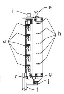
Push the shoulder (j) at the bottom of the Unlocking slide up toward the combination change button and release. If each of the 5 "L" shaped legs of the unlocking slide engages snugly inside its corresponding code gear pocket, then it confirms that the new combination has been successfully changed. Rotate the reset cam (g) back toward you and release.
Note: If all 5 "L" shaped legs do not align fully with their corresponding code gear pockets, repeat the procedures O-3 and O-4.
O-5 Reinstalling chamber assembly into lock and retesting
Reinstall the 3-sided dust cover over the combination chamber with the 2 small Phillips screws removed. (May be 1 screw in newer models) Reinstall the combination chamber assembly to the base plate with the 2 Phillips screws removed.
Reinstall the base plate on to the outside lock assembly with the 2 Phillips screws removed. Make sure all parts have been reinstalled correctly.
- O-6 Reinstall lock on door by following the procedures in Sections E and F of this manual.
- O-7 Retest new combination with lock on door by entering the new numbers followed by the "ENTER" button and rotating the outside lever/knob. The lock should open and the latch should retract.

For technical assistance please call 1.800.849.TECH (8324) or 336.725.1331
P. TROUBLE SHOOTING
| SYMPTOM |
POSSIBLE
CAUSE |
REMEDY |
|---|---|---|
|
1.
The outside lever/knob always retracts the latch after depressing and releasing the "ENTER" button only (without - combination). |
Lock
is in "ZERO" combination. |
Follow
the procedure for Changing Combinations (Section M) except omit steps 1 and 2 (do not enter the existing combination). |
|
2.
The outside lever/knob always retracts the latch after depressing and releasing the "ENTER" button only (without - combination). |
Activation
cam has flipped over during lost combination procedure |
Remove
outside housing from base, remove chamber and flip activation cam back to correct positon. |
|
3.
The outside lever/knob will not go completely inside the outside lock assembly. |
Lever
catch is misaligned. |
Insert
release tool through small hole on the outside unit assembly (under the lever/knob). Using the tool, gently push lever catch up until it clicks. Refer to Section I or J (Installing and Removing the Outside Lever/Knob). |
|
4.
Correct combination is depressed, but the latch does not retract. |
Failed
to depress the "ENTER" button. |
Always
depress and release the "ENTER" button after depressing the correct combination. |
| SYMPTOM |
POSSIBLE
CAUSE |
REMEDY |
|---|---|---|
|
5.
Cannot remove key from outside lever/knob — key is stuck. |
Key
was rotated 180 degrees in wrong direction during initial install of outside lever. |
Rotate
key counterclockwise. Insert release tool through small hole on the outside unit assembly (under the lever/knob). Using the tool, lever gently push catch up until it clicks. Remove outside lever/knob. Remove key. Then follow steps in Section I or J: Installing and Removing the Outside Lever/Knob. |
|
6.
Cannot turn outside lever/knob when correct code and "Enter" are pushed. |
During
door thickness adjustment, the wrong length connecting screws may have been used. |
See
Section C. Use Correct length screws based on door thickness. |
|
7.
Passage feature will not operate when key or thumbturn is turned. |
May
not have proper engagement between the tailpiece and passage actuator. |
Check
tailpiece length—adjust or replace as needed. Assure engagement between tailpiece and actuator is correct—See Section D. |
|
8.
Latch is hard to retract when correct combination and "Enter" are entered. |
Possible
misalignment between the strike and latch—could be causing excessive load pressure on latch and door. |
See
Section L for strike installation and section N for installation of Rubber bumpers. (DO NOT MODIFY STRIKE OR LATCH.) |
| Notes |
|---|

Kaba Access Control
2941 Indiana Avenue Winston-Salem, NC 27105 USA Tel: 800.849.8324 or 336.725.1331 Fax: 800.346.9640 or 336.725.3269
www.kabaaccess.com PKG2842 0609