Simplex 3000 Drive Assembly Installation Instructions
Open the original PDF document
View PDF

SIMPLEX® 3000 SERIES
Drive Assembly Installation Instructions
TABLE OF CONTENTS
|
Package
Contents .2 |
|
|---|---|
| Tools |
Required
for Installation .2 |
| A. |
Hardware
Disassembly .3 |
|
Cam
Plug Handing .3 |
|
| B. |
Stile
Preparation for Combination Side of Door .4 |
| C. |
Stile
Preparation for Trim Plate Side of Door .5 |
| D. |
Drill
Lock and Trim Plate Mounting Holes .8 |
| E. |
Hardware
Assembly .9 |
Package Contents:
(1) drive assembly
(2) mounting screws 10-24 thd x 1 /2"
(1) cam plug (Adams-Rite #4580)
(2) threaded sex nuts
(1) cardboard template
(2) mounting bushings
(1) cam plug cover ( /32" backset only)
Tools Required For Installation
• tape
• electric drill (variable speed recommended)
• small flat head screwdriver
• medium flat head screwdriver
• large phillips head screwdriver
• center punch
• ( /32") drill bit
• ( /8") drill bit
• ( /8") hole saw
• ( /8") drill bit
• ( /4") drill bit
• hammer
• deburring tool
• safety goggles
Warnings and Cautions
Important : Carefully inspect windows, doorframe, door, etc. to ensure that the recommended procedures will not cause any damage. Kaba Access Control's warranty does not cover damages caused by installation.
Caution : Wear safety glasses when preparing door.
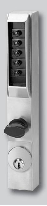
A. HARDWARE DISASSEMBLY
- A-1 Remove Adams-Rite face plate from edge of door exposing the cylinder set screws (See Figure 1) .
- A-2 Loosen the cylinder set screw (securing key cylinder to Adams-Rite latch) and remove the mortise cylinder from the dead latch assembly (See Figure 1) .
- A-3 With the exception of the Adams-Rite dead latch assembly, remove all other hardware from door: knob, handle, etc (See Figure 1) .
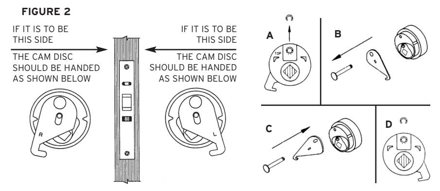
CAM PLUG HANDLING
A-4 Determine the required handing of cam disc on Adams-Rite cam plug #4580 (See Figure 2) . Looking at the edge of the door, determine on which side the lock is to be installed.
FIGURE 1 Narrow Stile Adams-Rite Dead Latch Assembly Adams-Rite Face Plate Adams-Rite Cam Plug in Cylinder Hole Part #4580 Adams-Rite Cam Plug Part #4580 (Backside) Mortise Cylinder Cylinder Set Screw
Note : Factory cam plug handing is RH.
If the cam disc handing needs to be changed, proceed with steps A to D. If not, proceed to Section B-1.
- A. Remove the retainer clip from the pivot pin.
- B. Pull the cam pivot pin out of the disc.
Note : Do not remove the driver piece.
- C. Turn the cam over and push the cam pivot pin through the cam and into the disc.
- D. Reinstall the retainer clip onto the cam pivot pin.
B. STILE PREPARATION FOR COMBINATION SIDE OF DOOR
- B-1 Install Adams-Rite cam plug #4580 to the Adams-Rite dead latch. Snug tighten the cylinder set screw (See Figure 1) . See Section E-1 for final screw adjustment .
- B-2 Position the cardboard template (locate on cam plug pins) as shown (See Figure 3) . Align template such that it is parallel to the stile of the door.
Note : It may be necessary to further loosen the cylinder set screw referred to in Section A-2 allowing movement of the template. Secure template to the stile using tape.
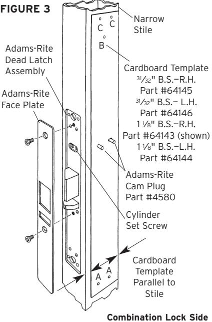
- B-3 Center punch templates holes marked A, B and C (See Figure 3) .
- B-4 Carefully remove cardboard template (to be used again in Section C-1). Drill pilot holes marked A, B and C using a .094 (3⁄32") diameter drill bit (See Figure 4) .
Note : Drill through lock side of door only. (Wear safety goggles when drilling.)
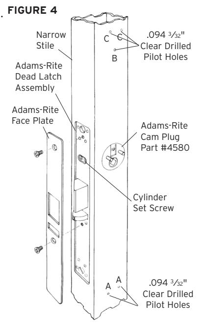
Combination Lock Side
C. STILE PREPARATION FOR TRIM PLATE SIDE OF DOOR
(Trim plate assembly is included in lock housing box marked 3001 or 3002).
C-1 Secure an Adams-Rite cam plug #4580 to the trim plate side of the dead latch assembly.
Note : Installation of this cam plug will require the opposite handing as used on the combination lock side of the door. In the event opposite handing is required, reverse cams as detailed in Section A.
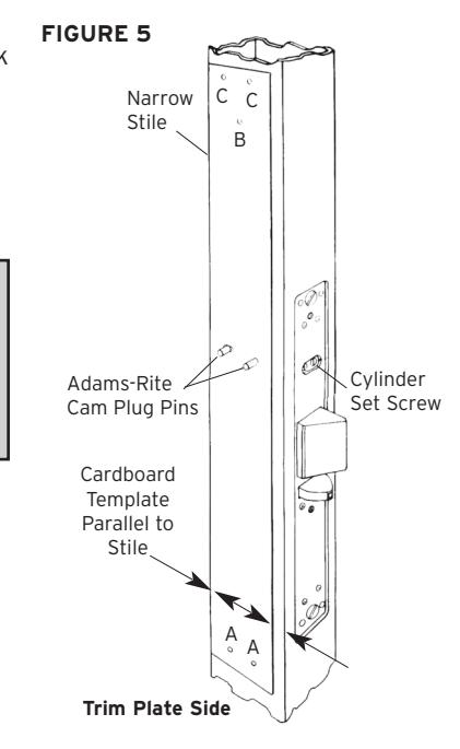
- C-2 Align and center punch holes using the cardboard template as done in Sections B-2 and B-3 on the combination lock side. Position the cardboard template as shown (See Figure 5) . (Make sure the inside trim plate imprint of template is exposed.) Center punch A, B and C holes. If obstructing hardware exists, cut cardboard template to allow for flush seating against stile.
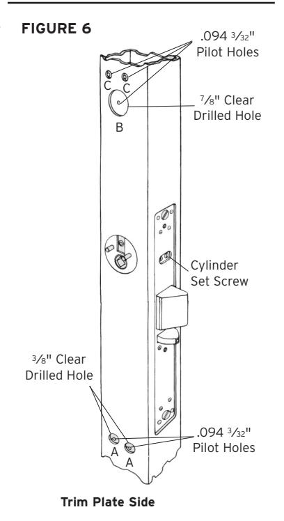
- C-3 Remove cardboard template. Drill pilot holes marked A, B and C using a .094 (3⁄32") diameter drill bit (See Figure 6) .
KABA SIMPLEX® LIMITED WARRANTY
Kaba Access Control warrants this product to be free from defects in material and workmanship under normal use and service for a period of one (1) year. Kaba Access Control will repair or replace, at our discretion, locks found by Kaba Access Control analysis to be defective during this period. Our only liability, whether in tort or in contract, under this warranty is to repair or replace products that are returned to Kaba Access Control within the one (1) year warranty period.
This warranty is in lieu of and not in addition to any other warranty or condition, express or implied, including without limitation merchantability, fitness for purpose or absence of latent defects.
ATTENTION: This warranty does not cover problems arising out of improper installation, neglect or misuse. All warranties implied or written will be null and void if the lock is not installed properly and /or if any supplied component part is substituted with a foreign part. If the lock is used with a wall bumper, the warranty is null and void. If a doorstop is required, we recommend the use of a floor secured stop.
The environment and conditions of use determine the life of finishes on Kaba Access Control products. Finishes on Kaba Access Control products are subject to change due to wear and environmental corrosion. Kaba Access Control cannot be held responsible for the deterioration of finishes.
Authorization to Return Goods
Returned merchandise will not be accepted without prior approval. Approvals and Returned Goods Authorization Numbers (RGA Numbers) are available through our Customer Service department in Winston-Salem, NC 800.849.8324. The serial number of a lock is required to obtain this RGA Number . The issuance of an RGA does not imply that a credit or replacement will be issued.
The RGA number must be included on the address label when material is returned to the factory. All component parts including latches and strikes (even if not inoperative) must be included in the package with return. All merchandise must be returned prepaid and properly packaged to the address indicated.

NO POSTAGE NECESSARY IF MAILED IN THE UNITED STATES

BUSINESS REPLY MAIL FIRST-CLASS MAIL PERMIT NO. 1563 WINSTON-SALEM, NC
POSTAGE WILL BE PAID BY ADDRESSEE
KABA ACCESS CONTROL 2941 INDIANA AVENUE WINSTON-SALEM, NC 27199-3770
REGISTRATION CARD
This lock will be used in what type of
❏
❏
❏
Hospital/Healthcare
❏ Other
(please
specify)
College/University
❏
Government/Military
❏
School/Educational
Commercial
Building
❏
Industrial/Manufacturing
❏
Airport
facility?
Thank you for purchasing our product. In order to protect your investment and to enable us to better serve you in the future, please fill out this registration card and return it to Kaba Access Control, or register online at www.kabaaccess.com
|
re
gi st er on lin e at w w w. ka ba ac ce ss .c om |
W
ha t ar ea is be in g se cu re d wi th th is loc k? (e. g. Fro nt Do or , Co |
m
m on Do or , Ex er cis e Ro om ) |
|---|---|---|
|
Na
m e |
Th
is loc k is: |
|
|
Po
sit ion |
❏
Ne w Ins ta lla tio n |
|
|
❏
Re pla cin g a co nv en tio na l ke ye d loc k |
||
|
Co
m pa ny |
❏
Re pla cin g a Ka ba Me ch an ica l Pu sh bu tto n Lo ck |
|
|
Ad
dr es s |
❏
Re pla cin g a Ka ba Ele ct ro nic Ac ce ss Co nt ro l |
|
|
Ci
ty |
❏
Re pla cin g a Ke yle ss Lo ck ot he r th an Ka ba |
|
|
St
at e ZI P (P os ta l Co de ) Co un try |
❏
Ho w Ad di d rti yo u lea rn t ab ❏ ou t Pr Ka iou ba Ac Us ce ss Co ❏ nt ro Int l Pu sh t/W bu eb tt on Lo |
❏
ck s? An ot he Us |
|
Ph
on e |
❏
Lo ck ve sm se ith m en ❏ Ma ev int en s an ce e ❏ Tr ain er ne ing Cl as s |
❏
Ot he r (p r lea se e sp ec ify ) |
|
Em
ail |
W
ha t wa s yo ur re as on fo r bu yi ng th is loc k? |
|
|
Na
m e of De ale r Pu rc ha se d Fro m |
||
|
Da
te of Pu rc ha se |
W
ho in st al led yo ur loc k? |
|
|
Lo
ck Mo de l Nu m be r |
❏
Lo ck sm ith ❏ Ma int en an ce |
❏
Ot he r |
|
❏
Ch ec k he re if yo u wo ul d lik e m or e inf or m at ion on Ka ba Ac ce |
ss
Co nt ro l loc ks |
| Notes | ||
|---|---|---|
D. DRILL LOCK AND TRIM PLATE MOUNTING HOLES
D-1 Remove Adams-Rite cam plug(s) and Adams-Rite dead latch assembly from door (See Figure 7) . (This will prevent chips from entering the latch.)
D-2 You are now ready to enlarge pilot holes marked A, B and C on both sides of stile. Enlarge holes to sizes as follows: (See Figure 8) . Enlarge 2 holes marked A to a .375 diameter (3⁄8") drill bit. Enlarge the 2 holes marked C to a .250 diameter (1 ⁄4") drill bit. Enlarge 1 hole marked B to a .875 (7⁄8") drill bit. Make sure that all holes are deburred prior to hardware assembly.
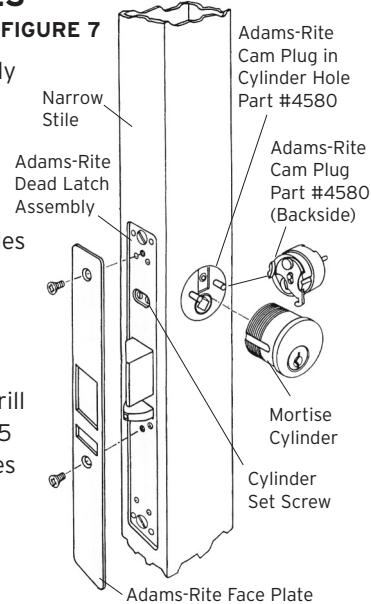
FIGURE 8 A A C C B ⁄4" Clear Drilled Hole 7⁄8" Clear Drilled Hole 3⁄8" Clear Drilled Hole Cylinder Set Screw
Trim Plate Side
E. HARDWARE ASSEMBLY
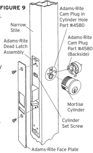
- E-1 Re-install Adams-Rite dead latch assembly. Re-install Adams-Rite cam plug or plugs (Do not tighten cylinder set screw) (See Figure 9) .
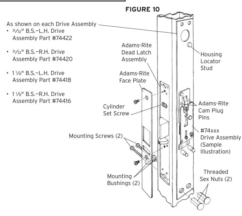
- E-2 Locate the drive assembly on lock side of door over the pins on the Adams-Rite cam plug. Secure lower portion of drive assembly using two threaded sex bolts, two mounting bushings and two 10-24 thd. X 1 3⁄4" mounting screws (See Figure 10) . Tighten the cylinder set screw. Make sure the drive moves freely up and down when holding Adams-Rite latch depressed. Drive should return freely to original position without the help of the Adams-Rite latch spring.
Note : For 31⁄32" backset, a cam plug cover is provided for covering the partially exposed cylinder hole in the stile. Place cover over cam plug pins before assembling drive assembly.
Combination Lock Side
Combination Lock Side

Kaba Access Control
2941 Indiana Avenue Winston-Salem, NC 27105 USA Tel: 800.849.8324 or 336.725.1331 Fax: 800.346.9640 or 336.725.3269