Securitron WSS Motion Sensors Installation Instructions
Open the original PDF document
View PDF

Phoenix, AZ
Tel: 1.800.624.5625
Mon-Fri: 6:00am - 4:00pm PDT
Fax: 1.800.232.7329
www.securitron.com
techsupport@securitron.com
WSS Wave Sense™ Switch
Installation Instructions
Package Contents
- Microwave motion sensor
- Faceplate Weather-resistant gasket
-
Faceplate screws Mounting ring Instructions
- Adapter ring (double-gang model only)
| Specifications | |
|---|---|
| ELECTRICAL |
INPUT 12
to 24 VAC ±10% |
|
12
to 24 VDC +30%/-10% |
|
|
50
to 60 Hz |
|
| <1.5W | |
| OUTPUT |
Relay
with switch-over contact (voltage free) |
|
Relay
contact rating (max voltage) |
60
VDC/125 VAC |
|
Relay
contact rating (max current) |
1A
(resistive) |
|
Max
switching power |
30W
(DC)/60 VA (AC) |
|
DETECTION
RANGE |
4" to 24" (10cm to 60cm)(adjustable) |
|
DETECTION
MODE |
Motion
(bidirectional) |
|
OUTPUT HOLD
TIME |
0.5s
(in pulsed mode) |
|
OPERATING
TEMPERATURE |
-4
°F to +131 °F (-20 °C to +55 °C) |
| IMMUNITY |
Immune
to electrical and radio frequency interference |
| WEIGHT |
0.34
lbs (0.15 kg) |
| REGULATORY |
Electromagnetic
compatibility (EMC) according to 2004/108/EC FCC: G9B-MS08 IC: 4680A-MS08 |
Precautions
- 1. SHUT OFF power to power source before attempting any wiring procedures.
- 2. MAINTAIN a clean and safe environment when working in public areas.
- 3. Constantly BE AWARE of pedestrian traffic around the door area.
- 4. Always STOP pedestrian traffic through the doorway when performing tests that may result in unexpected reactions by the door.
- 5. OBSERVE proper protocols for circuit board handling to protect the unit from electrostatic discharge.
- 6. Before handling any board, ENSURE dissipation of any bodily charge.
- 7. CHECK placement of all wiring before powering to ensure that moving door parts do not catch wires and cause damage to equipment.
- 8. ENSURE compliance with all applicable safety standards (i.e., ANSI A156.10/A156.19) upon completion of installation.
- 9. DO NOT ATTEMPT any repair of the sensor.
-
10. AVOID the following concerning unauthorized disassembly or repair:
- It may jeopardize personal safety and may cause exposure to the risk of electrical shock.
- It will void the product warranty.
Installation / Wiring / Setup
Installation
- 1. MOUNT the WSS using the included mounting ring or in a standard plastic or metal electrical gang box, as applicable, and depending on the type of door installation.
- NOTE 1: The weather resistant foam is used as a protective barrier against the elements.
- NOTE 2: The plastic adapter ring enables the double gang face plate to attach to various plastic and metal gang boxes.
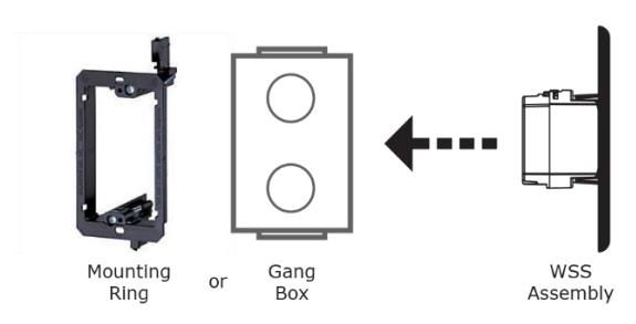
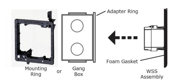
- 2. DO NOT ALLOW contact between the sensor and a metal gang box to prevent shorting the devices.
- 3. ENSURE placement of the device so that motion from the door or other types of movement do not interfere with the detection zone.
Wiring
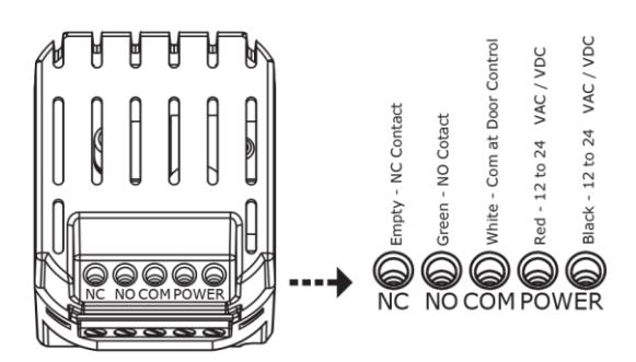
1. WIRE the four-conductor cable as shown below.
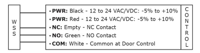
2. ATTACH the four-conductor cable connector to the WSS as shown below.
Setup
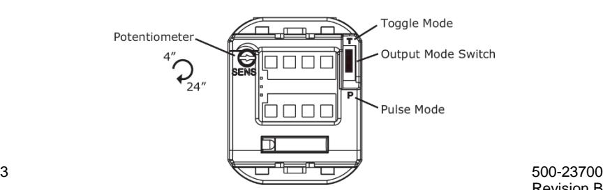
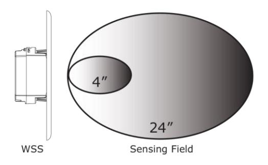
NOTE: Two adjustments can be made to the sensor. The Potentiometer adjusts the size of the unit's sensing field, and the Output Mode Switch selects Toggle or Pulse Mode.
1. ADJUST unit to desired setup (see figures below).
NOTE: Sensing field may be adjusted from 4" to 24".
- a. ROTATE the potentiometer to increase the sensing field.
- NOTE 1: Toggle Mode is recommended for switch applications. In Toggle Mode, a detection activates the relay and a second detection
deactivates the relay.
- NOTE 2: Pulse Mode is recommended for automatic door applications. In Pulse Mode, a detection activates the relay for a short period of time, depending on the duration of movement in front of the door.
- b. ADJUST the Output Mode by moving the Output Mode Switch to the up position (Toggle Mode) or down position (Pulse Mode).
Troubleshooting
PROBLEM: Door does not open when swiping hand in front of sensor.
CAUSE/ACTION: 1. Bad or no power supply. . CHECK power supply. If LED switches on or flashes, power connections are OK.
2. Detection range is too small. ADJUST the detection range. REMOVE
any metal plates in front of sensor.
3. Wrong connection. CHECK wiring and relay connection.
PROBLEM: Door remains permanently open.
CAUSE/ACTION: 1. Environmental conditions are influencing the sensor. REMOVE any
moving objects close to the sensor.
2. Wrong connection. CHECK wiring and relay.
PROBLEM: The door remains open after detection/activation.
CAUSE/ACTION: 1. Wrong output mode. SWITCH the output mode to Pulse Mode.
2. Wrong connection. CHECK wiring and relay connection.
FCC Approval
This device complies with Part 15 of the FCC Rules and with RSS-210 of Industry Canada.
Operation is subject to the following two conditions:
- 1. This device may not cause harmful interference, and
- 2. This device must accept any interference received, including interference that may cause undesired operation.
IMPORTANT NOTE
Changes or modifications to this equipment that are not expressly approved may void the FCC authorization to operate this equipment.