Securitron UHB, UHB-82 Brackets Installation Instructions
Open the original PDF document
View PDF

SECURITRON MODEL UHB, UHB-82 UNIVERSAL HEADER BRACKET INSTALLATION INSTRUCTIONS
1. DESCRIPTION
The model UHB bracket is used with the model 62 or model 32 Magnalock for installations where the door header is not wide enough to accommodate the magnet (commonly the case with aluminum frame glass doors). A longer version (UHB-82) is used with the model 82 Magnalock. The bracket can be mounted in either of two orientations to yield the strongest and most attractive installation. It also allows concealment of the Magnalock wire cable which contributes to security and appearance. Finally, the bracket has a 2nd use as a splice chamber which can mount electronic accessories as explained in Section 3. U.S. and metric (UHBM) versions are available as are two finishes: CL (clear aluminum) and BK (black aluminum).
2. MOUNTING
Note that the bracket can be positioned vertically or horizontally to yield a 1" or 1 1/2" (25 or 58MM) extension to the header. The choice depends on how far the header needs to be extended to fit the magnet. Extending the header only 1" (vertical position of bracket) yields a stronger installation and so we recommend this unless a greater extension is required.
Refer to Figure 4 of the Magnalock instructions for a view showing the positioning of the bracket. Note that the stop filler plate is usually not required. Many aluminum frame glass doors have no stops and in other cases, the stop is a "blade" type which can be cut away.
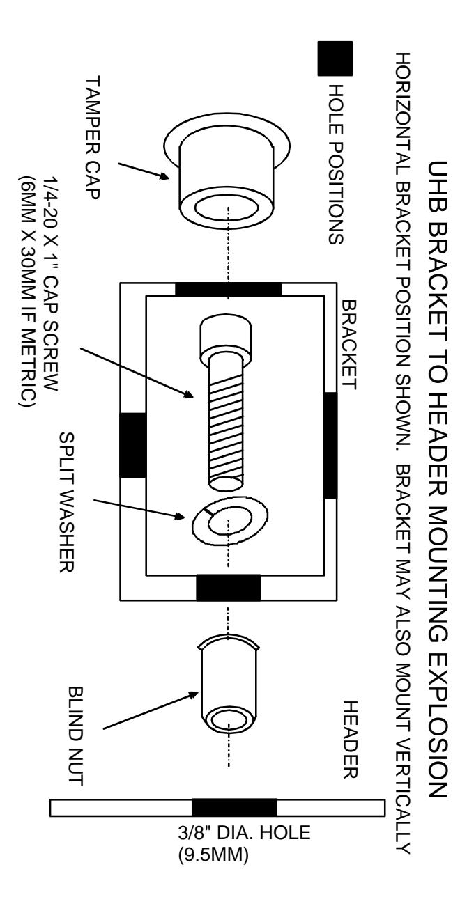
Generally the first installation step is to drill a hole in the header for wire pulling and then drill a matching hole in the bracket. You then mount the bracket to the header following the drawing shown on Page 2. The blind nuts are collapsed with either the tool packed with Magnalocks or with Securitron's blind nut collapsing tool (part of the Magnalock installation tool kit).
With the bracket mounted, the magnet can now be mounted to the header and bracket following the template and Magnalock instructions. For the model 62 or 82, the magnet front screws will ideally enter the header directly and the rear screws will enter the bracket with the cable also entering the bracket. Two other possibilities exist. All four screws may enter the bracket if the header is quite narrow, or the Magnalock front screws may fall on the intersection of the bracket and the header. In the latter case, it is acceptable to use only the back mounting screws on aluminum frame glass doors. On such doors, however, the close point can be adjusted to allow use of all 4 screws unless there is a dead lock which will still be in use. Note that we supply two shorter (2 1/2" or 60MM) magnet mounting screws with the bracket hardware pack. If these screws are used for magnet to bracket mounting, they block the bracket interior less than the 3" (75MM) screws supplied with the Magnalock which makes wire splicing easier. The model 32 has only two magnet mounting screws so its case is simpler than the one described above.
Note that the bracket is longer than the magnet which provides installation flexibility. The final step after all screws are secure is to tap in the tamper caps. Note that the caps go in with difficulty which makes them more secure. We advise driving them in gently with numerous hammer taps so as to avoid the possibility of bending the bracket. The large rectangular caps which seal the end of the bracket are best driven in with two hammers striking both ends of the bracket at the same time. This avoids pressuring the mounting screws by hitting one side at a time. You'll find that if the magnet is centered on the bracket, both rectangular end caps go in cleanly. If, however, you've chosen to offset the magnet on the bracket, the magnet mounting screw will interfere with the end cap. To deal with this, cut away part of the inside of the end cap with a nipper to clear the mounting screw.
3. USE AS SPLICE CHAMBER
The empty space inside the bracket can be put to use to mount certain electronic accessories. Examples include LED's, alarm sounders, relays and timers. LED's may be used to annunciate the status of the lock or of an alarm system. A good use for an alarm sounder is to arrange for it to sound when the lock has been released from the inside to admit someone. The sounder can be driven by an SPDT external switch which is releasing the Magnalock or a relay can be placed within the bracket to supply contacts to operate the sounder when the lock has been released. Finally, a timer is often required to release the Magnalock for a certain period when a switch has been momentarily depressed. Securitron's model TM-8 TimeMate timer has been designed to fit within the UHB bracket if it cannot be mounted with the switch.
.50 1.87 1.87 2.25 2.5 2.5 2.25 9.5 1.06 .53 HORIZONTAL EDGE COMBINED TEMPLATE FOR BRACKET .78 .78
1.56
SERVES AS ITS OWN TEMPLATE. NOTE: MODEL UHB-82 FOR MODEL 82 MAGNALOCK FOR BLIND NUTS. DIMENSIONS SHOWN IN INCHES. HOLES SHOULD BE 3/8" (9.5 MM) DIAMETER OR VERTICAL (2 HOLES, BOLD) POSITION IN HORIZONTAL (3 HOLES, DOTTED))