Securitron TJ-38, TJ-68 Installation Instructions
Open the original PDF document
View PDF

INSTALLATION INSTRUCTIONS FOR TJ-38 & 68 TOP JAM KIT Inswinging Door Configuration Lock Mount Kit For Model M38 and M68 Magnalocks
1. DESCRIPTION
Securitron's TJ-38 & 68 Top Jam Kits are bracket accessory kits that provide the necessary hardware required for the inswinging door mount configuration for the Model M38 or M68 Magnalocks. Each kit is used to mount either an M38 or M68 on the secure side of a door that swings into a secured area. The kit includes a TJ-Bracket to mount the lock at or above the door frame (header), a Z-Bracket for mounting the strike to the door, and a Dress Cover to conceal the assembly and provide an attractive finished appearance.
2. PRODUCT OVERVIEW
Upon unpacking, an inventory should be made to ensure that all the required components and hardware have been included. Along with these instructions, the Top Jam Kit package should contain the following items:
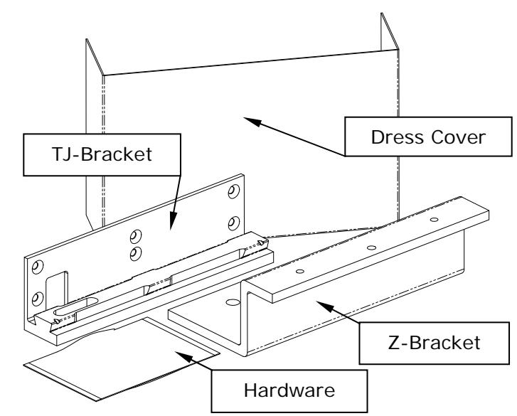
This manual will address in detail the installation of an M38 or M68 on an inswinging door using the TJ-38 or TJ-68 Top Jam Kit. The following illustration shows the basic mounting arrangement (TJ-38 shown):
INCLUDED HARDWARE:
| 6X | Item #1 | 6X | Item #2 | 6X | Item #3 |
|---|---|---|---|---|---|
| Phillips Flat Head | Phillips Flat Head | Phillips Flat Head | |||
| #12 X 1-1/2" Type "A" | #14 X 4" Type "A" | 1/4-20 X 1-1/2" | |||
| 6X | Item #4 | 2X | Item #5 | 1X | Item #6 |
|---|---|---|---|---|---|
|
Blind Nut
1/4-20 |
Slotted Hex Head
#14 X 1-1/4" Type "A" |
Socket Head Cap
5/16-18 X 1-1/2" |
|||
| 1X | Item #7 | 1X | Item #8 | 1X | Item #9 |
|---|---|---|---|---|---|
| Socket Flat Head | Washer, Neoprene, 1/8" Thick | T-Nut | |||
| 5/16-18 X 1" | 1" O.D. X 11/32" I.D | 5/16-18 | |||
| 2X | Item #10 | 2X | Item #11 | |
|---|---|---|---|---|
| Roll Pin | Roll Pin | |||
| 1/4" Diameter X 3/4" | 1/4" Diameter X 1" | |||
This kit provides only the brackets and additional hardware that are required to install a single M38 or M68 unit in the inswinging door mounting configuration. These instructions make reference to existing hardware that is included with the original Magnalock product package. Please refer to the Installation and Operating Instructions provided with the lock for additional installation information and lists of originally furnished parts.
3. RECOMMENDED TOOLS
Hammer Wrench, 1/2" box-end
Center punch Pliers, vise grip
Drill motor Screwdrivers: #1 and #3 Phillips
Drill bits: 3/16", 7/32" 3/8" and 1/2" Hex (Allen) wrenches: 1/16", 3/16" and 1/4"
4. GENERAL INSTALLATION INFORMATION
As with any product installation the proposed mounting area and structure should be evaluated and the task should be thoroughly planned before drilling any holes.
Lock and Strike Installation using Top Jam Kit:
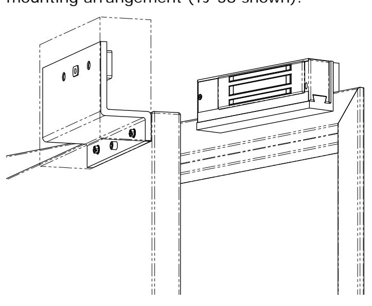
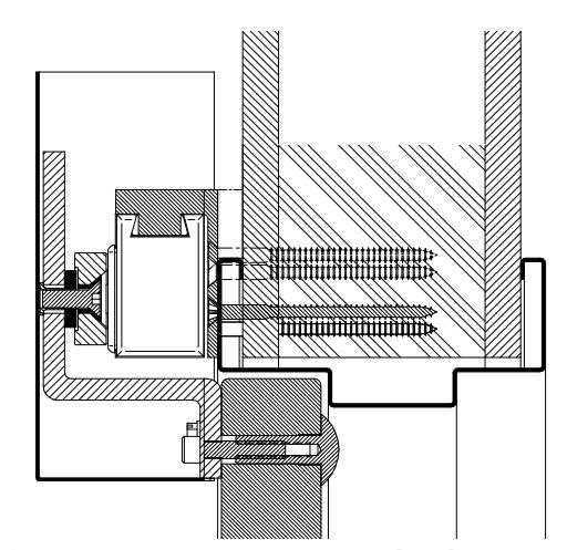
The first step in installing the lock in this configuration is to identify the desired location for the lock housing (magnet). The TJ-Bracket may be mounted so that the lock is inverted from the standard mount as shown in Figure 1 , or may be upturned so that the lock is suspended by the bracket from the top as shown in Figure 2 .
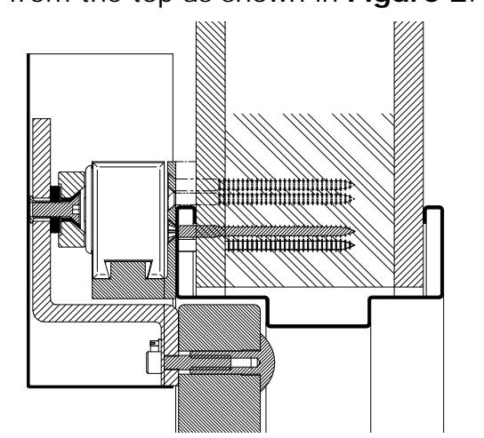
Figure 1 - Mount Interlock at Bottom Figure 2 - Mount Interlock at Top
The TJ-Bracket has six (6) mounting holes that can be used, and hardware has been included with the kit to anchor the bracket to a variety of structural mounting surfaces. Figure 3 below is a cross section view of a typical M38 Magnalock installation on a metal door frame in the inswinging door mount configuration using the TJ-38 Kit:
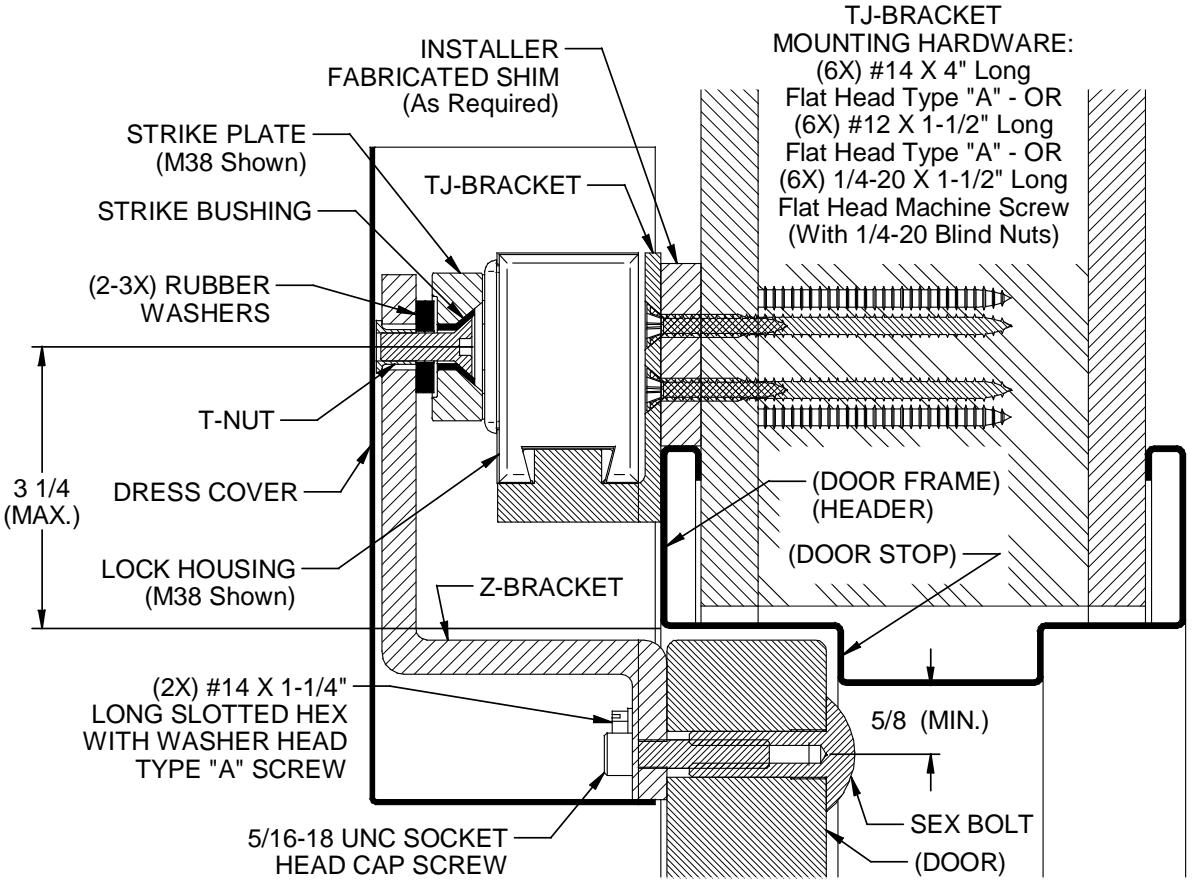
Figure 3
Notes for TJ and Z-Bracket locations:
- 1) When positioning the lock assembly, the center of the magnet must be located within the 3- 1/4" area from the edge of the door opening. This will provide adequate room for the strike mounting hardware on the Z-Bracket. (See Figure 3 ).
- 2) The Z-Bracket is the same width as that of the lock/TJ-Bracket assembly on the door frame. This relationship (width edge-to-edge alignment) must be maintained for proper installation.
- 3) Prior to drilling holes in the door, double-check to confirm that there is adequate space to drill the three (3) holes required in the long leg of the Z-Bracket for the strike mounting. (At this point the Z-Bracket may also be used as a template to mark the three (3) mounting hole locations for drilling the door).
5. LOCK INSTALLATION
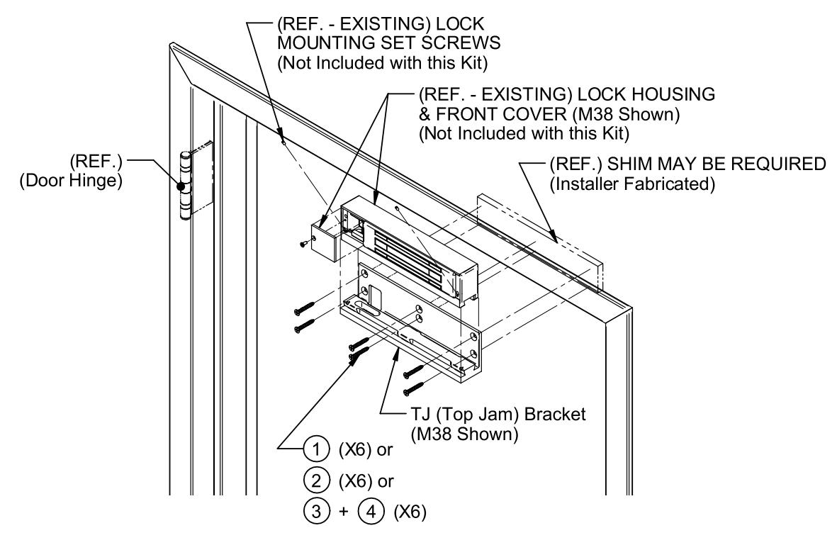
Figure 4
After establishing the position for the mounting of the lock/TJ-Bracket, use Figure 4 above and the following step-by-step installation sequence to mount the lock onto the door frame/header. (The TJ-Bracket may be used as a template to mark the required mounting hole locations).
After marking the desired mounting holes on the door frame mounting surface, center punch these locations, and then:
For Metal Door Frame/Header: Drill 3/8" [9.5mm] diameter holes through the door frame at each location and install blind nuts ( Item #4 ) into the 3/8" [9.5mm] diameter holes in the door frame as follows:
- a. Using the blind nut collapsing tool provided (with blind nut in place), insert the end of the blind nut into the hole.
- b. Using a hammer (if necessary) tap the nut in until the upper lip seats against the door frame surface.
- c. While holding the hex portion of the collapsing tool with a 1/2" box-end wrench or vise grip pliers, turn the socket head cap screw of the tool using a 3/16" hex wrench. Note: Maintain firm pressure toward the door frame mounting surface while collapsing the nut.
- d. Once the blind nut is adequately collapsed, remove the tool from the nut by backing the cap screw out of the blind nut thread.
- e. Install each successive blind nut onto the collapsing tool (cap screw) and repeat steps a through d above until all desired blind nuts have been installed.
For Wood Door Frame/Header:
If using #12 X 1-1/2" long screws (Item #1): Drill 3/16" [4.8mm] diameter holes X 1-1/4" [31.8mm] deep (minimum) into the door frame at each of these locations.
If using #14 X 4" long screws (Item #2): Drill 7/32" [5.5mm] diameter holes X 3-3/4" [95.3mm] deep (minimum) into the door frame at each of these locations.
-
Place the TJ-Bracket onto the frame mounting surface aligning the holes in the bracket with the previously installed blind nuts (for metal frame) or drilled holes (for wood frame). Using a #3 Phillips screwdriver, secure the bracket to the frame with:
- For Metal Door Frame/Header: Use 1/4-20 X 1-1/2" long Phillips flat head screws ( Item #3 ) provided.
- For Wood Door Frame/Header: Use #12 X 1-1/2" long Phillips flat head type "A" screws ( Item #1 ) or #14 X 4" long Phillips flat head type "A" screws ( Item #2 ) provided.
- Establish location then drill a 3/8" [9.5mm] diameter hole through the door frame for the lock power cable. Note: This hole must be positioned within the large slotted "window" in the back of the TJ-Bracket when the bracket is installed on the frame mounting surface.
-
Remove the standard mounting bracket (originally included with the lock) from the top of the lock housing as follows:
- a. Using a #1 Phillips screwdriver, remove the 8-32 flat head screw holding the lock housing front cover in place. Remove cover and set aside the screw and cover for later assembly.
- b. Using a 1/16" hex wrench, back the two (2) 6-32 socket set screws out far enough to disengage the mounting bracket. Note: It is not necessary to completely remove the set screws – five (5) 360-degree counterclockwise turns is normally far enough.
- c. Slide the bracket to disengage from the top of the lock housing. Note: The bracket/lock interface can be disengaged by sliding the lock (or bracket) 1" to 2" laterally to one side or the other, then withdrawing away vertically – sliding the lock or bracket the full length of the housing to remove or install is not necessary.
- Assemble the lock housing to the TJ-Bracket by engaging the top of the lock with the bracket and sliding the lock into position (centered on the bracket). Tighten the two (2) 6-32 socket set screws using a 1/16" hex wrench to secure the assembly.
- After all electrical wiring has been completed, install the housing front cover and fasten in place using the 8-32 flat head screw (previously removed).
6. STRIKE INSTALLATION
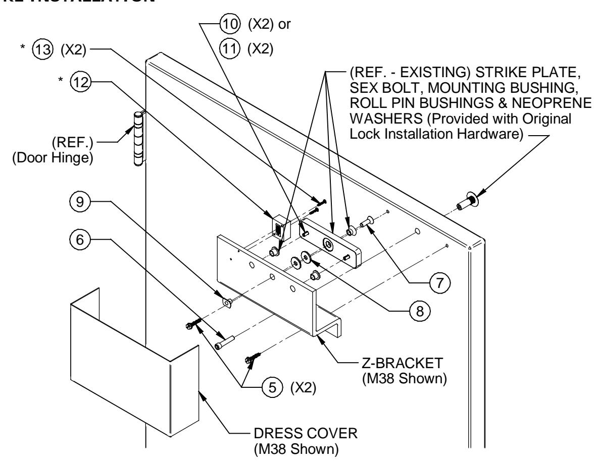
Figure 5
*Note: Items #12 and #13 are not included with this kit. They are shown here for reference when installing a "D" (Door Position) version lock using the TJ-bracket. See the Door Position Actuator Installation section of this manual and the installation template furnished with the lock for detailed mounting information.
After the mounting of the lock/TJ-bracket has been completed, use Figure 5 and the following step-by-step installation sequence to complete the mounting of the Z-Bracket and strike assembly to the door:
- After marking the Z-Bracket mounting holes on the door, center punch these locations.
- Drill one (1) 3/8" [9.5mm] diameter hole through door at the Z-Bracket center hole mark, then drill 1/2" [12.7mm] diameter X 1-1/2" [38.1mm] deep through door from opposite side for the sex bolt.
- From the side of the door that the Z-Bracket will be mounted, drill two (2) 7/32" [5.5mm] diameter X 1-3/8" [34.9mm] deep holes at each of the other two marked locations.
- Position the bracket onto the door, aligning the bracket holes to the holes drilled in the door.
- Using a flat blade screwdriver (or hex drive socket/wrench), secure the bracket to the door using the two (2) #14 X 1-1/4" long slotted hex head type "A" screws ( Item #5 ) provided, through the two holes on each side of the center hole.
- With the Z-Bracket partially installed and the door in the closed position, mark the bracket horizontally and vertically to indicate the required center hole position for mounting the strike plate.
- Using a screwdriver (or wrench), remove the Z-Bracket from the door and mark for the remaining two (2) holes for the roll pin bushings - 2.25" [57.2mm] to each side of the center hole (all holes share the same center line horizontally).
- Drill one 3/8" [9.5mm] diameter hole through the Z-Bracket at the center (strike mounting) hole.
- Drill two (2) 1/2" [12.7mm] diameter holes through the Z-Bracket at the marks to each side of the center hole.
Door Position Actuator Installation: For locks that include the "D" (Door Position) option, install the actuator block by performing the following:
- a. After marking the mounting holes for the actuator block ( Item #12 ) on the Z-Bracket using the mounting template provided with the lock (or upgrade kit), center punch these locations.
- b. Drill two (2) 1/8" [3.2mm] diameter holes through the Z-Bracket at the center punched locations.
- c. Using a #1 Phillips screwdriver secure the actuator block to the Z-Bracket with the two (2) #6 X 3/4" long Phillips pan head type "A" screws ( Item #13 ) provided. Note: Make sure that the arrow of the label on the backside of the block is facing toward the mounting edge of the lock .
If a field upgrade to the "D" version is being performed, please use the installation template (P/N 500-61050) included with the upgrade kit to install the switch inside the front cover. (See the installation and operating instruction manual included with the lock for electrical specifications of the switch).
- Reinstall the Z-Bracket to the door using the two (2) #14 X 1-1/4" long slotted hex head type "A" screws ( Item #5 ).
- Insert the 5/16-18 X 1-1/2" long socket head cap screw ( Item #6 ) through the center Z-Bracket mounting hole and into the door.
- Start the sex bolt into the 1/2" [12.7mm] diameter hole from the opposite side of the door. Do not fully seat the sex bolt against the surface of the door at this time, but thread the sex bolt onto the end of the mounting screw. Using a 1/4" hex wrench, continue to thread the mounting screw into the sex bolt while ensuring that the assembly maintains a straight (perpendicular) alignment to the door.
- Using a hammer and the 1/4" hex wrench, gradually tighten the screw into the sex bolt until it is snug, and then tap the head of the sex bolt toward the face of the door. Keep repeating this procedure to slowly "walk" the sex bolt into place (head against door face) – this ensures a straight (perpendicular) alignment of the sex bolt to the door.
- Insert the two (2) strike roll pin bushings into the 1/2" [12.7mm] diameter holes in the Z-Bracket (See Figure 5 ). Note: The roll pin bushings will need to be cut to the same thickness as the Z-Bracket. This is required so that the bushings do not extend beyond the surface of the Z-Bracket and interfere with the Dress Cover installation.
- Insert the plastic strike mounting bushing and the 5/16-18 X 1" long socket flat head screw ( Item #7 ) through the center hole of the strike.
- Install two (2) of the neoprene washers ( Item #8 ) over the screw on the opposite side (roll pin hole side) of the strike.
- Holding the T-Nut ( Item #9 ) into the center hole on the back side of the Z-Bracket, position the strike to the front side of the bracket. Insert and thread the 5/16-18 socket flat head screw ( Item #7 ) into the T-Nut.
- Using a 3/16" hex wrench, lightly tighten the assembly to snug.
- Verify proper spacing relationship between face of lock (magnet) and strike plate. The face of the strike should contact the face of the lock when the door is closed. Note: A total of four (4) washers ( Item #8 ) are provided (between the original lock hardware pack and the one in this kit). Note: Usually 2-3 washers are adequate to provide correct spacing, and washers may be added or removed as necessary to create proper fit, but at least one (1) washer must be installed between the strike and Z-Bracket.
PN# 500-19900 Page 6 Rev. F, 04/11
- After proper strike spacing has been established, determine the correct roll pins to use. If 1- 2 washers are utilized, use the 3/4" [19.1mm] long roll pins ( Item #10 ). For 3-4 washers, use the 1" long roll pins ( Item #11 ).
- Remove the strike plate from the Z-Bracket and place on a clean, flat surface. Using a hammer, insert and lightly tap to install the two (2) roll pins ( Item #10 or #11 ) into the two (2) 1/4" [6.4mm] diameter recesses of the strike. Note: Care should be taken when installing roll pins into the strike. Excessive impact to the strike or over-driving the pins into the recesses may distort the contact surface of the strike which will affect the holding force of the lock.
- Install the strike inserting the screw into the Z-Bracket T-Nut and aligning the roll pins into the bushings. Using a 3/16" hex wrench, tighten the 5/16-18 flat head screw into the T-Nut until it is snug. Note: Do not over tighten. When the strike is fully installed there should be some play or flexing of the strike around the washers. This allows the lock to pull the strike into the correct alignment for maximum holding force.
Dress Cover Installation: After all adjustments to the bracket installation have been completed, install the dress cover as follows:
- a. Using a clean cloth and a household cleaner, wipe off the back of the Z-Bracket and allow it to dry.
- b. Remove the backing from the two (2) strips of tape on the inside of the cover.
- c. With the door closed, vertically position the cover open-end-up to the desired location, and then visually align the cover horizontally so that there is an equal spacing of clearance to each side of the lock inside the cover.
- d. Firmly press the cover into place against the back of the Z-Bracket to secure.
IF ADDITIONAL INSTALLATION ASSISTANCE IS REQUIRED CALL SECURITRON TOLL FREE: 1-800-MAG-LOCK