Securitron SMLS, SMSS Installation Instructions
Open the original PDF document
View PDFINSTALLATION INSTRUCTIONS FOR SMLS/SMSS Surface Mount Lock Shear & Surface Mount Strike Shear
1. RECOMMENDED TOOLS
Drill Motor
Drill Bit: 3/8" [9.5mm]
Screwdrivers: Phillips and Standard Measuring Tool (ruler or tape measure)
Hex (Allen) Wrenches: 1/8" (provided in Metric Hardware Pack), 5/32" [4mm] and 3/16"
Blind Nut Installation Tool
2. INSTALLATION INSTRUCTIONS
Magnalock Installation using SMLS/SMLSM
Figure 1 below is an exploded illustration of the general SAM lock mounting configuration available using the hardware provided:
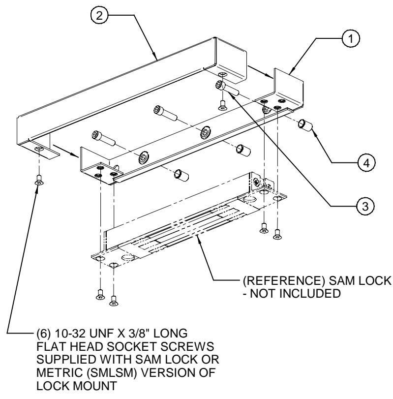
Figure 1
Note: The items represented by the phantom/dashed lines are for reference only – the SAM Magnalock and its associated hardware are NOT included with this product.
U.S. Standard:
| ITEM | QTY | DESCRIPTION | ||
|---|---|---|---|---|
| 1 | 1 | Lock/Strike Mounting Bracket | ||
| 2 | 1 | Lock/Strike Bracket Cover | ||
| 3 | 3 | 1/4-20 UNC X 1" Long Socket Head Cap Screw | ||
| 4 | 3 | 1/4-20 UNC Blind Nut, 1-Piece, Steel | ||
Metric:
| ITEM | QTY | DESCRIPTION |
|---|---|---|
| 1 | 1 | Lock/Strike Mounting Bracket |
| 2 | 1 | Lock/Strike Bracket Cover |
| 3 | 3 | M6-1.0 X 25MM Long Button Head Socket Cap Screw |
| 4 | 3 | M6-1.0 Blind Nut, 1-Piece, Steel |
| 5 | 6 | 10-32 UNF X 3/8" Long Flat Head Socket Screw |
| 6 | 1 | Hex Wrench, 1/8" |
Strike Armature Installation using SMSS/SMSSM
Figure 2 below is an exploded illustration of the general strike armature mounting configuration available using the hardware provided:
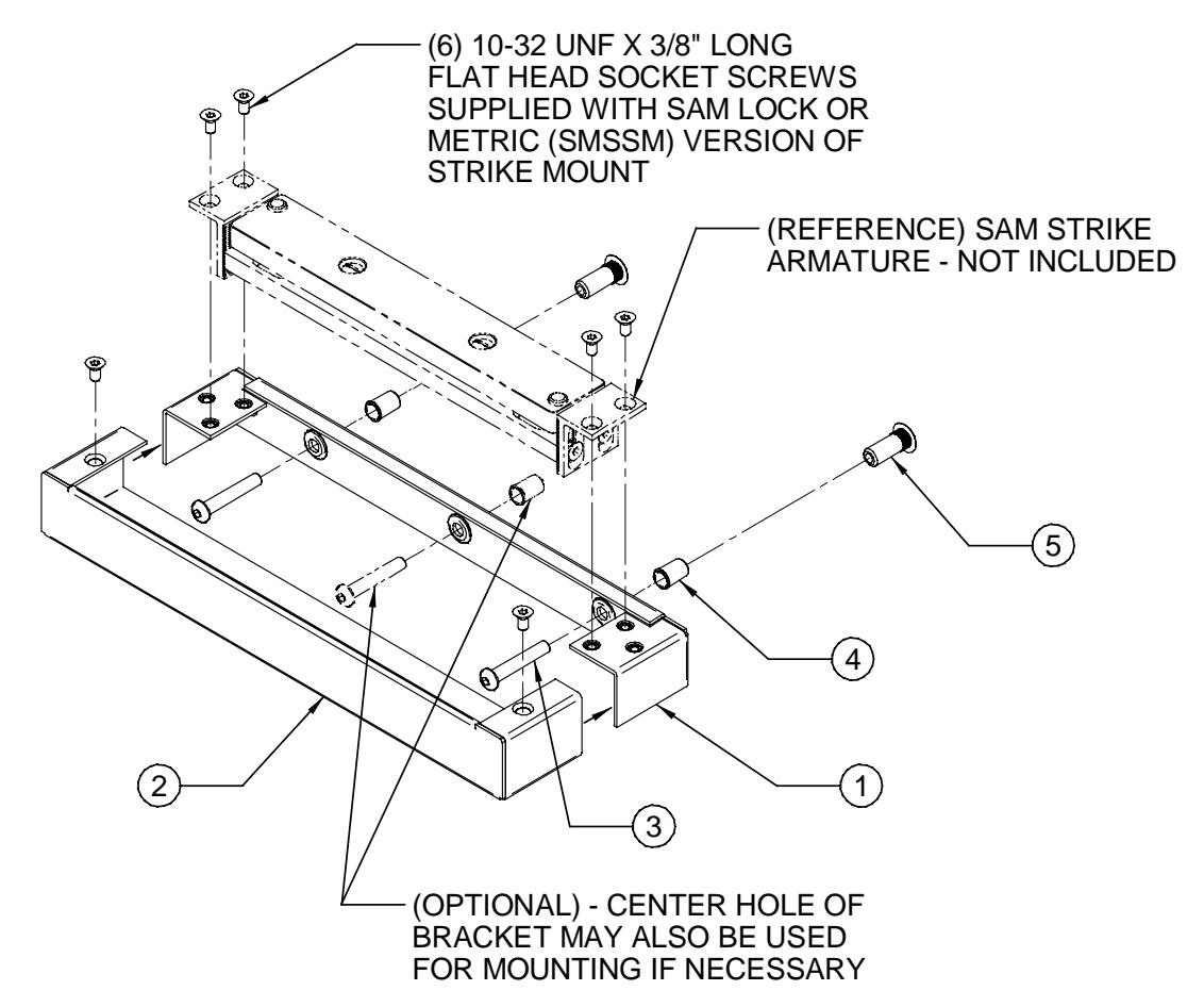
Figure 2
Note: The items represented by the phantom/dashed lines are for reference only – the SAM Strike Armature and its associated hardware are NOT included with this product.
U.S. Standard:
| ITEM | QTY | DESCRIPTION | ||
|---|---|---|---|---|
| 1 | 1 | Lock/Strike Mounting Bracket | ||
| 2 | 1 | Lock/Strike Bracket Cover | ||
| 3 | 3 | 1/4-20 UNC X 1-1/2" Long Button Head Socket Cap Screw | ||
| 4 | 2 | 1/4-20 UNC Blind Nut, 1-Piece, Steel | ||
| 5 | 2 | Sex Bolt, 1/4-20 UNC X 1" Long, Steel | ||
Metric:
| ITEM | QTY | DESCRIPTION |
|---|---|---|
| 1 | 1 | Lock/Strike Mounting Bracket |
| 2 | 1 | Lock/Strike Bracket Cover |
| 3 | 3 | M6-1.0 X 40MM Long Button Head Socket Cap Screw |
| 4 | 2 | M6-1.0 Blind Nut, 1-Piece, Steel |
| 5 | 2 | Sex Bolt, M6-1.0 X 25MM Long, Steel |
| 6 | 6 | 10-32 UNF X 3/8" Long Flat Head Socket Screw |
| 7 | 1 | Hex Wrench, 1/8" |
PN# 500-12400 Page 2 Rev. D, 03/11
SMLS (Lock) Bracket Installation
The following illustrations display installation of the SAM Magnalock body in the SMLS bracket configuration and show examples of some typical swinging door applications:
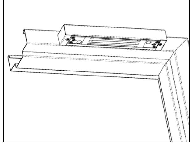

Magnalock Body:
- 1. Place the SMLS/SMLSM mounting bracket (Item #1) into position on frame at mounting location. Using the bracket as a template, mark the three (3) (dimpled) hole locations for mounting. Also select and mark one of the end hole locations for the Magnalock power cable.
- 2. Drill three (3) 3/8" [9.5mm] diameter holes into door frame mounting surface for blind nuts.
- 3. Drill one (1) 3/8" [9.5mm] diameter hole for the lock power cable through the door frame at the desired end of the bracket.
- 4. Using a blind nut installation tool, install the three (3) steel blind nuts (Item #4).
- 5. Install the bracket (Item #1) using the three (3) socket head screws (Item #3). Tighten the screws firmly using a 3/16" or 4mm hex wrench.
- 6. Orient Magnalock body into bracket, routing the power cable through the 3/8" hole, and mount lock to bracket using the hardware supplied with the lock. Tighten the screws of the assembly using a 1/8" hex wrench.
- 7. Run power cable to electrical terminal connection as required.
- 8. Slide the bracket cover (Item #2) into place over the bracket and using a 1/8" hex wrench, install the two (2) 10-32 UNF x 3/8" long flat head socket screws to secure the cover.
SMSS (Strike) Bracket Installation
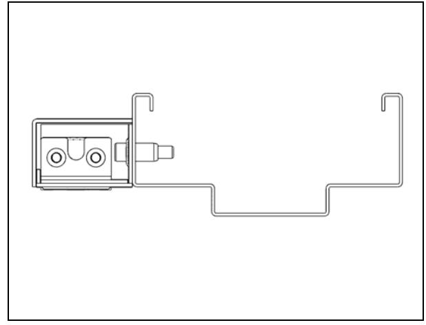
The following illustrations display installation of the SAM strike armature in the SMSS bracket configuration and show examples of some typical swinging door applications:
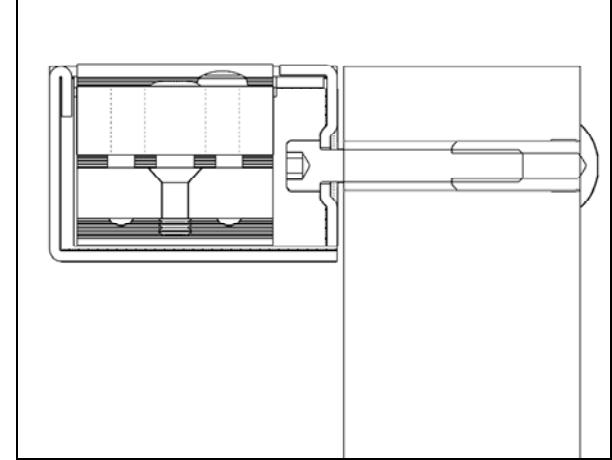
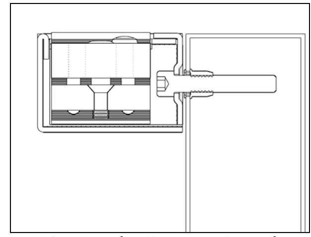
Side View (Wooden/Solid Core Door) Side View (Hollow Metal Door)
Wooden and Solid Core Door Installation
- 1. Place mounting bracket into position on door mounting location. Using the bracket as a template, mark the two (2) outside (dimpled) hole locations for mounting.
- 2. Drill two (2) 3/8" [9.5mm] diameter holes completely through the mounting surface (door).
- 3. Partially insert two (2) sex bolts (Item #5) into the holes in the door. Mount the bracket (Item #1) securely into place threading the socket head screws (Item #3) into the sex bolts (Item #5). While tapping the sex bolts into place with a hammer, tighten the screws into the sex bolts using a hex wrench. Verify proper alignment.
PN# 500-12400 Page 3 Rev. D, 03/11
- 4. Orient strike armature assembly into bracket and mount the assembly to the bracket using the hardware supplied with the strike. Tighten the screws of the assembly using a 1/8" hex wrench.
- 5. Slide the bracket cover (Item #2) into place over the bracket and using a 1/8" hex wrench, install the two (2) 10-32 UNF x 3/8" long flat head socket screws to secure the cover.
Aluminum Frame and Hollow Metal Door Installation
Note: For installation on hollow metal or aluminum frame doors, mounting with sex bolts (Item #5) or blind nuts (Item #4) is optional. If using sex bolts the two (2) outside (dimpled) holes of the bracket will be used and 3/8" diameter holes that penetrate completely through the door will be required. If using blind nuts, all three (3) holes of the bracket will be used and 3/8" diameter holes that penetrate only through the mounting face or skin of the door will be necessary.
- 1. Place mounting bracket into position on door mounting location. Using the bracket as a template, mark the desired holes required for mounting.
-
2. Drill holes in the mounting surface (door):
- a) For sex bolt mounting ; drill two (2) 3/8" [9.5mm] diameter holes completely through the mounting surface (door).
- b) For blind nuts mounting ; drill three (3) 3/8" [9.5mm] diameter holes through the mounting face (skin) of the door only.
-
3. Insert hardware into holes in door:
- a) For sex bolt mounting ; partially insert two (2) sex bolts (Item #5) into the holes in the door. Mount the bracket securely into place threading the socket head screws (Item #3) into the sex bolts (Item #5). While tapping the sex bolts into place with a hammer, tighten the screws into the sex bolts using a hex wrench. Verify proper alignment.
- b) For blind nuts mounting ; Using a blind nut installation tool, install the three (3) steel blind nuts (Item #4) into the mounting face (skin) of the door. Position and mount the bracket (Item #1) securely into place threading the socket head screws (Item #3) into the blind nuts (Item #4).
- 4. Orient strike armature assembly into bracket and mount the assembly to the bracket using the existing hardware supplied with the strike. Tighten the screws of the assembly using a 1/8" hex wrench.
- 5. Slide the bracket cover (Item #2) into place over the bracket and using a 1/8" hex wrench, install the two (2) 10-32 UNF x 3/8" long flat head socket screws to secure the cover.
3. MAGNACARE ® LIFETIME REPLACEMENT WARRANTY
For warranty information visit: www.securitron.com/en/site/securitron/About/MagnaCare-Warranty
PN# 500-12400 Page 4 Rev. D, 03/11