Securitron PDB-8F8R PDB Power Outputs Installation Instructions
Open the original PDF document
View PDFPDB-8F8R Power Distribution for Access Control with Fire Interface module
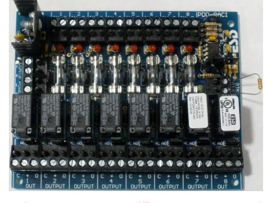
PDB-8F8R Power Distribution for Access Control with Fire Interface module
Controls and Distributes Power with 8 Control Relays with an EOL Fire trigger Interface
Power Interface for Access Control, CCTV, Fire, HVAC, Elevator, and general low voltage system control
Note: Fire, HVAC and Elevator Control has not been evaluated by UL Features:
- 8 Heavy duty Relays with individual Inputs and Status LED's
- Each Relay Input can be Activated from Low Current Open Collector, Normally Closed or Normally Open Switch
- EOL End of Line Resistor Fire Interface Master Trigger de-energizes all Output Relays that are Enabled
- Universal 11 27.5Vdc power input
- Available with Fuses or PTC Circuit Breakers Note: Only the 500mA fuse version of the board has been evaluated by UL Note: The outputs of the PDB-8F8Rare power limited when connected to the AQD3 power-Limited power supply
-
Each Output may be Individually Configured for:
- o Fire Trigger (FT) Enabled or (FTD) Disabled
- o FUSE model can provide optional Dry Contacts
- o N/O or N/C Option Configures the Relay Switched Output
- Each Output 1-8 has a protected, continuous Output and a Relay controlled Output
- TRG LED Green Indicates Trigger Status
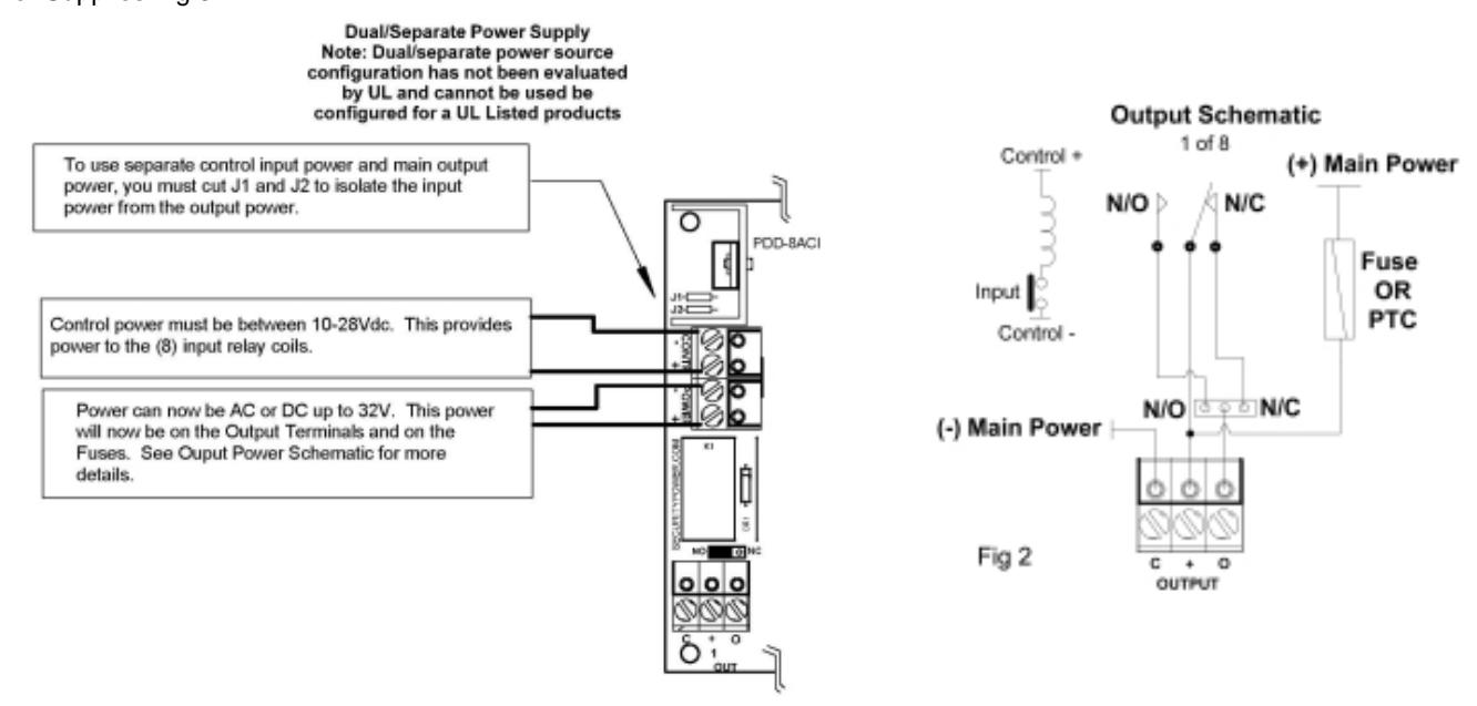
- Control Power and Main Lock Power may be Isolated (Separate Power Supplies) at Users Option Note: Dual/separate power source configuration has not been evaluated by UL and cannot be configured for UL Listed products
- All Terminal Blocks are Pluggable by Channel & Function
- Made in the USA with a Lifetime Warranty
Description / Instructions
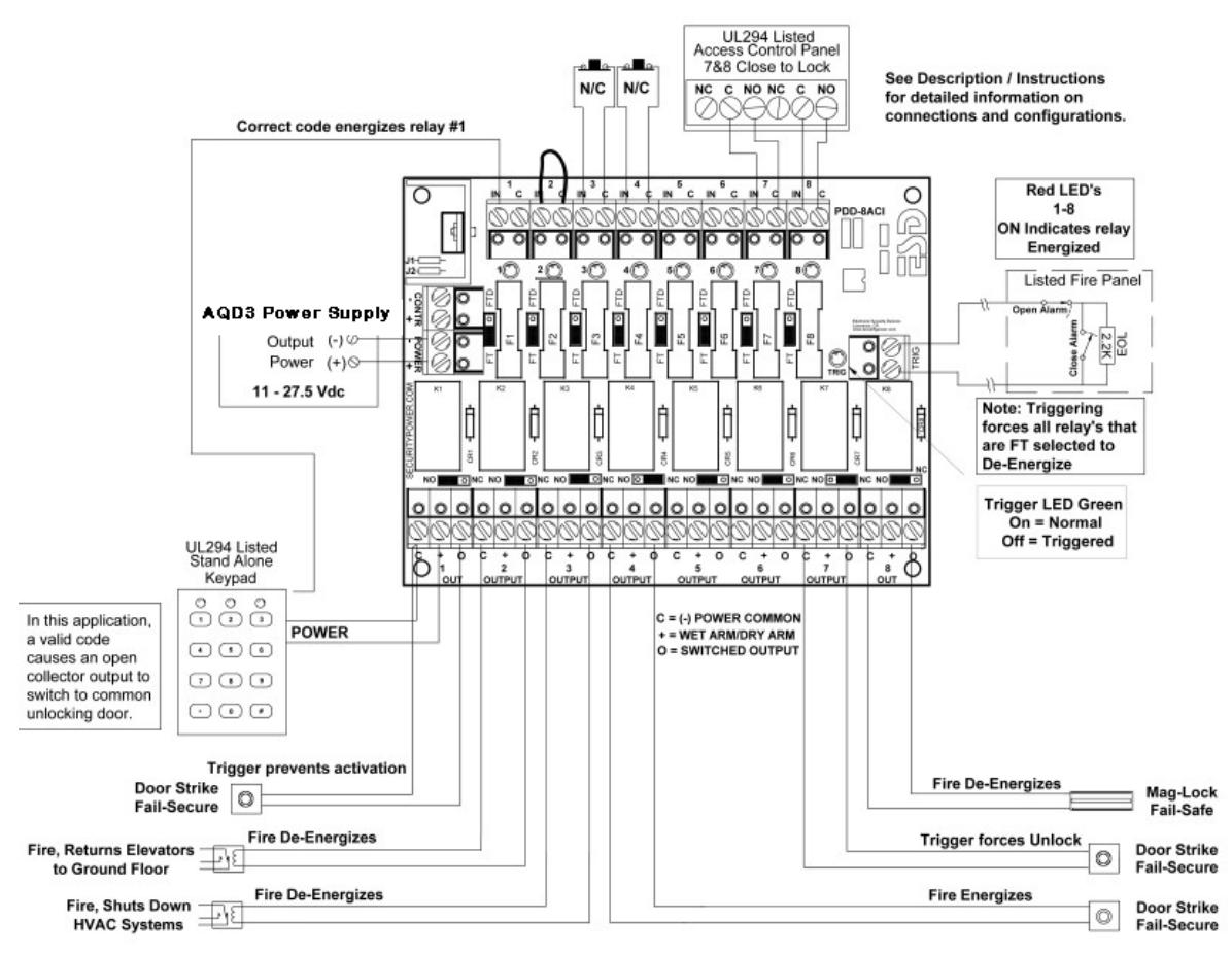
The PDB-8F8Ris a versatile, compact way to distribute and control power for Access Control Systems with Fire Alarm Interface. The PDB-8F8Ris an 8 position power distribution board with individual Relays with input (IN) control for each output (OUT). An EOL resistor trigger input (TRIG), will force all output relays to de-energize that are selected (FT). In a typical installation, the TRIG would be connected to a Fire Alarm panel via a set of contacts. When the Fire Alarm trips, all enabled relays would be forced to be de-energized to unlock electric doors, shut down air systems, and or return elevators to ground floor.
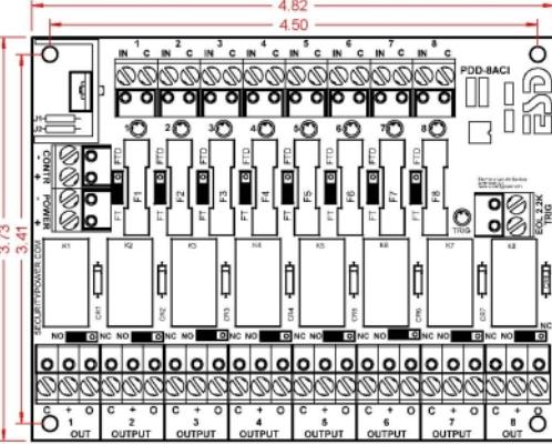
Input / Output Terminals, Jumpers and LED Details and Specifications
Control Power (- CONTR +) Two position un-pluggable terminal block is used to power the coils of the relays. The control voltage must be between 11 and 27.5 Vdc. Each relay energized will draw 20ma of current. By default, Control Power and Main Power are connected together with jumpers J1 & J2 so no connection would be made here unless you were using Dual/separate power as
described below. Note Dual/separate power source configuration has not been evaluated by UL and cannot be configured for UL Listed products.
Main Power (- POWER +) Two position un-pluggable terminal block provides the power to the outputs to be distributed and power to Control through J1 & J2. In a normal application the Power must be between 11 and 27.5 Vdc and would be connected here.
Dual/Separate Power J1 & J2 Jumpers Note Dual/separate power source configuration has not been evaluated by UL and cannot be configured for UL Listed products. J1 Connects (-) Power to (-) Control, J2 Connects (+) Power to (+) Control. By default J1 & J2 are connected together. When J1 & J2 are cut, you must supply 11 to 27.5Vdc to Control power, then you may connect any voltage to 32V AC or DC to the Main Power Terminals. See Dual/Separate Power application figure below.
Inputs (1-8 IN C) Eight, two position un-pluggable terminal blocks. When IN & C are shorted together, the like number output relay will energize. Each relay can also be energized by an open collector that is common to the
Doc.# 500-33045 Rev. A: Installation specifications subject to change without notice
Securitron Magnalock Corporation 10027 S. 51st St., Ste. 102 Phoenix, AZ 85044
ASSA ABLOY, the global leader in door opening solutions.
Phone: (800) MAGLOCK customercare@securitron.com www.Securitron.com
PDB-8F8R Power Distribution for Access Control with Fire Interface module
control power, sinking 20ma for each input. Each of the C's (common) are connected to control negative power.
Input LED's (1-8) Whenever an input is active (relay energized) the associated input red LED will illuminate.
FDT/FT (1-8) Jumpers - These are three pin headers adjacent to each fuse with a shunt with handle that shorts the center pin to FTD or FT.
FTD = Fire Trigger Disabled - When selected, the Trigger will not effect that output.
FT = Fire Trigger – When selected Triggering will force that Input Relay to De-Energize.
Dry/Wet Option (1-8 Fuse Models) Through a Fuse, the (+ Power) is connected to the swing arm of each Relay to distribute power to its output. Removing the Fuse, removes the power from the relay. The (+) now becomes the Common Swing Arm and the "O" is the N/O or N/C contact as selected with jumper.
Outputs (1-8 OUTPUT C, +, O ) Eight, Three position unpluggable terminal blocks. "C" is Power Common and is connected to (- power). "+" is connected to fused (+power) and the relay swing arm. "O" is the relay switched output as selected with N/O or N/C selector jumper
Output Relay Contacts Selector (1-8 NC/NO) Jumpers These 3 pin headers with shunt selectors are located just above each output which selects whether the N/C or N/O contacts are connected to the "O" switched output terminal. With N/C selected, output would be normally ON, or connected to swing arm. With N/O selected, output would turn ON, or close when input is activated. Fire Alarm Interface Trigger (2.2K EOL TRIG) Two position unpluggable terminal block. This input must see the 2.2K ohm EOL (End Of Line) resistor to be in the normal condition. The EOL is to be placed in a Listed fire alarm panel. See Fig 1 illustrating that shorting or opening the EOL will cause the PDB-8F8R to trigger.
TRIG LED (TRIG) Green LED normally ON. Whenever the Trigger is active the LED will be OFF.
Ordering Information
PDB-8F8R "ACI" module only with 500ma Fuses Note: Only the 500ma fuse version of the board has been evaluated by UL No other fuse size or PTC's can be used with a AQD3 .
Specifications
Control (-contr+) ........................... 11–27.5Vdc @ 160mA
Normally no connection is made here. Note: You must add this current to your total device load calculations to be sure your load will be within the rating of the power supply as configured
Main Power (-power+) .................................... 11-27.5Vdc
Note: Must cut J1 & J2 when not using 11-27Vdc power See Dual/Separate power source configuration Note Dual/separate power source configuration has not been evaluated by UL and cannot be configured for UL Listed products.
Total Amps would be equal to the total current of the outputs load plus the module draw of 160ma
Fused/Wet Outputs (12v operation): Max. Output Current.................. 330mA,12V (each output) 2.64 A (total all outputs) Fused/Wet Outputs (24V (each output): Max. Output Current .............. 155mA, 24V (each output): 1.24 A (total all outputs) Dry Outputs: Max. Output Current ............................................ 3A, 30V As evaluated with UL with 500ma fuses Terminal blocks un-pluggable ... 5mm spacing 14–22 awg Fused Outputs 1-8 .............................................. 500mA Littlefuse P/N 217.500 20mm replacement The fused outputs of the PDB-8F8Rare power limited when connected to the AQD3 power-Limited power supply Output Relays 1-8 Dry Contacts are not to exceed ................................................................... 7A or 100VA Trigger Input .................................................... 2.2K EOL Operating Temperature .................................. 0o to +49 o C Mounting Holes ......................................... (4) 3.4" x 4.5" Module Size: ................................ 4.82"w x 3.84h x 1.4"d Weight: ..................................................................... 8oz Mounting Note: Secure 4, #6-32 female/female hex standoffs 7/16" long onto 4, #6-32 studs provided in distribution option space to the right of AQD3 inside E-1485 cabinet back. Place PDB-8F8Ron stand offs with input terminals on top. Secure module with 4, #6-32 x ¼"
Note: All interconnected devices must be UL Listed.
pan head screws. No metal hardware should be larger
UL Approvals for PDB-8F8R
than .28" in Diameter.
UL 294 Access Control System Unit
PDB-8F8R Power Distribution for Access Control with Fire Interface module
PDB-8F8R Typical Applications Single Power Source Application Fig 1
Dual/Se parate
Power Supplies Fig 3