Securitron PB3-LK Push Buttons Installation Instructions
Open the original PDF document
View PDF

SECURITRON PB3-LK ILLUMINATION KITS
1. INTRODUCTION
The PB3-LK is field installable illumination kit intended for the red or green PB3E/EEB3N series push buttons.
2. PRODUCT OVERVIEW
Upon unpacking this product, an inventory should be made to ensure that all the required components and hardware have been included. Along with these instructions, the PB3-LK product should include the following items:
| Part# | Description | PB3-LK |
|---|---|---|
| 030-11000 | 2.2V Green LED | 1 |
| 030-11030 | 1.9V Red LED | 1 |
| 540-32060 | Green Wire w/ Resistor | 1 |
| 540-31090 | Black Wire | 1 |
| 500-15150 | Instructions | 1 |
3. INSTALLATION INSTRUCTIONS
Carefully remove the lens from the push button by grasping the small notches on the top and bottom of lens and pulling straight out. Insert the LED pins into the existing socket. Note the flat spot at the top of the LED flange as shown in Figure 1. It should point toward the top of the switch plate. This is important to maintain the polarity of the LED and to prevent any damage.
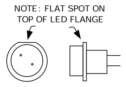
Figure 1
Connect the two wire assemblies by pushing the connectors onto the spade terminals as shown in Figure 2. Care should be taken to not apply excessive force when sliding the connector over the pins. Too much pressure may damage the switch. Resistors are installed on the green wire so that the LED may be operated on either 12 or 24 VDC. If the power supply is 24 VDC, connect directly to the wires. If the power supply is 12 VDC, remove the outer resistor for proper operation at the lower voltage. Apply the 12VDC or 24VDC voltage to the green and black wires to verify operation. Carefully reinstall the lens onto the front of the push button switch assembly by pushing on the lens until it clicks into place.
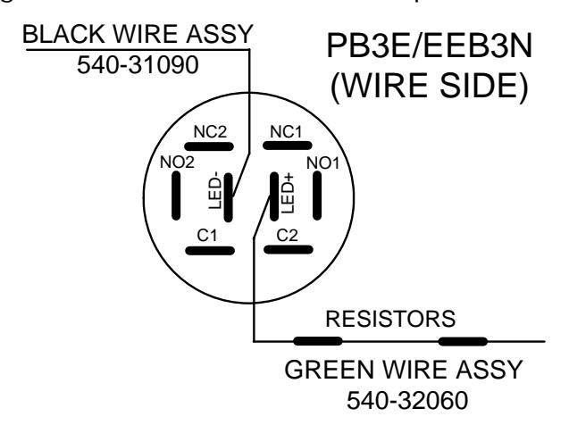
Figure 2