Securitron M680BDCX Electromagnetic Locks Installation Instructions
Open the original PDF document
View PDFM680BDCX MAGNALOCK® SERIES Installation Instructions
|
b
le f T C te ts a o o n n |
|||
|---|---|---|---|
|
S
ci fi ti pe ca o ns |
2 | ||
|
C
nf ig ri O ti o u ng p o ns |
3 | ||
|
lla
id In ti G st a o n u e |
6 | ||
|
W
ir in D ia g g ra m |
14 | ||
|
C
od E rr o r es |
16 | ||
Scan this QR Code for a guided installation video.

Alternatively Quick Clips are available in each section.
Package Contents
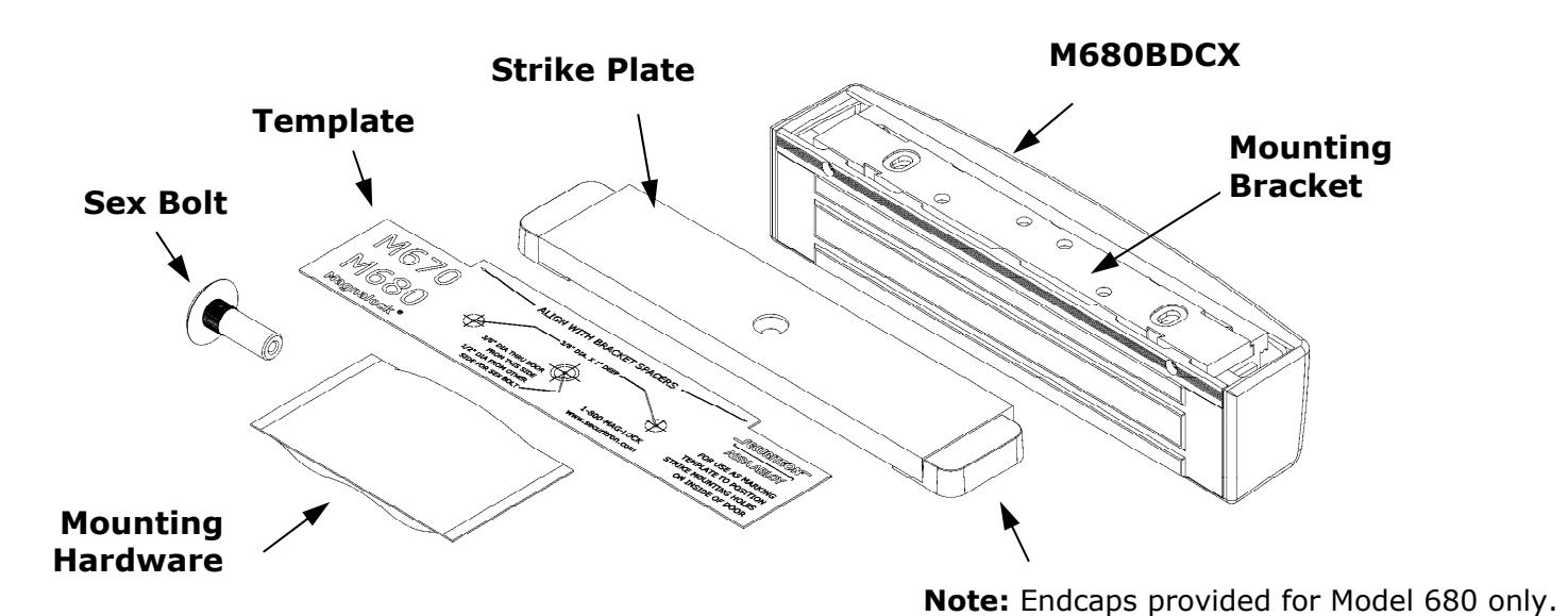
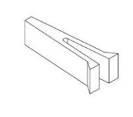
Mounting Hardware
(2) x Bracket Spacer (2) x 1/4-20 Blind Nut
(2) x 1/4" x 1-1/4"

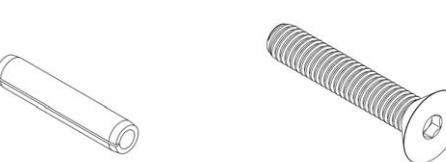
Roll Pin (1) x 5/16-18 x 1-
(1) x – Blind Nut Installation Tool

3/4" Flat Head Socket (3) x – Neoprene Washer
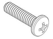
(2) x 1/4-20 x 1" Phillips Pan Head
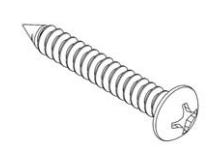
(4) x #12 x 1-1/2" Type A Phillips Pan Head

(4) x #14 x 3" Type A Phillips Pan Head
Recommended Tools
Masking Tape #0, #1 and #2 Phillips Screwdrivers Hammer Measuring Device 1/2" Open End or Crescent Wrench Pencil/Pen Center Punch Wire Strippers/Cutter Multimeter
Fish Tape or Lead Wire 3/16" Hex (Allen) Wrench
Drill bits: 3/16", 7/32" (wood frames only), 3/8", 1/2", 5/8"
M680BDCX Specifications
|
ir
l ( d d ) E ta R n o n m e n e co m m e n e v |
|
|---|---|
|
lt
In ut V p o ag e / 12 24 V D C C nt u rr e lo ck M ag 12 V D C/ 55 0m A ( 10 % ) ± |
O
ti T tu pe ra ng e m pe ra re [ ] 32 ºF t 11 0º F 0º C to 4 3º C o H id it u m y 10 % 90 % t R H o |
|
V
D A ± |
if
ic ti C S a m e ra p e c a o n s |
|
p
o na a m e ra 12 C/ 20 0m ( 10 % ) V D A ± C/ ( ) 24 V D 80 A ± 10 % m |
lo
io C V o r e rs n : H iz l R ol io 52 0 TV L in ta ut or on es n : e |
|
O
ti l P IR p o na 12 C/ 25 ( 10 ) V D A ± % m C/ ( ) 24 V D 10 A ± 10 % m |
id
5Ω V ut t: 1 V 7 eo o pu p- p, llu M in i in io 1. 5 LU X at m n : |
|
T
S it ch R in at a pe m r w g ol 3 0V C ( ) V ta D M im ge ax um – C nt 1 A ur re m p – |
la
ck nd h it io B W V a e e rs n : l R ol H iz io : 4 20 T V Li ta ut or on es n ne V id 1 V 7 5Ω ut t: eo o pu p- p, llu 0 M in i in at io .1 L UX m n : |
|
S
in ( 6 8 0 ly ) D P R at M g o n ol V 3 0V D C ta ge – ( M im ) C 1 25 A nt ax um ur re m – |
|
|
nd
it ch in B ST A T Sw R at o g V ol 3 0V D C ( M im ) ta ge um ax – C nt 1 A ur re m p – |
|
|
R
Ex it S it ch R in st t at eq ue o w g ol 3 0V C ( ) V ta D M im ge ax um – C nt 1 A ur re m p – |
|
|
le
ri l E ct ca 24 C/ 30 0m ( 10 % ) ti l C O |
Magnalock Preparation and Installation
Pre-Installation Survey
Before installing the Magnalock, the mounting location should be determined and assessed for the following:
- Physical strength of the frame should be strong enough to meet or exceed the holding force of the Magnalock. Frame and vicinity should offer protection for the wiring to prevent vandalism
- Door should be inspected for any obstacles that may interfere when mounting the strike plate
- The Magnalock M670/M680 comes with factory default mounting for use with an outswing door. Please contact Securitron for available brackets for other installation configurations.
Magnalock Preparation
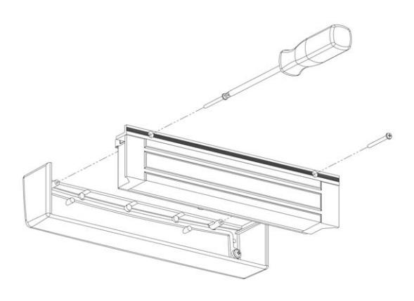
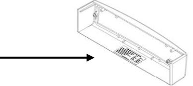
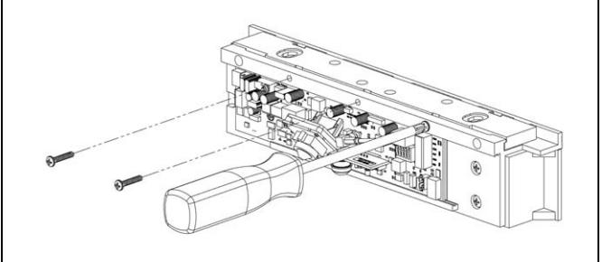
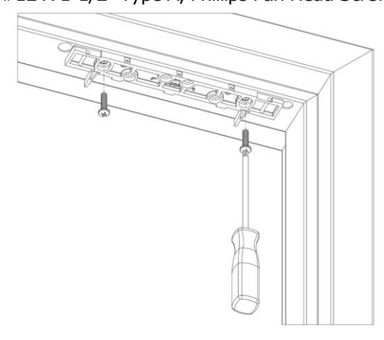
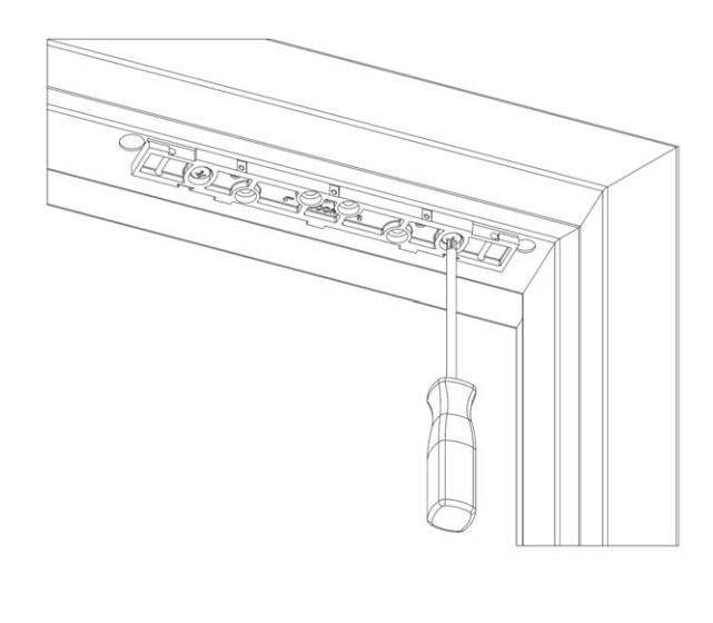
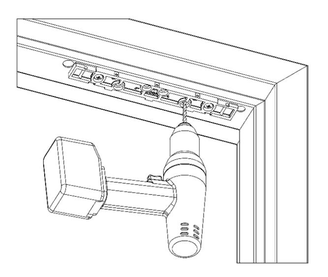
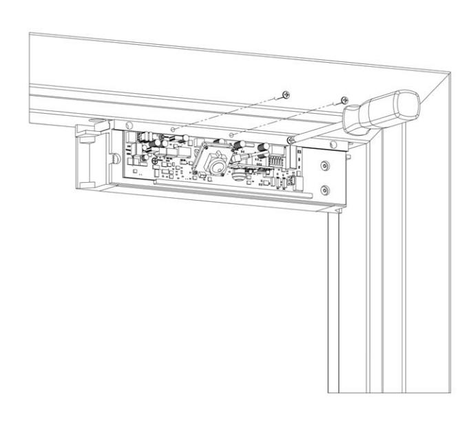
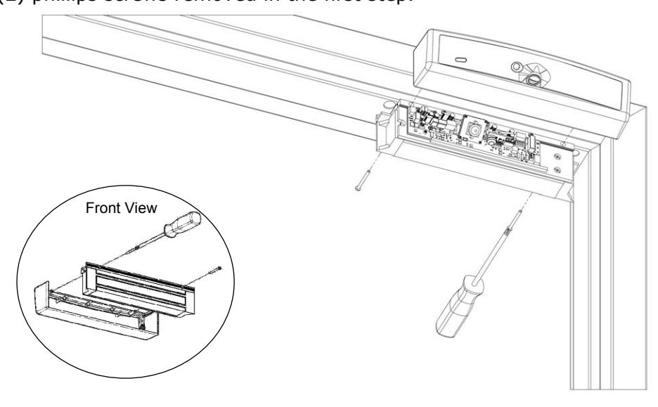
1. Using a Phillips screwdriver, remove the two (2) screws securing the cover as shown. Remove the cover to provide access to the circuit board on the back of the magnet. The screws should be saved to re-attach the cover later.
2.Component Locations
|
C
La b l t o m p o n e n e |
C
N t o m p o n e n a m e |
S
le io ct e n |
P
it io o s n |
|---|---|---|---|
|
J
P 1 J 1 T m p e r a m p e r u : S it h d S le M ct c o e e w th A 3 in j at -p m pe u r ls he nt t ut ut co ro o p fo tt in T se g a m pe r r ch S it S W 1 at w l lo ck T in B J 1 e rm a |
(
C ) ll C lo d N N o rm a se y lo d he C ir it C C cu se w n ov e r lo d ( d ef lt ) C tt in se se g a u |
||
|
(
) lly N O N O o rm a p e n C ir it O he C cu pe n w n ov e r C lo d se |
|||
|
J
P 2 J 2 R st u m p e r : e q u e E it M d S le to ct x o e e 3 in j th A at -p u m pe r ls he nt t ut ut co ro o p in fo th R tt st se g r e eq ue E it ( R EX ) si l in to x g na T in l B lo ck J 8 e rm a Po si ti 3 & 4 o n |
(
O ) lly O N N o rm a p e n cl C ir it O C ir it cu pe n cu os es , he ( d ef lt R EX ct iv n a e a w u ) tt in se g |
||
|
(
N C ) N ll C lo d o rm a y se C C lo d C ir it ir it cu se cu o pe ns , he iv R EX ct w n a e |
|||
|
J
P 3 J 3 u m p e r : it io D P o o o r s n d le M S ct o e e th A 3 in j at -p m pe u r ls he nt t ut ut co ro o p fo th tt in D se g e oo r r S ch ( PS ) Po si ti it D o n w in in l lo ck 8 T B J e rm a si ti & 2 Po 1 o n |
(
N C ) N ll C lo d o rm a y se C ir it C lo d he is D cu se w n oo r C lo d ( d ef lt in ) tt se a u se g |
||
|
(
O ) lly O N N o rm a p e n he C ir it O D is cu pe n w n oo r lo d C se |
|||
|
J
P 4 J 4 m p e u r : b le L E D E n a th A 2 in j at -p u m pe r b le th LE D e na s e |
L
E D E N A B L E D ( d ef lt in ) tt a u se g |
||
|
IS
L E D D A B L E D ( ed ) ju m pe r re m ov |
|||
|
J
P 5 J 5 u m p e r : C lo S L E D o r A 2 in j -p m u ls he nt t co ro c O LE D ut ut o p ti o p o ns a re r g re e n |
le
ct e th at pe r lo of he t o r |
S
E C U R E R E D L E D = ( d ef lt ) tt in a se g u |
|
|
ut
ut p ed o r |
S
E C U R E G R E E N L E D = ( ju ed ) m pe r re m ov |
|
S
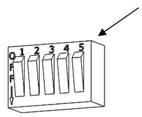
2 W |
S
it h D IP c w : |
E
N A B L E P IR |
S
ch O it 5 N w |
|---|---|---|---|
|
b
le d P IR E n a a n la le io D S ct e e n y |
nd
d la 5 se co e y |
S
it ch 3 O ( d ef lt ) FF w a u |
|
|
10
nd d la s ec o e y |
S
it ch 3 O N w |
||
|
it
h D IP S w c : A R lo k T im to u e c e r E b le d D la n a a n e y S le io ct e n he lo ck la T A ut R D o e e y d b le d by T im is is e a r d ef lt he d la . T a u e y ca n be b le d by ti et e na s ng S it ch 4 O N nd t w o a , th le in ti ct e n se g a m e d la it h S it ch 1 nd e y w w a S it ch 2 w |
la
im D IS A B L E D T e y e r |
ch
( d ef lt ) S it 4 O FF w a u |
|
|
la
im E N A B L E D T e y e r |
ch
S it 4 O N w |
||
|
nd
d la 5 se co e y |
ch
ch S it 1 O FF S it 2 O FF w w , |
||
|
10
nd d la s ec o e y |
S
it ch 1 O FF S it ch 2 O N w w , |
||
|
2
0 nd d la se co e y |
S
it ch 1 O N S it ch 2 O FF w w , |
||
|
3
0 nd d la se co e y |
S
it ch 1 O N S it ch 2 O N w w , |
||
|
J
1 |
T
in l B lo k 1 e rm a c T S it h a m p e r w c |
A
2 ir in l b lo ck id in S PD T th te nt t at -w e rm a p ro v g a co ac ch d in ed b JP 1 he th is ta te et a ng es s a s e rm y w n e co v e r ed be ed b S W 1 t se ns o r e m ov y |
|
|
J
5 |
in
l lo k T B 5 e rm a c In P t p u o w e r |
l
b lo ck id he A 3 ir in in io te ct to t -w e rm a p ro v g co n ne n p ow e r ly ( ) fo nd Po si ti 1 is P IR ta nt + su p p o n a c o ns r ca m e ra a ( ) fo th lo ck ( -) Po si ti 2 is it io 3 is + o n r e p ow e r, p os n |
|
| J6 |
in
l lo k 6 T B e rm a c d S B T A T o n |
3
l b lo ck id S C A ir te in in PD T 1- Fo e rm a p ro g a rm -w v th ha he th nd S b nd nt t at ta te B T A T i co ac c ng es s n e o o s w d in te te p rr u |
|
| J8 |
T
in l B lo k 8 e rm a c D P it io S it h o o r o s n w c |
A
6 ir in l b lo ck id in te w e rm a p ro v g : ( 2 ) S PS d ed b 3 ba d 1- T nt t et in Ju co ac e rm m pe se o n y r d ch si ti it oo po o n sw r ( ) ch d ed b 3 -4 S PS T is in Ju nt t st at et co ac e a ng e e rm y m pe r ba d 2 R EX iv io ct at se o n a n ( 5 -6 ) 2 si ti d lo d is b le PI R nt t, po o n ry c o ac c su re a s |
|
|
b
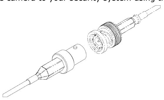
le B N C C a |
fo
B N C C ct o n n e o r r ig l C S a m e ra n a |
he
lu d ed b le be ed h h he d T i B N C it si ut t nc c a c a n r o ro ug e r e of he lo ck h fo ill in io t ct to m ag o us g r co n ne n s u rv e a nc e st e m sy |
|
3.Document Configuration Settings
The Board Settings are now complete. Copy your settings onto the adhesive-backed Circuit Board Settings label enclosed with the mounting hardware packet.
M670/M680 Settings www.securitron.com Jumper 4 (JP4) LED Enable ENABLED DISABLED Jumper 5 (JP5) LED SECURE Color RED GREEN *Jumper 1 (JP1)Tamper Select Mode NC 1-2 NO 2-3
*Jumper 2 (JP2) Request to Exit Mode NO 1-2 NC 2-3 *Jumper 3 (JP3) Door Position Mode NC 1-2 NO 2-3
*Delay (in seconds) 0 5 10 20 30 * available on select models 1-800-MAGLOCK
*(SW2) Auto Relock Delay ENABLED DISABLED
Important! Complete the label and affix to the inside cover of your Magnalock ®
This information will be needed if the lock needs to be serviced, replaced or inspected.
Magnalock Installation
1. Remove three (3) screws securing lock to mounting bracket and slide the bracket from the top of the lock chassis.
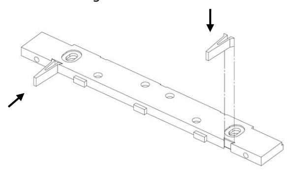
2. Pinch and insert spacers flush into the dovetail slots of the lock-mounting bracket.
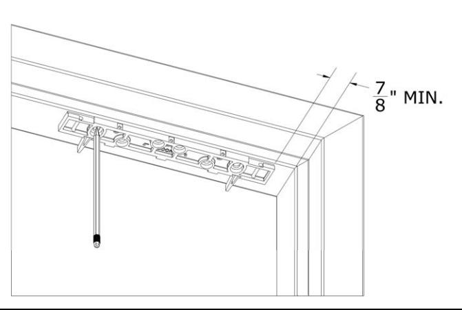
3.Mark Mounting Holes:
Use masking tape to protect the door and frame surfaces during marking and drilling. Place the lock bracket on the secure side of the door against the frame stop toward the side of the door that does not have hinges. Close the door and adjust the bracket so that the spacers rest against the door. Mark the frame through the two (2) oblong bracket mounting holes.
Note: Maintain 7/8" minimum clearance from the frame
Quick Clip 2: Mounting the
Bracket
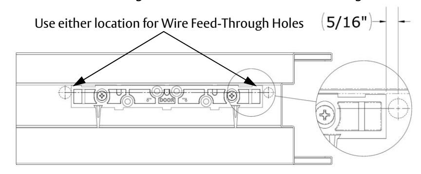
4.Mark Wire Feed-Through Holes:
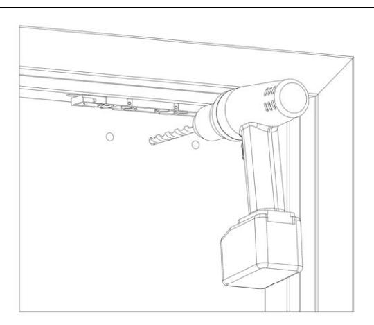
Mark the frame for wire feed-through hole at the end closest to where you will access the wire run. These holes should be toward the rear edge of the mounting bracket and be adjacent to the end of the bracket as shown. Remove mounting bracket from frame when drilling holes.
5.Metal Door Frame - Drill Mounting Holes:
Note: If installing on a wood door frame, go to Step 7.
Drill two (2) 3/8" diameter holes at bracket-mounting hole marks.
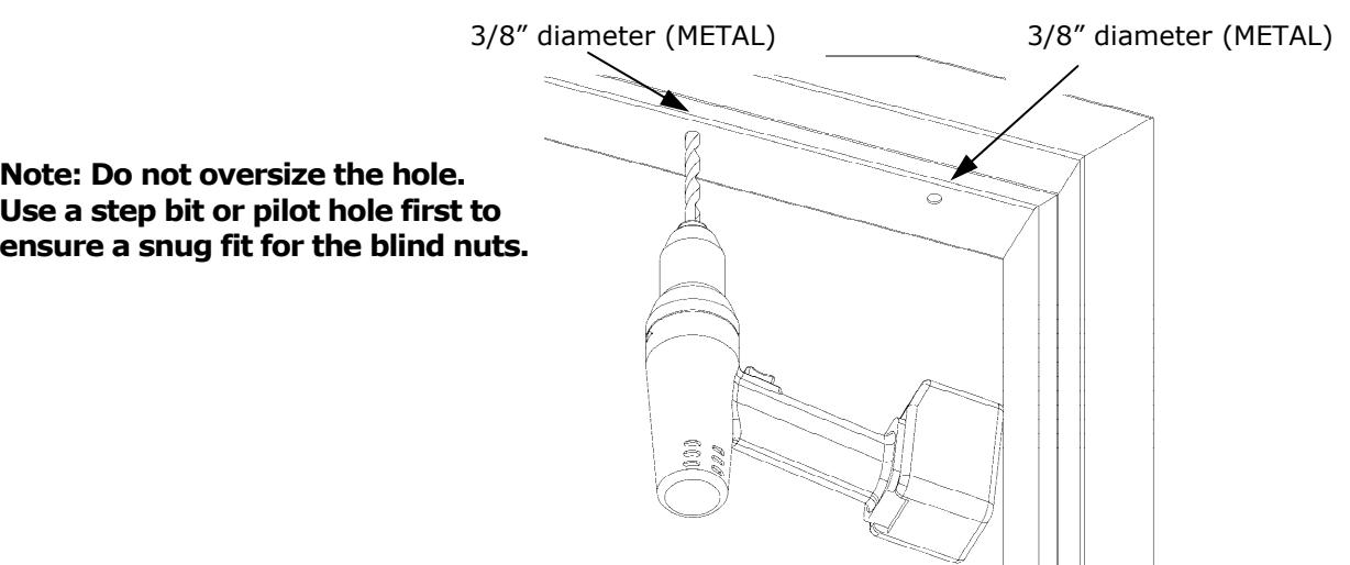
6.Blind Nut Installation:
Note:
Use the tool provided to install blind nuts into each 3/8" diameter hole. Hold the collapsing nut with a 1/2" box end wrench. Maintain pressure on the mounting surface, while using a 3/16" hex wrench to tighten the cap screw and collapse the blind nut. Go to Step 8.
Why Use Blind Nuts?
Blind nuts provide a highly secure and tamper resistant system for mounting and are the mounting hardware provided for this unit.
Only use approved included hardware for mounting.

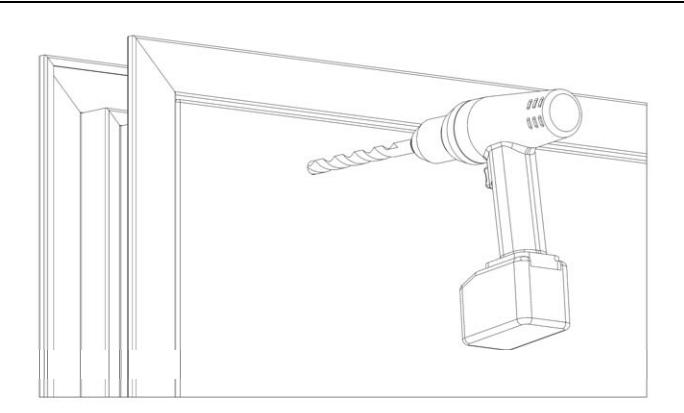
7.Wood Door Frame – Drill Mounting Holes:
Drill two (2) 3/16" diameter holes at bracket-mounting hole marks.
Drill 1 ¼" deep.
3/16" diameter (WOOD)
3/16" diameter (WOOD)
8.Drill Wire Access Holes
Drill wire access holes as needed on one (1) or both sides of the bracket location.
1/2" diameter is recommended for wire access.
5/8" diameter is recommend for camera wiring.
9.Install Bracket:
Use a Phillips screwdriver to temporarily install the bracket with spacers against the closed door. Metal Frames: Use two (2) 1/4-20 X 1" Phillips Pan Head Screws and apply included thread lock to screw threads
Wood Frames: Use two (2) #12 X 1-1/2" Type A, Phillips Pan Head Screws.
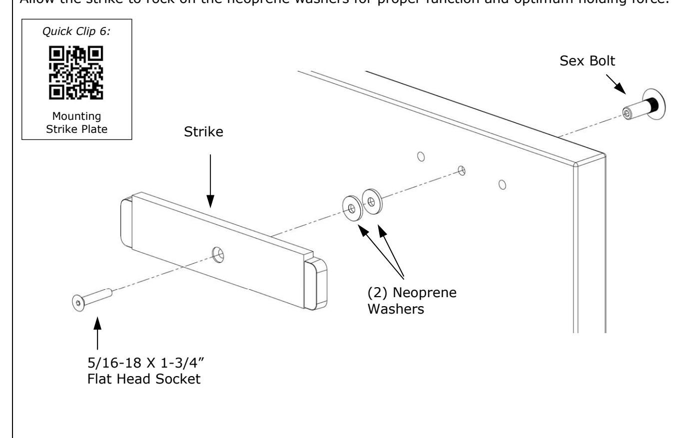
Strike Installation
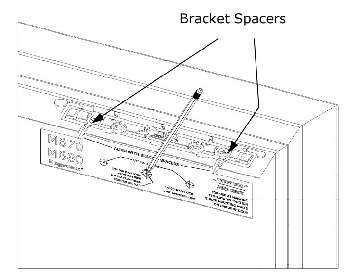
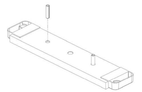
1. Close the door and place the template between the bracket spacers. Mark the strike plate hole locations.
Bracket spacers can now be removed from the bracket.
Quick Clip 4:
Strike Installation
2.From INSIDE the door:
Drill one (1) 3/8" diameter hole for the sex bolt through the door at the strike mounting center mark.
Drill two (2) 3/8" diameter x 1" deep holes at each side mark for the strike alignment roll pins. Do not drill through the door.

3.From OUTSIDE the door:
For a Hollow Metal Door : Drill out the 3/8" diameter strike mounting hole to 1/2" diameter in the outer wall only . For a Solid Wood Door : Drill out 3/8" diameter strike mounting hole to 1/2" diameter; drill completely through .
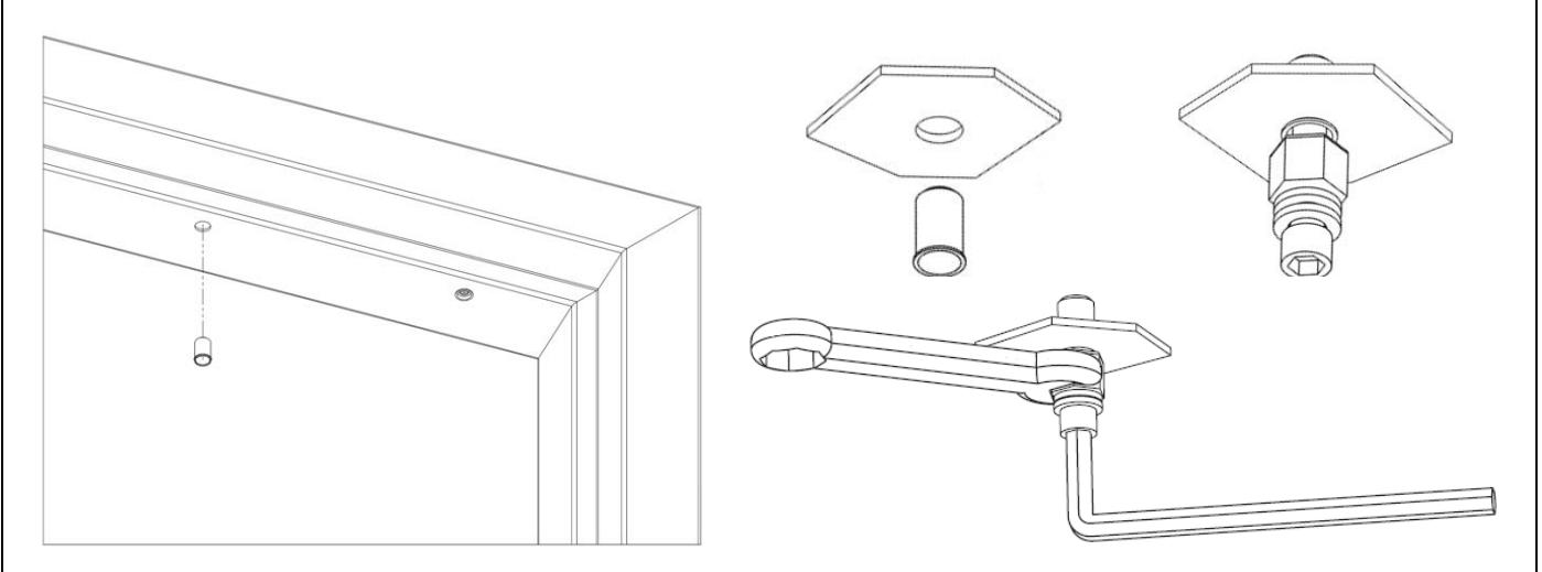
4.Install Roll Pins into Strike Plate:
Remove the two (2) roll pins from the hardware packet. Insert a roll pin into each of the holes in back of strike. Gently tap into place using a hammer.
5.Secure Strike Plate to the Door
Apply the included threadlock compound to the 5/16-18 X 1-3/4" flat head socket screw. Pass the 5/16-18 X 1-3/4" flat head socket screw through the strike plate, two (2) neoprene washers, door and into the sexbolt as illustrated.
Use a 3/16" hex wrench to tighten the screw into the sex bolt. (While tightening, use a hammer to gently tap the head of the sex bolt until the head sits flush with the door).
Do NOT over-tighten the assembly, the neoprene washers should not be compressed. Allow the strike to rock on the neoprene washers for proper function and optimum holding force.
Adjustments:
1.Assemble Lock to the Bracket and Adjust:
Loosen the two screws securing the mounting bracket to the door frame so that the bracket can move.
Slide the lock onto the mounting bracket and test fit against the strike plate with the door closed. Slide the lock so that the entire face makes contact with the strike plate.
Mark back edge of mounting bracket at each end and remove the lock from the bracket.
2. Ensure that the mounting bracket aligns with the marks and tighten the mounting screws.
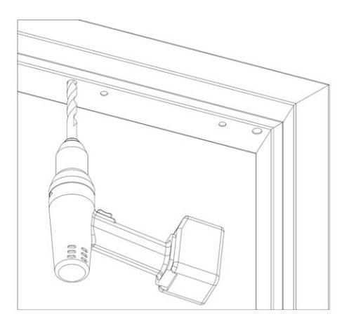
3.Drill Frame for Anchor Screws:
Using the mounting bracket as a template, drill the four remaining holes in the frame for the anchor screws.
Metal Frames: Drill 3/16" diameter holes. Wood Frames: Drill 7/32" diameter holes.
4.Install Anchor Screws:
Using a Phillips screwdriver, install the four (4) anchor screws.
Metal Frames: Use #12 X 1-1/2" Type A, Phillips Pan Head Screws.
Wood Frames: Use #14 X 3" Type A, Pan Head Screws.
Final Installation:
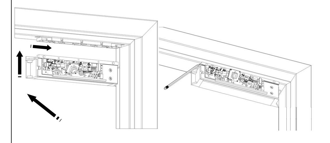
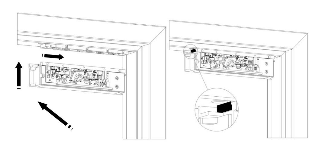
1. Insert the top of the Magnalock chassis at the end of the mounting bracket. Slide the lock chassis to the center of the bracket.
The edge of the lock chassis must be flush with the end of the mounting bracket when centered (see inset).

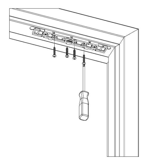
2. Using a Phillips screwdriver, install the three (3) 6-32 X 3/4" Phillips pan head screws to secure the lock chassis to the mounting bracket.
Final Wiring
1. Pull wires/cables through the wire feed-through hole(s) that are drilled in the frame. A small screwdriver has been included to help make connections to the terminal blocks as required.
The end user and installer are liable for Fire and Building code compliance.
2. The following diagram shows a basic wiring configuration for the Magnalock.
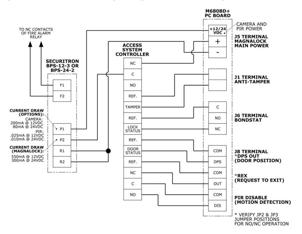
M680BDCX
3. Motion Detector models : Enable the motion detector by locating DIP Switch SW2, and setting Switch 5 to ON. REX timer is set with Switch 3. OFF= 5 seconds, ON= 10 seconds
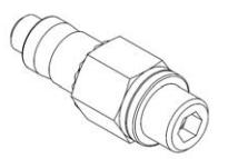
Camera Models : Connect the camera to your security system using the included BNC cable.
4. After installation and wiring have been completed, re-install the lock cover through the lock chassis using the two (2) phillips screws removed in the first step.
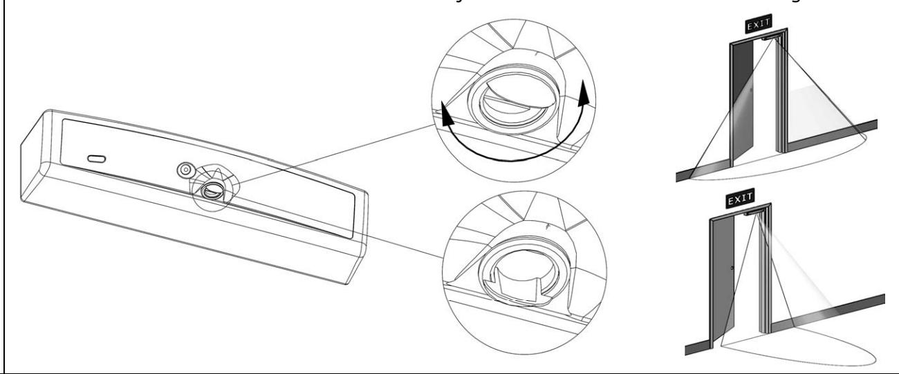
5. Adjusting the field of the infrared motion detector.
The infrared motion detector can be easily adjusted after installation to cover the desired approach area. Rotate the black reflector as shown to adjust from a narrow to a wide coverage area.
MAGNALOCK MAINTENANCE
Visual Inspection
Check the rubber washers for elasticity and proper pivoting. Tighten as required.
Check for build-up of debris on the Magnalock and strike armature.
Check for rust on the Magnalock and strike plate armature. Clean as required.
Cleaning Methods
Apply rubbing alcohol onto a clean cloth and thoroughly wipe down the Magnalock and strike plate armature.
Cleaning once a year is recommended.
Clean every three to six months where rusting occurs.
Use a plastic dishwashing scrub pad to aid in the removal of rust.
DO NOT USE PETROLEUM BASED PRODUCTS FOR CLEANING DO NOT USE STEEL WOOL BASED SCRUB PAD OR SANDPAPER
Troubleshooting Guide:
|
P
O S S IB L E IS S U E S |
T
R O U B L E S H O O T IN G T IP S |
|
|---|---|---|
|
lo
N o po e o p ow e w r r w r |
C
nf ir lt nd lo ck nt t M t o m v o ag e a c u rr e a ag na o sp ec |
|
|
(s
) 2 ee p ag e |
||
|
he
ck ha th ll fi ed C D C P S is F W R ti t t e ow e r o u rc e u av e ec |
||
|
(
lf ti fi ed C is b le ) H R A ta a w av e ec o r p ow e r u na cc e p |
||
|
ed
ed ld R H in Fo uc o g rc e |
C
he ck ik la it io nd ri io tr te nt at s e p p os n a o e n |
|
|
C
le rf nd he ck f bs ti tr a n su ac es a c o r o uc o ns |
||
LED Error Codes:
Note LED Jumper J4 must be installed (LED ENABLED) for error codes to be visible
|
C
O D E |
S
T A T E |
S
O L U T IO N |
|---|---|---|
|
le
ed lo S EC U R E ct se c o r, ly in nt o n co uo us |
l O
h N ti it o rm a pe ra o n w lo d D C oo r se |
rk
lly le ed S in S EC U R E st ct y e m w o g no rm a se , lo be le ed h it Ju JP 5 S ct co r ca n s e w m pe r ee 4 pa g e |
|
O
-S EC le ed N N U R E ct se lo ly nt in co o n co uo us r, |
l O
h N ti it o rm a pe ra o n w O D oo pe n r |
S
rk lly st in e m o g no rm a y w |
|
/
G in R E D R E E N nt co uo us fl h as |
Pr
E oc es so r rr o r |
C
he ck ll io if is ct ts a co n ne ns e rr o r pe rs , la it re p ce u n |
|
la
sh f 3 Fa F st es o lo S EC U R E 5 co r ev e ry nd se co s |
M
V lt ha t ag ne o ag e s d d be lo 8 5 % ro p pe w |
C
he ck lt nd M lo ck nt at v o ag e a cu rr e ag na io C he ck D C P S is F ll ct co n ne ns ow e r o u rc e u fi ed W R ti av e ec |
|
le
la sh be S in F A g m r nd 5 ev e s ec o s ry |
nd
ft id B E Le S o o e rr r – |
he
ck ik la nd C tr te it io ri nt at io s e p p os n a o e n le rf nd he ck f bs C tr ti a n su ac es a c o o uc o ns r |
|
b
le la sh be D F A o m u r nd 5 ev e ry s ec o s |
nd
ht S id B E R ig o o e rr r – |
C
he ck ik la nd tr te it io ri nt at io s e p p os n a o e n C le rf nd he ck f bs ti tr a n su ac es a c o r o uc o ns |
|
ff
O |
LE
D d is b le d a |
C
he ck ha LE D i b le d it h Ju t t at s e na w a m pe r JP 4 C he ck lt nd J5 nt t v o ag e a c u rr e a |
Problems with Installation?
Call Securitron: 1-800-MAGLOCK
For warranty information: visit www.securitron.com/en/site/securitron/About/MagnaCare-Warranty/