Securitron M370, M380BD Electromagnetic Locks Installation Instructions
Open the original PDF document
View PDFM370/M380BD MAGNALOCK® SERIES Installation Instructions
Table of Contents Specifications 2 Configuring Options 3 Installation Guide 6 Wiring Diagram 14 Error Codes 16
Scan this QR Code for a guided installation video.

Alternatively Quick Clips are available in each section.
Package Contents
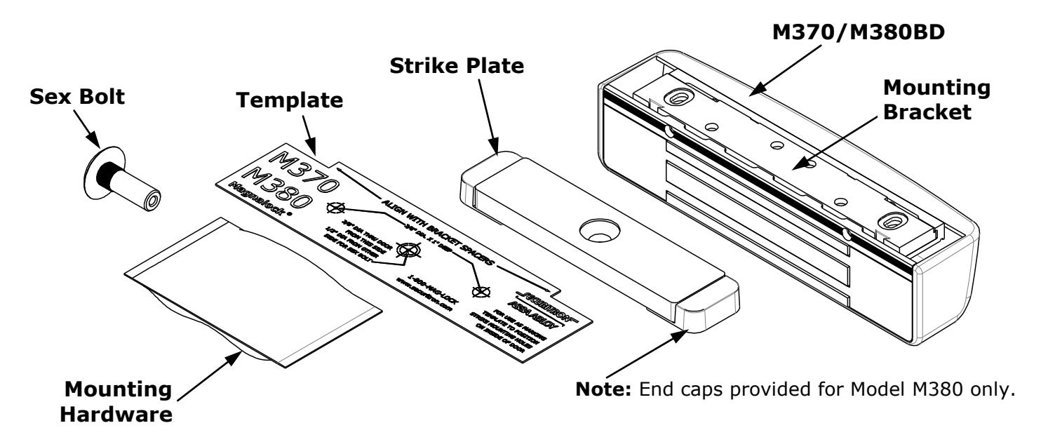
Mounting Hardware
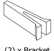
(2) x Bracket Spacer
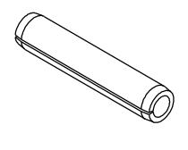
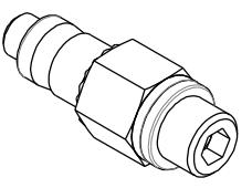
(2) x 1/4" x 1- 1/4" Roll Pin
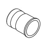
(2) x 1/4-20 Blind Nut (1) x – Blind Nut
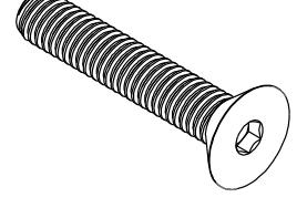
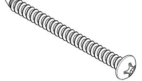
(1) x 5/16-18 x 1-3/4" Flat Head Socket
Installation Tool

(3) x – Neoprene Washer
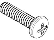
(2) x 1/4-20 x 1" Phillips Pan Head

(1) x Plastic Strike Bushing
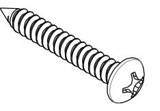
(4) x #12 x 1-1/2" Type A Phillips Pan Head
(4) x #14 x 3" Type A Phillips Pan Head
Recommended Tools
Masking Tape #1 and #2 Phillips Screwdrivers Hammer Measuring Device 1/2" Open End or Crescent Wrench Pencil/Pen Center Punch Wire Strippers/Cutter Multimeter
Fish Tape or Lead Wire 3/16" Hex (Allen) Wrench
Drill bits: 3/16", 7/32" (wood frames only), 3/8", 1/2"
M370 / M380BD Specifications
| Mechanical | Electrical | Environmental (Recommended) |
|---|---|---|
|
Physical Size:
Height: 2.20" [56mm] |
Input Voltage
12/24 VDC |
Operating Temperature
32ºF to 110ºF [0ºC to 43ºC] |
|
Depth: 2.45" [62mm]
Length: 10.00" [254mm] |
Current
M370 12VDC/500mA (±10%) |
Humidity
10% to 90% RH |
| Shipped Weight: | 24VDC/275mA (±10%) | |
| Weight: 6 lbs | M380BD | |
| Holding Force (Maximum) |
12VDC/530mA (±10%)
24VDC/310mA (±10%) |
|
| 600 lbs [272 kg] | Tamper Switch Rating | |
| UL Tested Ratings: | Voltage – 30VDC (Maximum) | |
|
Static Holding Force: 500 lbs
[227 kg] |
Current – 1 Amp
DPS Rating (M380 only) |
|
|
Dynamic Holding Force: 50 ft
lbs [68 J] |
Voltage – 30VDC
(Maximum) Current – 125mA |
|
| Endurance: 250,000 cycles |
Magnalock Preparation and Installation
Pre-Installation Survey
Before installing the Magnalock, the mounting location should be determined and assessed for the following:
- Physical strength of the frame should be strong enough to meet or exceed the holding force of the Magnalock.
- Frame and vicinity should offer protection for the wiring to prevent vandalism.
- Door should be inspected for any obstacles that may interfere when mounting the strike plate.
- The Magnalock M370/M380 comes with factory default mounting for use with an outswing door. Please contact Securitron for available brackets for other installation configurations.
PN# 500-23300 Page 2 Rev. B, 07/13
Magnalock Preparation
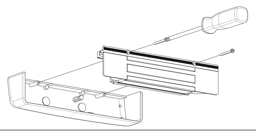
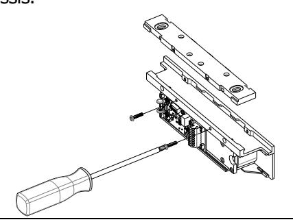
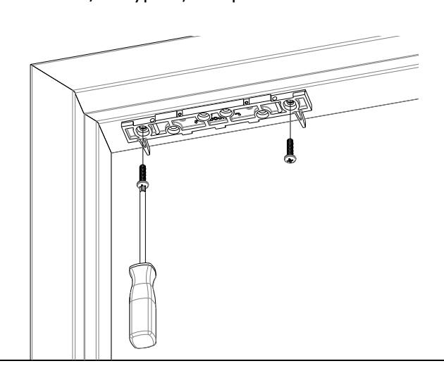
1. Using a Phillips screwdriver, remove the two (2) screws securing the cover as shown. Remove the cover to provide access to the circuit board on the back of the magnet. The screws should be saved to re-attach the cover later.
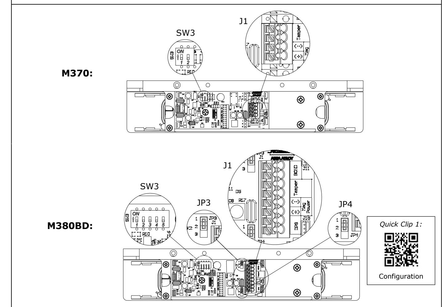
2. Component Locations
| Component Label | Component Name | Selection | Position |
|---|---|---|---|
| SW3 |
DIP Switch SW3.1:
LED Enable Position 1 setting of the |
ON
= LED ENABLED |
Position
1 ON (default) |
|
(M370 has a
2-position DIP) |
DIP switch
enables or disables the display of the LED for lock status. |
OFF
= LED DISABLED (default setting) |
Position
1 OFF |
| SW3 |
DIP Switch SW3.2:
LED Color Select Position 2 setting of the DIP switch controls the color of the LED output. Output options are red or green. |
ON = SECURE = RED |
Position
2 ON |
|
OFF = SECURE = GREEN
(default setting) |
Position
2 OFF (default) |
||
| SW3 |
DIP Switch
SW3.3, SW3.4 and SW3.5: |
DISABLE Delay Timer |
Position
3 OFF (default) |
|
Auto Relock Timer
Enable and Delay Selection |
ENABLE Delay Timer |
Position
3 ON |
|
| (Auto Relock Timer |
The Auto Relock Delay
Timer is disabled by default. The delay can be enabled by setting the position 3 switch of SW3 to ON, and then selecting a time delay with Position 4 and Position 5 of SW3. |
5 second delay |
Position
4 OFF Position 5 OFF |
|
available on M380
models only) |
10 second delay |
Position
4 OFF Position 5 ON |
|
| 20 second delay |
Position
4 ON Position 5 OFF |
||
| 30 second delay |
Position
4 ON Position 5 ON |
||
|
JP3
(available on M380 models only) |
Jumper 3:
BondSTAT Mode Select A 3-pin jumper that controls the output setting for the BondSTAT in Terminal Block J1 Position 7 & 8. |
(NC) Normally Closed
Circuit Closed when Bond is secure (default setting) |
|
|
(NO) Normally Open
Circuit Open when Bond is secure |
|||
|
JP4
(available on M380 models only) |
Jumper 4:
Door Position Mode Select A 3-pin jumper that controls the output |
(NC) Normally Closed
Circuit Closed when Door is Closed (default setting) |
|
|
setting for the Door
Position Switch (DPS) in Terminal Block J1 Position 1 & 2. |
(NO) Normally Open
Circuit Open when Door is Closed |
|
J1
(M370) |
Terminal Block 1 | (M370 has a 4-position terminal block) | |
|---|---|---|---|
|
Position 1 & 2:
Input Power |
Terminal positions 1 & 2 provide
a connection point for positive (+) and negative (-) 12 and 24 VDC power connection. |
||
|
Position 1 = (+) Positive
Position 2 = (-) Negative |
|||
|
Position 3 & 4:
Tamper Indication |
Terminal positions 3 & 4 of the terminal block provide
connection for tamper sensing. Signal continuity is disrupted whenever the cover is removed. |
||
| J1 (M380) | Terminal Block 1 | (M380 has an 8-position terminal block) | |
|
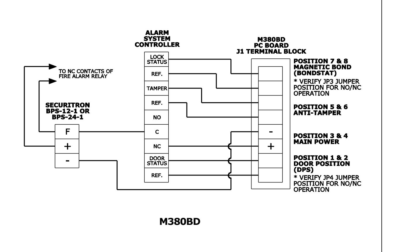
Position 1 & 2:
Door Position Switch |
Terminal positions 1 & 2 provide
a set of contacts of which state change is determined by Jumper 4 (JP4) based on the strike plate's proximity to the lock face. |
||
|
Position 3 & 4:
Input Power |
Terminal positions 3 & 4 provide
a connection point for positive (+) and negative (-) 12 and 24 VDC power connection. Position 3 = (+) Positive Position 4 = (-) Negative |
||
|
Position 5 & 6:
Tamper Indication |
Terminal positions 5 & 6 provide connection for tamper
sensing. Signal continuity is disrupted whenever the cover is removed. |
||
|
Position 7 & 8:
BondSTAT |
Terminal positions 7 & 8 provide
a set of contacts of which state change is determined by Jumper 3 (JP3) based on the strike plate's magnetic bond to the lock face under power. |
||
3. Document Configuration Settings
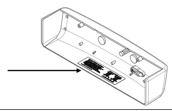
The Board Settings are now complete. Copy your settings onto the adhesive-backed Circuit Board Settings label enclosed with the mounting hardware packet.
* available on M380BD models only
M370/M380 Settings www.securitron.com 1-800-624.5625
ON=ENABLED ON=RED 1-2=NC 1-2=NC ON=ENABLED OFF=DISABLED OFF=GREEN 2-3=NO 2-3=NO OFF=DISABLED 5 10 20 30
Note: The example shows the Default settings. Your settings may vary, based on your checklist.
NO = N ormally O pen NC = N ormally C losed
Important! Complete the label and affix to the inside cover of your Magnalock ®
This information will be needed if the lock needs to be serviced, replaced or inspected.
Magnalock Installation
1. C H 1 Remove two (2) screws securing lock to mounting bracket and slide the bracket from the top of the lock chassis.
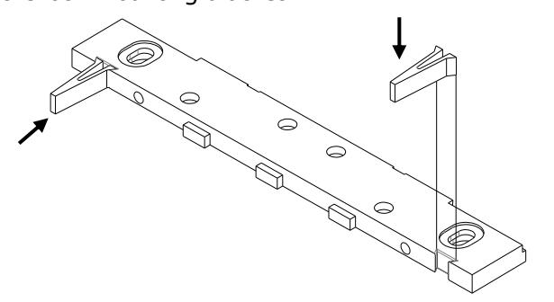
2. Pinch and insert spacers flush into the dovetail slots of the lock-mounting bracket.
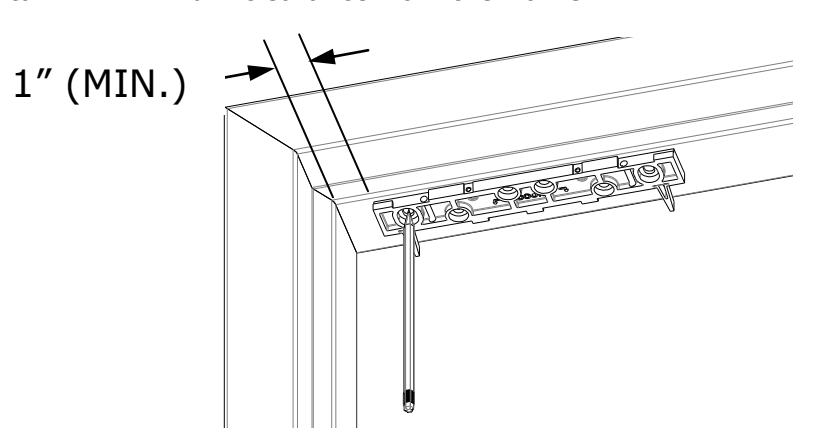
3. Mark Mounting Holes:
Use masking tape to protect the door and frame surfaces during marking and drilling. Place the lock bracket on the secure side of the door against the frame stop toward the side of the door that does not have hinges. Close the door and adjust the bracket so that the spacers rest against the door. Mark the frame through the two (2) oblong bracket mounting holes.
Note: Maintain 1" minimum clearance from the frame.

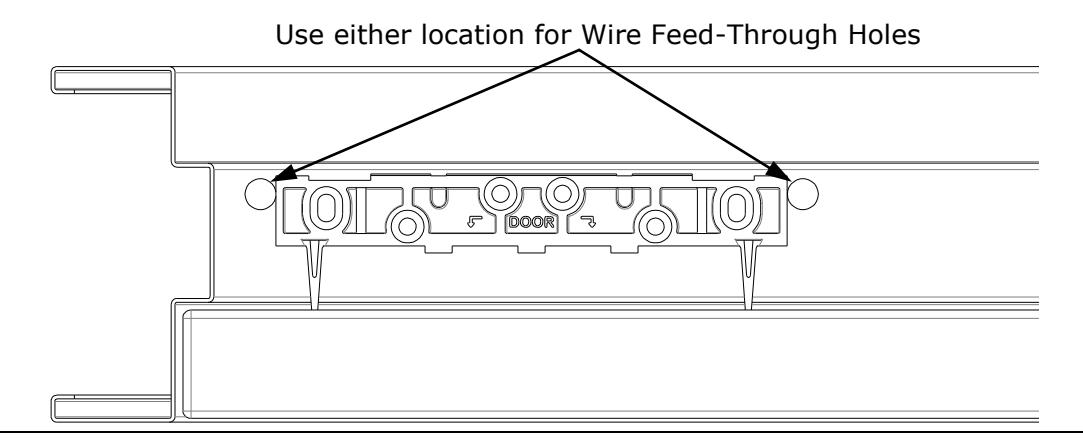
4. Mark Wire Feed-Through Holes:
Mark the frame for wire feed-through hole at the end closest to where you will access the wire run. These holes should be toward the rear edge of the mounting bracket and be adjacent to the end of the bracket as shown. Remove mounting bracket from frame when drilling holes.
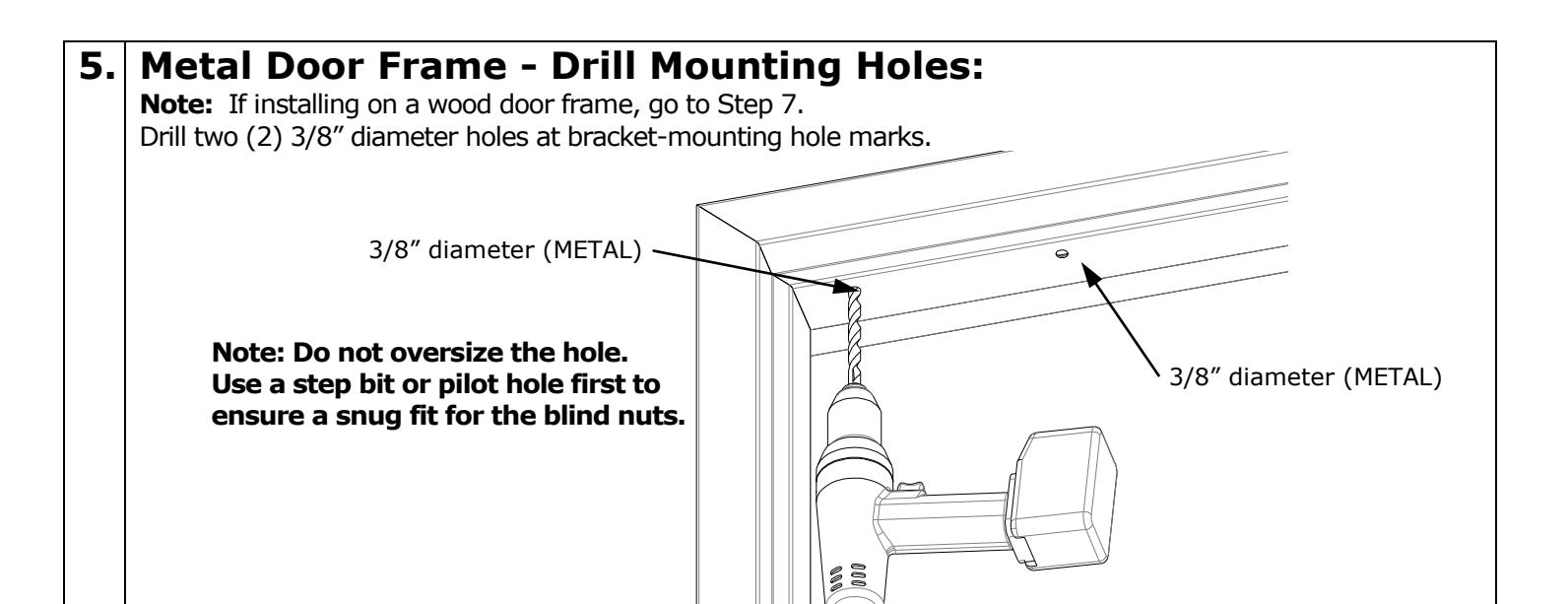
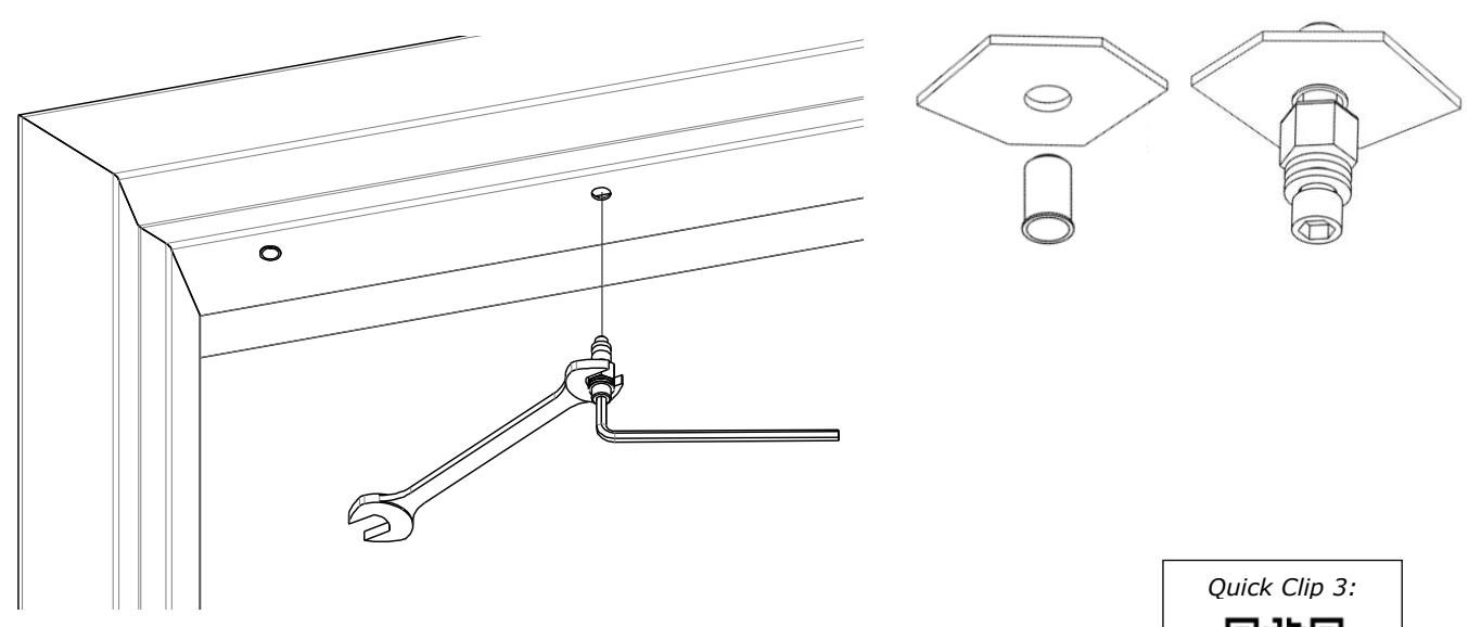
6. Blind Nut Installation:
Use the tool provided to install blind nuts into each 3/8" diameter hole. Hold the collapsing nut with a 1/2" box end wrench. Maintain pressure on the mounting surface, while using a 3/16" hex wrench to tighten the cap screw and collapse the blind nut. Go to Step 8.
Why Use Blind Nuts?
Blind nuts provide a highly secure and tamper resistant system for mounting and are the mounting hardware provided for this unit.
Only use approved included hardware for mounting.

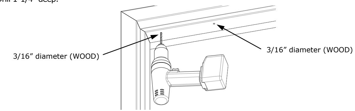
7. Wood Door Frame – Drill Mounting Holes:
Drill two (2) 3/16" diameter holes at bracket-mounting hole marks. Drill 1-1/4" deep.
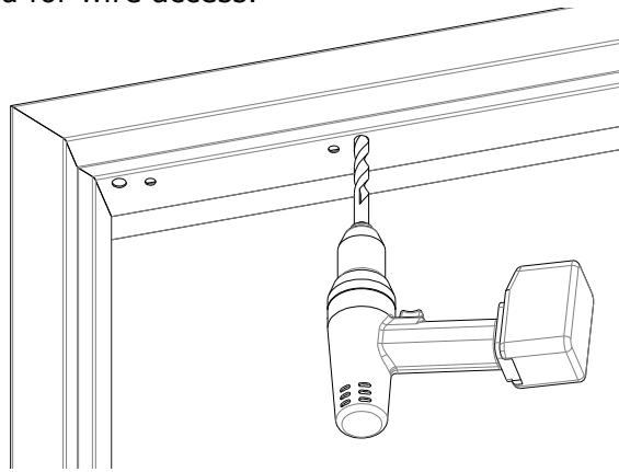
8. Drill Wire Access Holes
Drill wire access holes as needed on one (1) or both sides of the bracket location.
1/2" diameter is recommended for wire access.
9. Install Bracket:
Use a Phillips screwdriver to temporarily install the bracket with spacers against the closed door. Metal Frames: Use two (2) 1/4-20 X 1" Phillips Pan Head Screws and apply included thread lock to screw threads.
Wood Frames: Use two (2) #12 X 1-1/2" Type A, Phillips Pan Head Screws.
Strike Installation
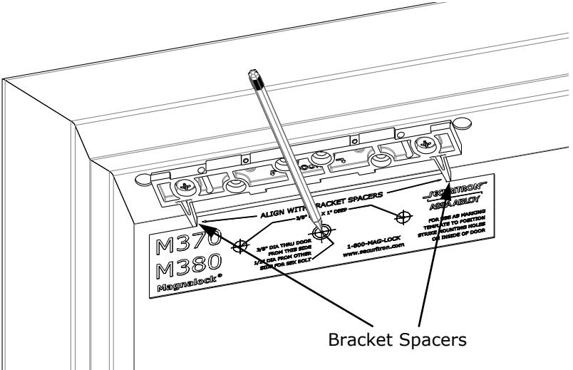
1. Close the door and place the template between the bracket spacers. Mark the strike plate hole locations.
Bracket spacers can now be removed from the bracket.
Quick Clip 4:

Strike Installation
2. From INSIDE the door:
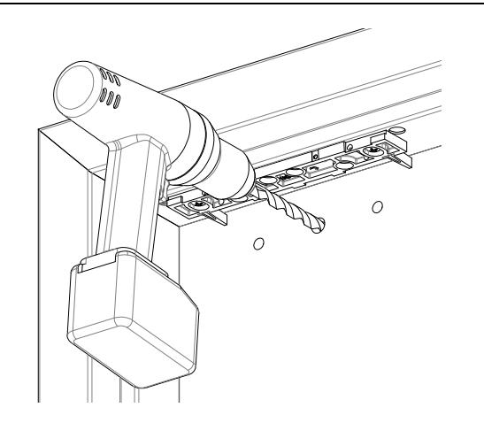
Drill one (1) 3/8" diameter hole for the sex bolt through the door at the strike mounting center mark.
Drill two (2) 3/8" diameter x 1" deep holes at each side mark for the strike alignment roll pins. Do not drill through the door.

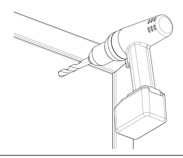
3. From OUTSIDE the door:
For a Hollow Metal Door : Drill out the 3/8" diameter strike mounting hole to 1/2" diameter in the outer wall only . For a Solid Wood Door : Drill out 3/8" diameter strike mounting hole to 1/2" diameter; drill completely through .
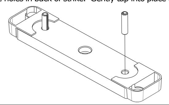
4. Install Roll Pins into Strike Plate:
Remove the two (2) roll pins from the hardware packet. Insert a roll pin into each of the holes in back of strike. Gently tap into place using a hammer.
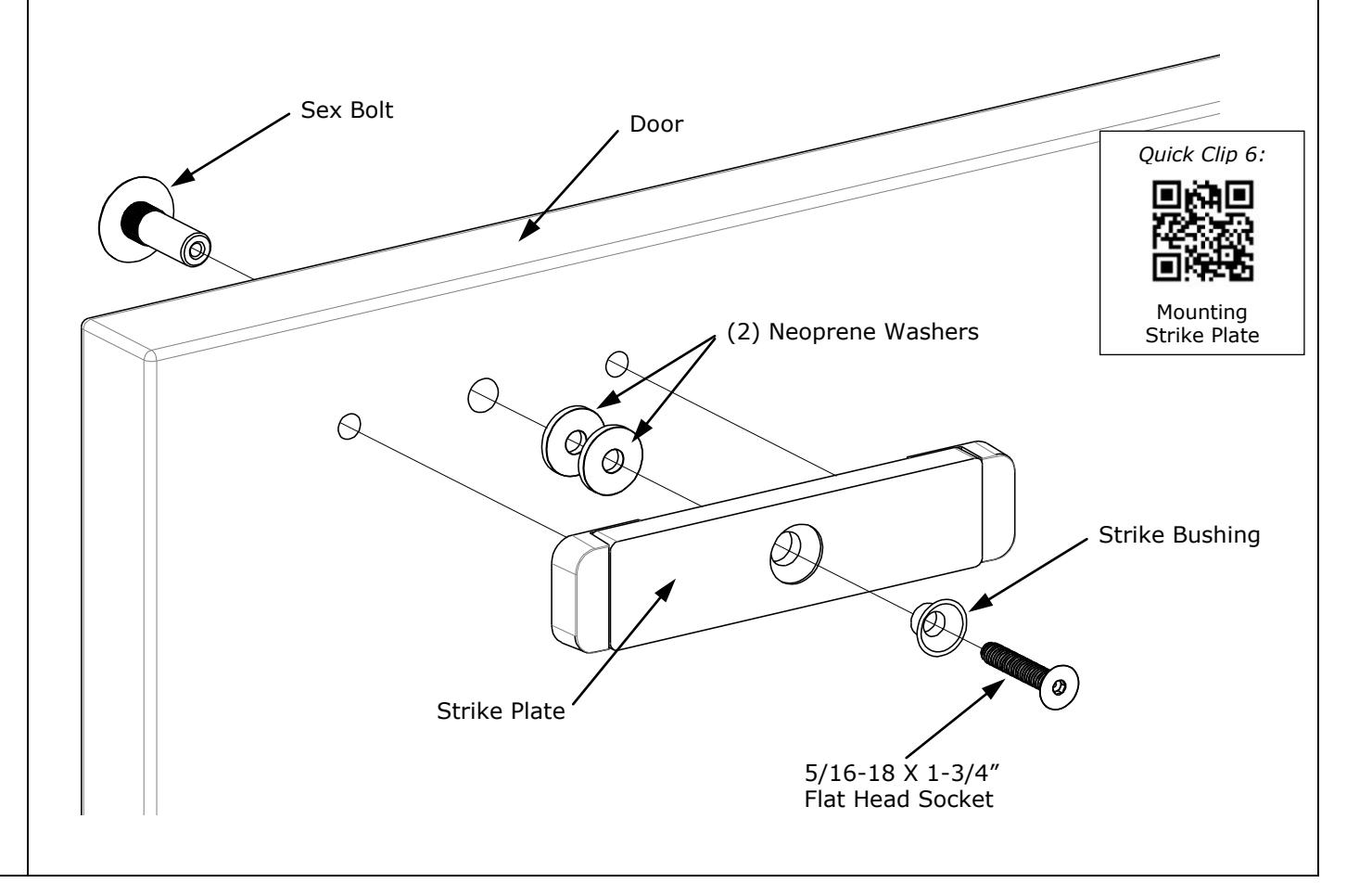
5. Secure Strike Plate to the Door
Apply the included thread lock compound to the 5/16-18 X 1-3/4" flat head socket screw. Pass the 5/16-18 X 1-3/4" flat head socket screw through the strike bushing, strike plate, two (2) neoprene washers, door and into the sex bolt as illustrated.
Use a 3/16" hex wrench to tighten the screw into the sex bolt. (While tightening, use a hammer to gently tap the head of the sex bolt until the head sits flush with the door).
Not Do NOT over-tighten the assembly; the neoprene washers should not be compressed. Allow the strike to rock on the neoprene washers for proper function and optimum holding force.
Adjustments:
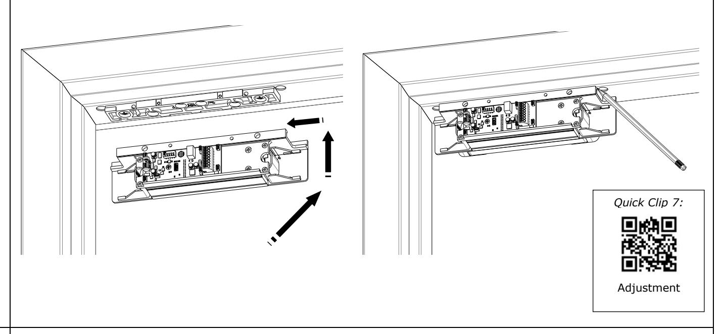
1. Assemble Lock to the Bracket and Adjust:
Loosen the two screws securing the mounting bracket to the door frame so that the bracket can move.
Slide the lock onto the mounting bracket and test fit against the strike plate with the door closed. Slide the lock so that the entire face makes contact with the strike plate.
Mark back edge of mounting bracket at each end and remove the lock from the bracket.
2. Ensure that the mounting bracket aligns with the marks and tighten the mounting screws.
3. Drill Frame for Anchor Screws:
Using the mounting bracket as a template, drill the four remaining holes in the frame for the anchor screws.
Metal Frames: Drill 3/16" diameter holes. Wood Frames: Drill 7/32" diameter holes.
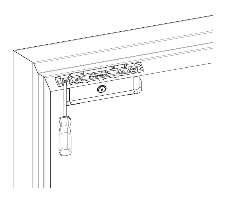
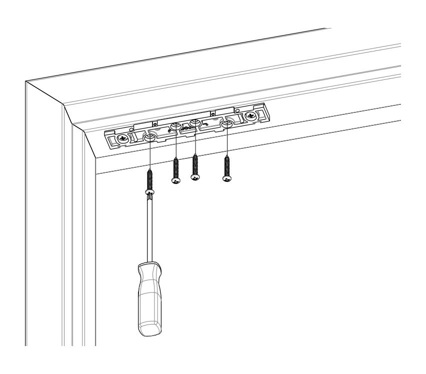
4. Install Anchor Screws:
Using a Phillips screwdriver, install the four (4) anchor screws.
Metal Frames: Use #12 X 1-1/2" Type A, Phillips Pan Head Screws.
Wood Frames: Use #14 X 3" Type A, Pan Head Screws.
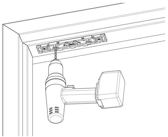
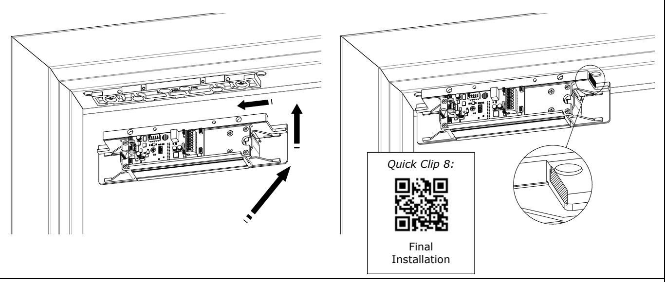
Final Installation:
1. Insert the top of the Magnalock chassis at the end of the mounting bracket. Slide the lock chassis to the center of the bracket.
The edge of the lock chassis must be flush with the end of the mounting bracket when centered (see inset).
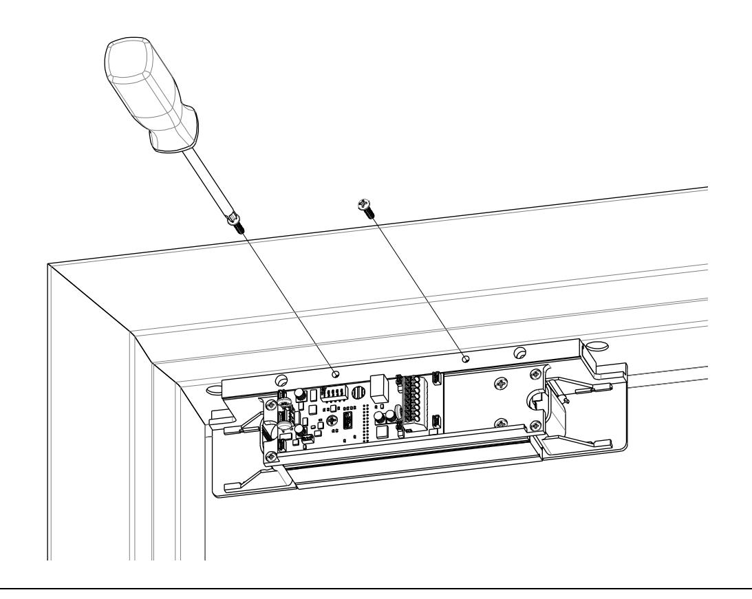
2. Using a Phillips screwdriver, install the two (2) 6-32 X 5/8" Phillips pan head screws to secure the lock chassis to the mounting bracket.
Final Wiring
1. Pull wires/cables through the wire feed-through hole(s) that are drilled in the frame. All connections to the terminal blocks may be made by pressing the locking mechanism, inserting the stripped wire into the terminal recess and releasing to lock the wire in place.
The end user and installer are liable for Fire and Building code compliance.
2. The following diagrams show basic wiring configurations for the Magnalock.
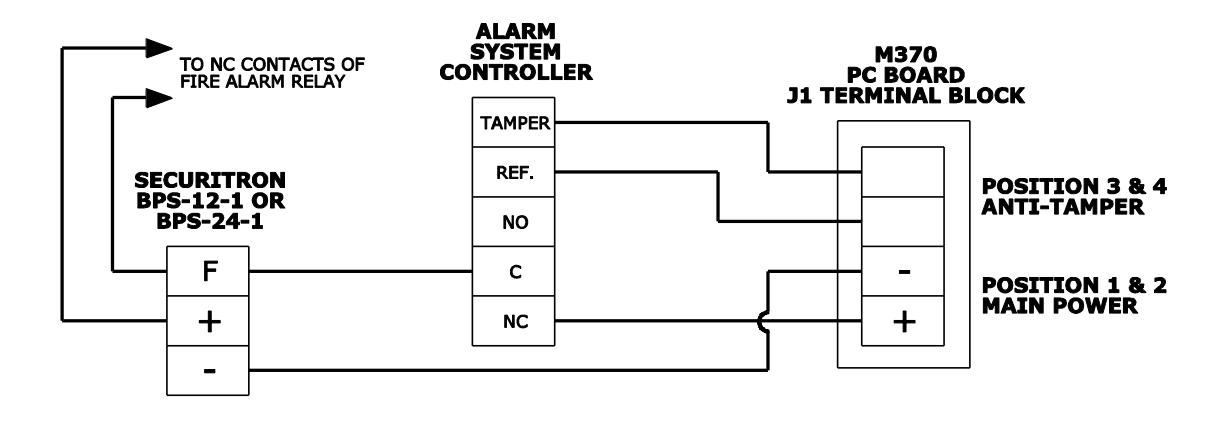
M370
3. After installation and wiring have been completed, re-install the lock cover through the lock chassis using the two (2) Phillips screws removed in the first step.
MAGNALOCK MAINTENANCE
Visual Inspection
Check the rubber washers for elasticity and proper pivoting. Tighten as required.
Check for build-up of debris on the Magnalock and strike armature.
Check for rust on the Magnalock and strike plate armature. Clean as required.
Cleaning Methods
Apply rubbing alcohol onto a clean cloth and thoroughly wipe down the Magnalock and strike plate armature.
Cleaning once a year is recommended.
Clean every three to six months where rusting occurs.
Use a plastic dishwashing scrub pad to aid in the removal of rust.
DO NOT USE PETROLEUM BASED PRODUCTS FOR CLEANING DO NOT USE STEEL WOOL BASED SCRUB PAD OR SANDPAPER
Troubleshooting Guide:
| POSSIBLE ISSUES | TROUBLESHOOTING TIPS | |
|---|---|---|
| No power or low power | Confirm voltage and current at Magnalock to spec | |
|
(See
page 2). |
||
| Check that the DC Power Source is Full Wave Rectified | ||
| (Half wave Rectified or AC power is unacceptable). | ||
| Reduced Holding Force | Check strike plate position and orientation. | |
| Clean surfaces and check for obstructions. | ||
LED Error Codes:
Note: The position 1 switch of DIP switch SW3 must be set to the ON position (LED ENABLED) for error codes to be visible.
| CODE | STATE | SOLUTION |
|---|---|---|
|
SECURE selected color,
on continuously |
Normal Operation with
Door Closed |
System working normally, SECURE selected
color can be selected with position 2 switch of SW3. See page 4. |
|
NON-SECURE selected
color, on continuously |
Normal Operation with
Door Open |
System working normally. |
|
RED/GREEN
continuous flash |
Processor Error |
Check
all connections, if error persists replace unit. |
|
3 Fast Flashes of
SECURE color every 5 seconds |
Magnet Voltage has
dropped below 85% |
Check voltage and current at Magnalock
connections. Check DC Power Source is Full Wave Rectified. |
|
Single Flash Amber
every 5 seconds |
Bond Error –
Left Side |
Check strike plate position and orientation.
Clean surfaces and check for obstructions. |
|
Double Flash Amber
every 5 seconds |
Bond Error –
Right Side |
Check strike plate position and orientation.
Clean surfaces and check for obstructions. |
| Off | LED disabled |
Check voltage and current at Magnalock
connections. Check that LED is enabled with position 1 switch of SW3 is in the OFF position. |
Problems with Installation?
Call Securitron: 1-800-MAGLOCK
For warranty information: visit www.securitron.com/en/site/securitron/About/MagnaCare-Warranty/