Securitron M34R Electromagnetic Locks Operating Manual
Open the original PDF document
View PDF

RECESSED MAGNALOCK MODEL M34R SERIES INSTALLATION AND OPERATING INSTRUCTIONS
1. INTRODUCTION
The Securitron Series of Recessed Magnalocks were designed for installations where concealed, mortise type mounting in the door and frame is desired. The M34R was designed to operate primarily with sliding type doors and are usually installed vertically for proper operation.
The M34R lock is also available with the following features:
The BondSTAT "B" Series, Bond Sensor, monitors the magnetic field. An internal sensor activates a SPDT dry contact relay connection designed for interface to access control and/or alarm systems for reporting the status of the Magnalock. (See Section 5.5.2 )
The DPS "D" Series, Door Position Sensor, is activated by a special magnetic strike armature assembly. The isolated SPDT reed switch, with an internal resettable protection device, is designed for interface to access control and/or alarm system for door status. (See Section 5.5.2 )
2. SPECIFICATIONS
| MODEL | M34R | ||
|---|---|---|---|
| Holding Force | 500 Lbs [227 kg] | ||
| Dimensions: Length | 10.55" [275mm] | ||
| Height | 1.5" [38mm] | ||
| Depth | 1.19" [30mm] | ||
| Dual Voltage | 12/24 Volts DC | ||
| Current: @ 12 VDC | 320mA | ||
| @ 24 VDC | 170mA | ||
| Capacitance: @ 12 VDC | 6.8 mF | ||
| @ 24 VDC | 6.8 mF | ||
| BondSTAT Rating |
Voltage: 30 VDC (Maximum)
Current: 1 Amp (Maximum) |
||
| DPS Rating |
Voltage: 30 VDC (Maximum)
Current: 125 mA (Maximum) |
||
3. PRODUCT OVERVIEW
Upon unpacking this product, an inventory should be made to ensure that all the required components and hardware have been included. Along with these instructions and the installation template, each product should include the following items:
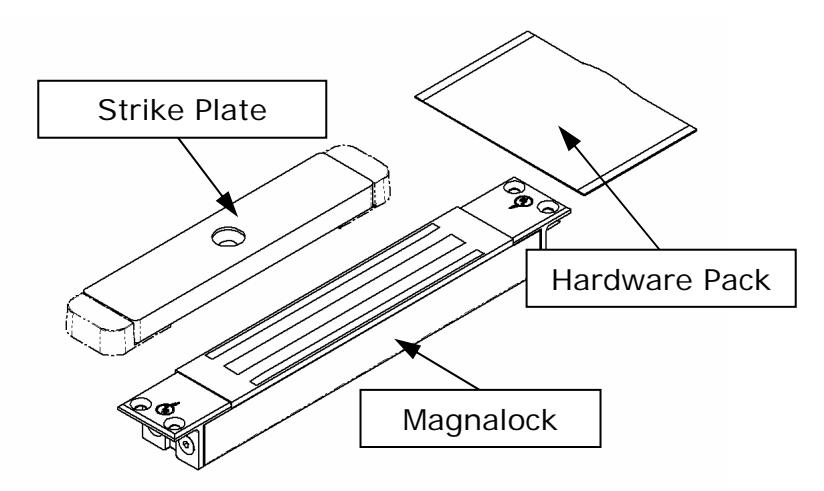
Figure 1 – M34R Series Magnalock
4. RECOMMENDED TOOLS
Router or Saber Saw 1/8" Hex Key (Allen Wrench) - included
Hammer Measuring Instrument (Ruler/Tape Measure)
Chisel Masking Tape
Center Punch Fish Tape or Lead Wire Power Drill Wire Strippers/Cutter
9/64", 13/64", 5/16" and 3/8" Drill Bits Crimp Wire Connectors
5/8" Diameter X 82° Countersink Bit Crimp Tool Phillips and Standard Screwdrivers Multimeter
5. INSTALLATION INSTRUCTIONS
5.1 Pre-Installation Survey
It is recommended that an initial on sight survey be performed. A method of mounting should be determined and an installation plan should be reviewed as follows:
- Physical strength of mounting areas should be strong enough to meet or exceed the holding force of the required Magnalock.
- Placement of the Magnalock wiring and protection from potential damage due to intruders or vandals external attack should be considered during the survey.
- Accessibility should be considered for prevention of any potential safety hazard.
The door and frame areas additionally need to be examined for mortising capabilities, sufficient size and should be free of any internal obstructions.
5.2 Sliding Door
The illustrations in Figure 2 demonstrate a Recessed Magnalock installed in a sliding door. The Magnalock mounts recessed into the door frame and the strike assembly is mounted into the leading edge of the sliding door.
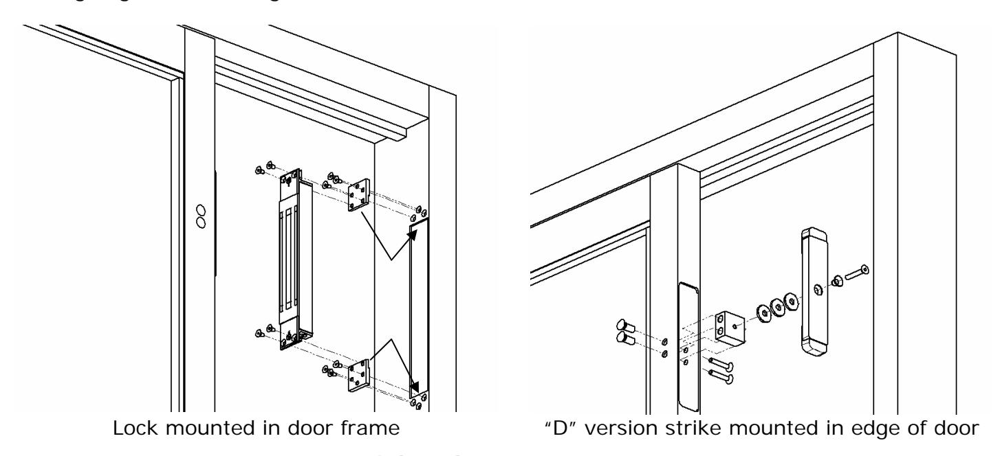
Figure 2 - Sliding door mounting configuration
5.3 Frame and Door Preparation
5.3.1 Frame Preparation
Select a mounting location for the lock and strike assembly as mentioned in Section 5.1 . The following general guideline should be used for consideration during the installation review:
- Read and follow the directions on the template provided which includes drilling and mounting instructions.
- An approximated 2" [51mm] clearance distance should be allowed between the lock (mounting bracket) and the inside corner of the door frame. This will provide adequate access for the mounting locations and for drilling and tool access.
PN# 500-13800 Page 2 Rev. D, 04/11
BEFORE CUTTING OR DRILLING ANY HOLES - ALWAYS CHECK THE STRIKE MOUNTING AREA IN THE EDGE OF THE DOOR FOR OBSTACLES WHEN PLANNING WHERE TO LOCATE THE LOCK. MAKE CERTAIN THAT THE STRIKE MOUNTING AREA DOES NOT HAVE ANY OBSTRUCTIONS (I.E. DOOR ADJUSTMENT SCREWS OR DOOR CLOSER OPERATORS) THAT MIGHT HINDER THE INSTALLATION.
- Horizontally mark the door face and the frame to identify the desired height location of the lock/strike installation.
- Locate and mark the desired vertical centerline position for the lock/strike assembly in the center of the leading edge of the door. Using this door mark as reference, mark the same vertical center location for the lock onto the door frame.
- Using the magnet body mounting information in Section 5.4 and the lock template provided, center the appropriate template into position on the frame and mark the mortise cutout area.
- Using a router, saber saw, or chisel (for wood) cut out the area for the lock mounting. Insert the lock into the frame and mark the bracket locations for the mounting holes.
- Using the drill size information on the template and a power drill, bore the holes required for mounting.
5.3.2 Door Preparation
- Locate the previously marked horizontal and vertical centerlines for the strike assembly on the edge of the door.
- Using the strike assembly mounting information in Section 5.5 and the strike template provided, align the template into position onto the frame and mark the mortise cutout area and the hole locations for the strike mounting block. (Note the different sizes for the cutout – the "D" version of the M34R requires the longer cutout to provide room for the door position actuators at each end of the strike).
- Using a router or saber saw cut out the area for the strike mounting.
- Using the drill size information on the template and a power drill, bore the holes required for mounting.
5.4 Mounting the Magnet Body
The desired cable exit location should be determined prior to installing the magnet body. The lock is symmetrical which allows the cable exit from the top or bottom of the door frame. There are many different techniques for mounting the lock depending on the type or style of doors and frames. The following sections describe installation methods for use on hollow aluminum, steel and wood type doors and frames.
5.4.1 Hollow Metal Door Frames
Prepare the door frame in accordance with Section 5.3.1 .
Place the lock body into the cutout area to ensure proper fit. As necessary, perform any filing or cutting necessary to ensure the mortised fit. Ensure all necessary holes required to mount the magnet body and flush mount brackets into place as indicated on the template have been provided. Install the lock using a hex wrench, the listed mounting screws and the flush mount brackets as shown in Figures 3 and 4 below. The adaption to variation in frame material thicknesses can be obtained by flipping the orientation of the flush mount brackets. Shim plates are also provided which may be used in conjunction with the flush mount brackets to create the desired exposed height of the lock and/or to compensate for the various material thicknesses of door frames. It is recommended that the magnet face protrude approximately 1/16" [1.5mm] beyond the surface of the frame. Both Figures 3 and 4 show a shim plate between the lock mounting bracket and the flush mount bracket in order to raise the magnet above the frame surface.
| Flat Head Screws | M34R |
|---|---|
| Unified | 10-32UNC x 3/8" |
| Metric | M5-0.8 x 10mm |
PN# 500-13800 Page 3 Rev. D, 04/11
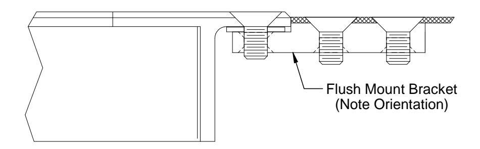
Figure 3 - Flush mount bracket mounting (thin wall frame)
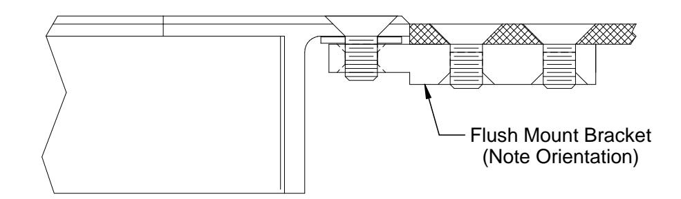
Figure 4 - Flush mount bracket mounting (thick wall frame)
APPLY THE PROVIDED THREAD LOCKING COMPOUND TO ALL MOUNTING SCREW THREADS.
5.4.2 Solid Wood Door Frames
Prepare the door frame in accordance with Section 5.3.1 .
Place the lock body into the cutout area to ensure proper fit. As necessary, perform any filing or chiseling necessary to ensure the mortised fit. Ensure all necessary holes required to mount the magnet body into place as indicated on the template have been provided. The depth of the mortise cut out is important depending on the lock model being installed. The minimum depth of the cut out is noted in Figure 5 below and includes enough distance for the required recess depth of 1/16" [1.5mm] for the mounting brackets. Install the lock using the wood mounting screws as shown in Figure 5 .
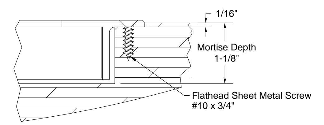
Figure 5 - Wood frame lock bracket mounting
5.5 Mounting the Strike Assembly
5.5.1 Hollow Metal Door
Prepare the door in accordance with Section 5.3.2 .
Using the provided template and Figure 2 for reference, install the strike mounting block into the edge of the door using a hex wrench and the provided mounting screws and sex bolts. Assemble the strike to the mounting block using the strike mounting screw, plastic strike bushing and one, two or three of the rubber washers to complete the installation.
APPLY THE PROVIDED THREAD LOCKING COMPOUND TO ALL MOUNTING SCREW AND SEX BOLT THREADS.
PN# 500-13800 Page 4 Rev. D, 04/11
5.5.2 Lock/Strike Installation for "B" and "D" M34R Locks
IMPORTANT!
PLEASE READ AND APPLY THIS INFORMATION WHEN ALIGNING/INSTALLING THE LOCK AND STRIKE. THE ALIGNMENT TOLERANCES INDICATED FOR THE M34R LOCK MODEL ARE CONSIDERED CRITICAL FOR THE PROPER OPERATION OF BOTH THE MAGNETIC BOND SENSING (MBS) AND DOOR POSITION SENSING (DPS) SYSTEMS!
SENSOR RANGES (PHYSICAL POSITIONING):
The BondSTAT "B" and DPS "D" Magnalock " Secure Zone " sensing range for the M34R lock model is as follows:
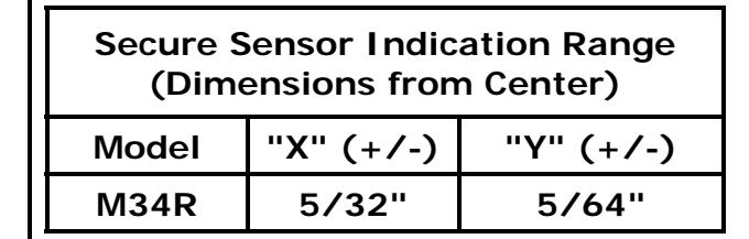
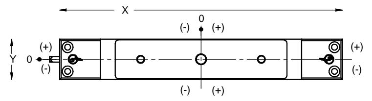
Table A
Figure 6
(The Figure 6 illustration is a visual reference to the sensing range outlined in Table A ).
6. ELECTRICAL INSTALLATION
6.1 General Characteristics
The Magnalock is a low current load device using specialized internal circuitry. The normal characteristic of an inductive load, such as inductive kick-back, is not present. See Section 2 for more information.
6.2 Electrical Standards
DC voltage, full-wave rectified, must be provided for proper operation of the Magnalocks. The red wire receives +12VDC or +24VDC, and the black wire, 0 Volts (negative). If the lock is connected with reverse polarity, it will not operate. The M34R Series Magnalocks are auto sensing dual voltage locks. The Magnalock circuit design will automatically select the proper operational conditions for the applied voltage. See Section 2 for more information.
6.3 Poor Release Characteristics
The M34R Magnalock is designed with quick release circuitry. Wiring errors may cause a Magnalock to release slowly. Figure 7 illustrates a parallel installation of a resistive load (correct). Figure 8 illustrates a parallel reverse diode (incorrect).

Figure 7 Figure 8
6.4 Sensor Ranges (ELECTRICAL)
The M34R "B" version monitoring system is also voltage sensitive. The specified voltage ranges must be properly applied. Refer to Section 2 for the recommended operating voltage ranges.
6.5 Electrical Wiring
The following diagrams, Figures 9 , 10 , 11 and 12 represent the proper electrical wiring connections required for the M34R Magnalock Standard, and for the BondSTAT "B", DPS "D" and "BD" versions.
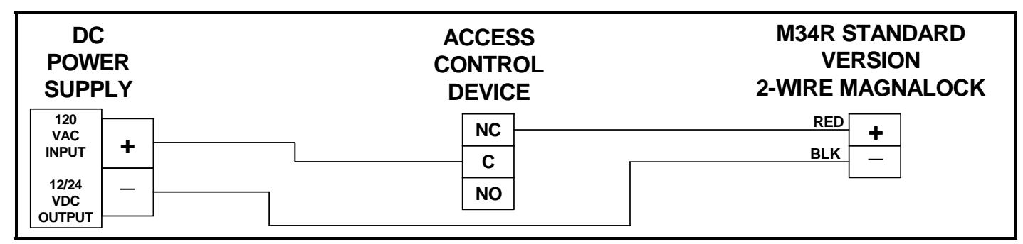
Figure 9
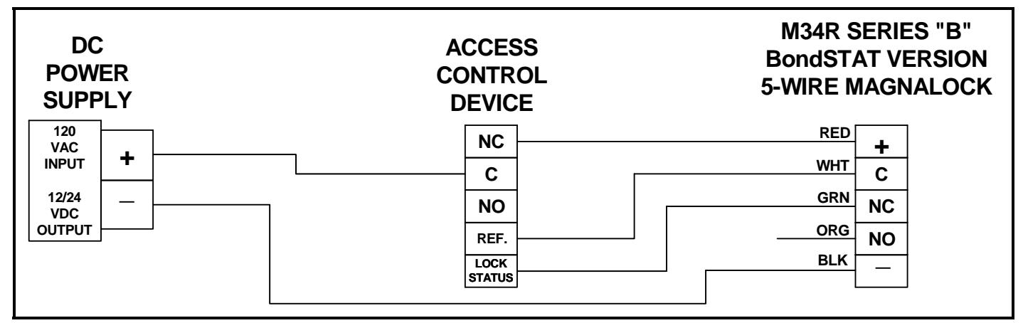
Figure 10

Figure 11

Figure 12
6.6 BondSTAT Sensor status wiring description
- The green and white wires supply electrical connection when the lock is ON and secure.
- The orange and white wires supply electrical connection when the lock OFF or unsecure.
6.7 DPS – Door Position Sensor status wiring description
- The blue and yellow wires supply electrical connection when the door condition is closed.
- The brown and yellow wires supply electrical connection when the door condition is open.
6.8 Emergency Release
Magnalocks are often wired into a system for quick release in case of emergency. Manual switching or automatic triggering from a fire alarm system is practical. It is the user's responsibility to correctly hookup the Magnalock according to the instructions. It is recommended to use a switch or relay to perform break of power. Securitron power supplies have terminals for the interconnection of such emergency release switches.
THE END USER & INSTALLER ARE LIABLE FOR FIRE & BUILDING CODES COMPLIANCE
7. MAGNALOCK MAINTENANCE
7.1 Visual Inspection
- Check the rubber washers for elasticity and proper pivoting. Tighten as required.
- Check for build-up of debris on the Magnalock and strike armature. Clean as required.
- Check for rust on the Magnalock and strike assembly. Clean as required.
7.2 Cleaning Methods
- Cleaning once a year is recommended.
- Clean every six months where minor rusting occurs.
- Clean every three months if rust conditions are severe.
- Use a plastic dishwashing scrub pad to aid in the removal of rust.
DO NOT USE PETROLEUM BASED PRODUCTS FOR CLEANING DO NOT USE STEEL WOOL BASED SCRUB PAD OR SANDPAPER
7.2.1 Indoor Applications
Apply rubbing alcohol onto a clean cloth and thoroughly wipe down the Magnalock and strike plate armature.
7.2.2 Outdoor Applications
Apply a silicone based cleaner/lubricant onto a clean cloth and thoroughly wipe down Magnalock and strike plate armature.
Example: Super Lube® Aerosol with SYNCOLON® (PTFE)
Part No.: 31040 ~ 6oz. / 31110 ~ 11 oz. / 32015 ~ 14 oz. Phone: (631) 567-5300 / Website: www.super-lube.com
8. MAGNACARE LIFETIME REPLACEMENT WARRANTY
For warranty information visit www.securitron.com/en/site/securitron/About/MagnaCare-Warranty/
PATENTS
The Securitron Magnalock is listed under U.S. patent #4,516,114 and 4,682,801. Additional patents pending.
PN# 500-13800 Page 7 Rev. D, 04/11
APPENDIX A Troubleshooting
| Problem | Lock Does Not Generate a Magnetic Field | Points of Reference | ||
|---|---|---|---|---|
| Solution | Check for specified voltage at Magnalock | Section 2 | ||
| Check for specified current draw at Magnalock | Section 2 | |||
| Problem | Reduced Holding Force | Points of Reference | ||
| Check DC power source is Full-Wave Rectified | ||||
| (Half-wave Rectifier or AC Power unacceptable) | Section 6.2 | |||
| Check for specified voltage at Magnalock | Section 2 | |||
| Solution | Check for specified current draw at Magnalock | Section 2 | ||
| Check strike mounting for proper installation | Sections 5.2-5.5 | |||
|
Check the Magnalock and strike for obstructions
and that contact surfaces are properly cleaned |
Section 8 | |||
| Problem | BondSTAT Does Not Report Secure | Points of Reference | ||
| Check for specified voltage at Magnalock | Section 2 | |||
| Check for specified current draw at Magnalock | Section 2 | |||
| Solution |
Check strike mounting for proper alignment and
pivoting for proper closure to Magnalock |
Table A / Section 5.5.2 | ||
|
Check the Magnalock and strike for obstructions
and that contact surfaces are properly cleaned |
Section 7 | |||
| Problem | DPS Does Not Report Door Status | Points of Reference | ||
|
Check strike mounting for proper alignment
Check for proper door closure |
Table A / Section 5.5.2
Section 7 |
|||
| Solution | Check for proper voltage/current on switch | Section 2 | ||
| Check resettable protection device | Section 1 | |||
| Problem | The Magnalock Does Not Release | Points of Reference | ||
| Make sure no voltage is present at Magnalock | Section 2 | |||
| Solution |
Make sure the Magnalock is not drawing current
Check if the strike is sticky and hard to release |
Section 2
Section 7 |
||
|
Check the Magnalock and strike for obstructions
and that contact surfaces are properly cleaned |
Section 7 | |||
|
Problem
Solution |
The Magnalock is Dirty or Rusty
Improper cleaning – Maintenance Equipment |
Points of Reference
Section 7 |
||
| Problem |
Electronic Noise Interference with
Access Control System |
Points of Reference | ||
IF PROBLEMS PERSIST CALL SECURITRON TOLL FREE (800) MAG-LOCK (800) 624-5625
PN# 500-13800 Page 8 Rev. D, 04/11
Appendix B
Wire Gauge Factoring
1.1 Remote Power Supply
- The Magnalock requires adequate voltage and current for proper operation.
- Resistance is created by the length and gauge (size) of the wire being used.
- An accurate estimated distance from the power supply to the opening is crucial.
- For superior operation the correct size gauge wire must be used.
- The devices used operate the best with the least amount of resistance on the source.
- Using the correct gauge wires protects against large voltage and current (load) losses.
- The gauge is determined by the wire distance, voltage and current of all devices.
1.2 Determining Wire Gauge
- Follow Example A (12VDC system) and Example B (24VDC system) below.
- Use Tables 1 and Table 2 to choose the correct wire gauge for the application.
1.2.1 Example A: (12VDC system)
| Devices Used | Amps (12VDC) | Progressive Totals | ||
|---|---|---|---|---|
| M34R Magnalock | 0.320 | 0.320 | ||
| DK-26 Access | 0.160 | 0.480 | ||
| XMS Motion | 0.050 | 0.530 | ||
| EEB2 Timer | 0.025 | 0.555 | ||
| Total Current Rounded Up (Table 1) | 0.600A | |||
Using Table 1 (12VDC) Find: - Current Draw .600 Amps
- Wire Distance 200 Feet (One-Way)
Solution: 18 Gauge is indicated for proper installation
1.2.2 Example B: (24VDC system)
| Devices Used | 24VDC Amps | Progressive Totals | |
|---|---|---|---|
| M34R Magnalock | 0.170 | 0.170 | |
| DK-11 Access | 0.070 | 0.240 | |
| XDT-24 Delay | 0.050 | 0.290 | |
| Total Current Rounded Up (Table 2) | 0.300A | ||
Using Table 2 (24VDC) Find: - Current Draw .300 Amps
- Wire Distance 1000 Feet (One-Way)
Solution: 16 Gauge is indicated for proper installation
PN# 500-13800 Page 9 Rev. D, 04/11
TO SOLVE: INTERSECT ROW (Current) and INTERSECTING COLUMN (Wire Distance)
| 1.0A |
20
Gauge |
18
Gauge |
16
Gauge |
14
Gauge |
14
Gauge |
12
Gauge |
10
Gauge |
10
Gauge |
8
Gauge |
|
|---|---|---|---|---|---|---|---|---|---|---|
| С | .800A |
22
Gauge |
18
Gauge |
18
Gauge |
16
Gauge |
14
Gauge |
12
Gauge |
10
Gauge |
10
Gauge |
8
Gauge |
|
U
R R |
.600A |
22
Gauge |
20
Gauge |
18
Gauge |
18
Gauge |
16
Gauge |
14
Gauge |
14
Gauge |
12
Gauge |
10
Gauge |
|
E
N T |
.400A |
22
Gauge |
22
Gauge |
20
Gauge |
18
Gauge |
18
Gauge |
16
Gauge |
14
Gauge |
14
Gauge |
12
Gauge |
| .300A |
24
Gauge |
22
Gauge |
22
Gauge |
20
Gauge |
18
Gauge |
18
Gauge |
16
Gauge |
14
Gauge |
14
Gauge |
|
| .200A |
24
Gauge |
22
Gauge |
22
Gauge |
22
Gauge |
20
Gauge |
18
Gauge |
18
Gauge |
16
Gauge |
14
Gauge |
|
| 12VDC |
50′
[15m] |
100′
[30m] |
150′
[46m] |
200′
[61m] |
300′
[91m] |
400′
[122m] |
500′
[152m] |
750′
[229m] |
1000′
[305m] |
|
| W | IRE DIS | TANCE | ||||||||
Table 1
| 1.0A |
22
Gauge |
20
Gauge |
20
Gauge |
18
Gauge |
16
Gauge |
14
Gauge |
14
Gauge |
12
Gauge |
10
Gauge |
|
|---|---|---|---|---|---|---|---|---|---|---|
| .800A |
22
Gauge |
22
Gauge |
20
Gauge |
18
Gauge |
18
Gauge |
16
Gauge |
14
Gauge |
14
Gauge |
12
Gauge |
|
|
C
U R R |
.600A |
24
Gauge |
22
Gauge |
22
Gauge |
20
Gauge |
18
Gauge |
18
Gauge |
16
Gauge |
14
Gauge |
14
Gauge |
|
E
N T |
.400A |
24
Gauge |
22
Gauge |
22
Gauge |
22
Gauge |
20
Gauge |
18
Gauge |
18
Gauge |
16
Gauge |
14
Gauge |
| .300A |
24
Gauge |
24
Gauge |
22
Gauge |
22
Gauge |
22
Gauge |
20
Gauge |
20
Gauge |
18
Gauge |
16
Gauge |
|
| .200A |
24
Gauge |
24
Gauge |
24
Gauge |
22
Gauge |
22
Gauge |
22
Gauge |
20
Gauge |
20
Gauge |
18
Gauge |
|
| 24VDC |
50′
[15m] |
100′
[30m] |
150′
[46m] |
200′
[61m] |
300′
[91m] |
400′
[122m] |
500′
[152m] |
750′
[229m] |
1000′
[305m] |
|
| WIRE DISTANCE | ||||||||||
Table 2
- The Wire Distance indicated on the table above represents a 2-wire "One-Way" length from the power supply source to entryway installation area.
- The Gauge values specified on the table above represent a 2-wire "Round Trip" length from the power supply source to entryway installation and returning back to the power supply source.
IMPORTANT
THE 200' [61m] WIRE RUN IN EACH TABLE FACTORS A 400' [122m] ROUND TRIP
PN# 500-13800 Rev. D, 04/11