Securitron M32, M62, M82B Electromagnetic Locks Operating Manual
Open the original PDF document
View PDFSecuritron® M32 | M62 | M82 Magnalocks
Installation & Operating Instructions
Introduction
The Securitron Magnalock® family is state of the art in electromagnetic locking, and includes operational electrical characteristics and mounting configuration options addressed in this document.
The BondSTAT "B" Magnalock Series, Bond Sensor, monitors the magnetic field. An internal sensor activates a single pole double throw (SPDT) dry-contact relay connection designed for interface with access control and/or alarm systems, which reports the status of the Magnalock.
The DPS "D" Magnalock Series, Door Position Sensor, is activated by a special magnetic strike armature assembly. This isolated SPDT reed switch, with an internal resettable protection device, is designed to interface with an access control and/or alarm system to monitor door status.
Product Components
A Magnalock
E Funnel Bushing
B Sex Bolt
F Roll Pin
C Roll Pins (2x)
Bushings (2x)
D Strike Plate
G 5/16-18 Screw
H Rubber Washers
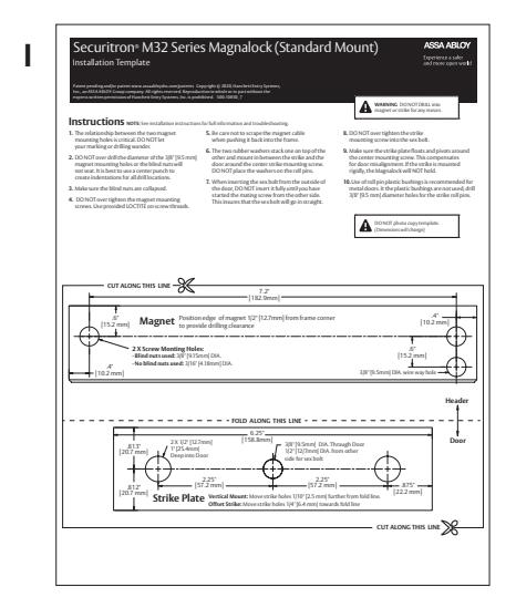
I Magnalock Installation Template
Diagram 1 Product Components A C D B
Recommended Tools
- Power Drill
- Hammer
- Wire Strippers/ Cutter
- 1/8", 3/8", 1/2" Drill Bits
- Center Punch
- Crimp Wire Connectors
- Masking Tape
- Crimp Tool
- 3/16" Hex Key (Allen Wrench)
- Fish Tape or Lead Wire
- Multimeter
- 1/2" Open end or Crescent Wrench

Specifications
| M32 | M62 | M82 | ||||
|---|---|---|---|---|---|---|
| Holding Force | 600 lbs [272 kg] | 1200 lbs [544 kg] | 1800 lbs [816 kg] | |||
| Length | 8" [203 mm] | 8" [203 mm] | 12" [305 mm] | |||
| Height | 1.88" [48 mm] | 3" [76 mm] | 3" [76 mm] | |||
| Depth | 1.6" [41 mm] | 1.75" [44 mm] | 1.75" [44 mm] | |||
| Current at 12 VDC | 300 mA | 250 mA | 350 mA | |||
| Current at 24 VDC | 150 mA | 150 mA | 200 mA | |||
| Capacitance at 12 VDC | 6.8 mF | 44 mF | 44 mF | |||
| Capacitance at 24 VDC | 6.8 mF | 11 mF | 11 mF | |||
| Dual Voltage | 12/24 Volts DC | |||||
| BondSTAT Rating (voltage) | 30 VDC (Maximum) ~ Current 1 Amp (Maximum) | |||||
| DPS Rating (voltage) | 30 VDC (Maximum) ~ Current 125 mA (Maximum) | |||||
Perform a Pre-Installation Survey
NOTE: Additional brackets may be needed for proper installation. Specialized brackets are available through Securitron and its many product distributors.
-
1
PERFORM an initial on-site survey to determine a method of mounting and to review the installation plan, taking the following into consideration:
- Physical strength of mounting areas should be strong enough to meet or exceed the holding force of the required Magnalock.
- Placement of the Magnalock wiring and protection from potential damage due to intruders or vandal's external attack.
- Accessibility for prevention of potential safety hazards.
Diagram 2 Typical Magnalock Installation on an Out-Swinging Door
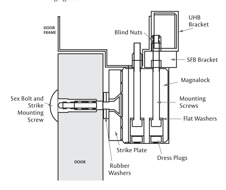
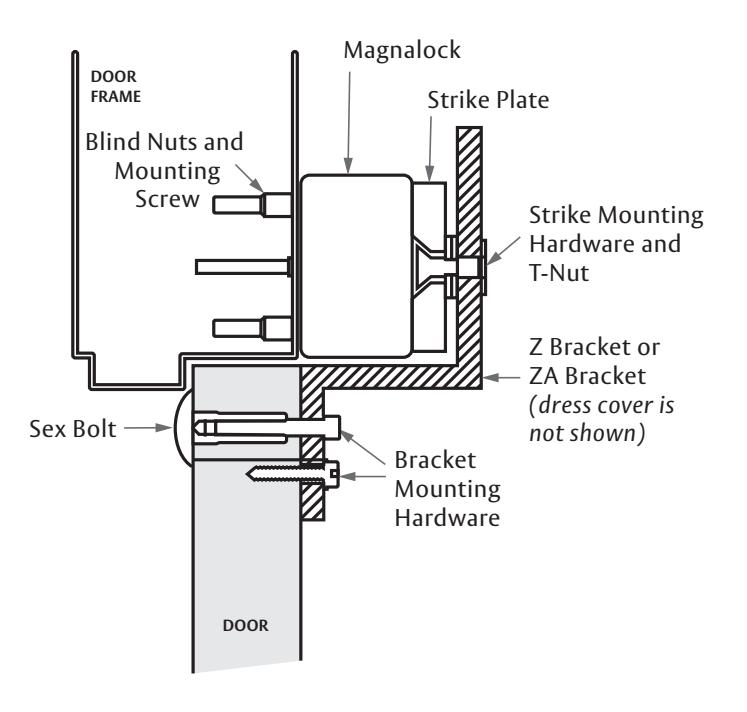
Diagram 3 Typical Magnalock Installation on an In-Swinging Door
Attach the Template and Mark the Drill Holes
-
SELECT a mounting location for the Magnalock and strike assembly.
- NOTE: The edge of the template should be about 1" [25.4 mm] from the latch side of the door to allow proper access at the mounting locations for drilling and tool access.
-
2
ATTACH the template to the door and frame (as shown in Diagram 4).
- IF Installing a strike plate horizontally, THEN ENSURE the top edge of the strike will be approximately 1/8" [3.2 mm] below the door frame stop.
- IF the strike and magnet are to be mounted VERTICALLY, THEN INCREASE the clearance between the strike and frame to 3/16" [4.8 mm].
- 3 WHEN the template is attached, THEN MARK the location of all holes to be drilled using a center punch.
Diagram 4 Attaching the Template TOP OF RAME TOP OF RAME DOOR DOOR FRAME DOOR
Drill Holes for the Lock Body and Strike Plate
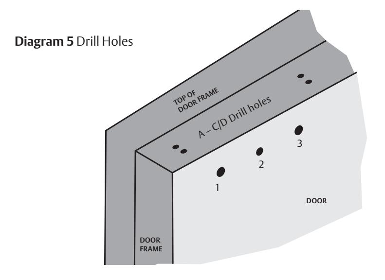
- 1 DRILL Holes #1 and #3 (see Diagram 5) with 3/8" [9.5 mm] diameter without bushings OR 1/2" [12.7 mm] diameter with bushings, and 1" deep into door.
- 2 DRILL Hole #2 (see Diagram 5) with 3/8" [9.5 mm] diameter thru the door, and 1/2" [12.7 mm] diameter from other side for sex bolt.
- 3 DRILL holes per template, in door frame, 3/8" [9.5 mm] diameter for the installation of the lock body blind nuts. OR 3/16" [5 mm] diameter without blind nuts. NOTES: Use a pilot hole, then drill to final size for an accurate hole diameter and placement.
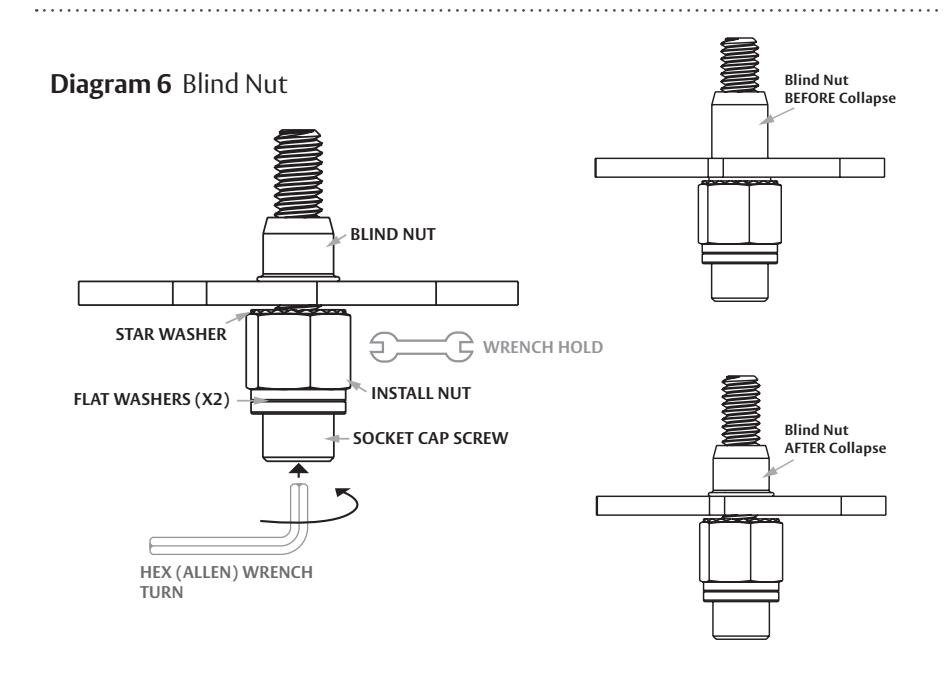
- 4 INSTALL the Blind Nuts (see Diagram 6).
- 5 INSERT the assembled blind nut and installation tool into a 3/8" [9.5 mm] mounting hole.
- 6 HOLD the install nut using a 1/2" [13 mm] box-end wrench and, at the same time, COLLAPSE the blind nut using a 3/16" [5 mm] hex wrench to turn the socket cap screw. NOTE: The collapsing tool is reusable for several blind nut installations.
- 7 REMOVE the collapsing tool when finished. NOTE: Once installed, the blind nuts leave a threaded insert that will accept the machine screws provided in the hardware pack.
- 8 VERIFY that the blind nut is properly collapsed.
Install the Strike Plate
- 1 Using a hammer, TAP the roll pins into the strike plate until seated. Protect face of strike to prevent damage. (see Diagram 9) .
- 2 INSERT the 5/16-18 bolt through the funnel bushing and strike plate (see Diagram 10) .
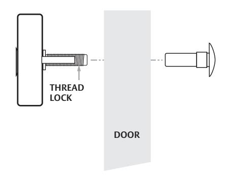
- 3 APPLY thread lock to the 5/16-18 bolt threads (see Diagram 12) .
- 4 INSTALL 2 or 3 rubber washers on the 5/16-18 bolt.
- 5 INSTALL the roll pin bushings into the door (see Diagram 11) .
-
6
From the outside of the door, gently TAP the sex bolt into place.
- NOTE: The strike plate is secured to the door via the supplied sex bolt.
-
7
INSTALL the strike by aligning it with the sex bolt and roll pin bushing and then tightening the center screw
(see Diagram 12)
.
- NOTE: The center screw should not be over tightened; strike should float.
Diagram 9 Seating the Roll Pins
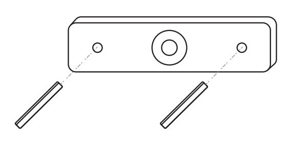
Diagram 10 Install the Bolt through funnel in Strike Plate
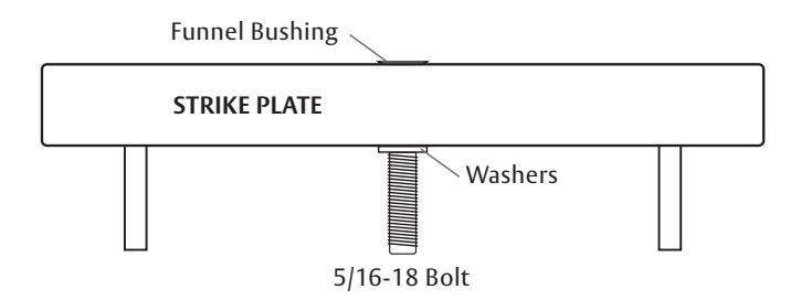
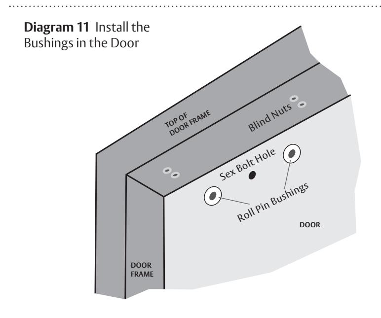
Diagram 12 Tap Sex Bolt into door (outside). Align sex bolt with roll pin bushing.
Install the Magnalock
- 1 PULL the lock wire into frame and to desired location.
- 2 APPLY thread lock to mounting screws.
- 3 MOUNT lock body to frame using supplied hardware (see Diagram 13) .
- 4 INSERT the tamper finish caps into the mounting screw holes (see Diagram 13) .
- 5 ENSURE the Magnalock and strike plate are in proper alignment (see Diagram 14) . NOTE: When installing the Magnalock and strike plate, each should be in proper alignment to the other (see Diagram 14) . This is considered critical for the operation of both the BondSTAT and DPS. However, there are alignment tolerances, see table in Diagram 14 , for each model of Magnalock, but these should be viewed as the
extreme— the installation desire is always total alignment.

CAUTION The Magnalock and strike plate must be in proper alignment or the BondSTAT and DPS functions will not operate correctly
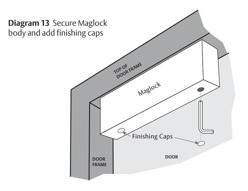
Diagram 14 Maglock and Strike Plate Alignment
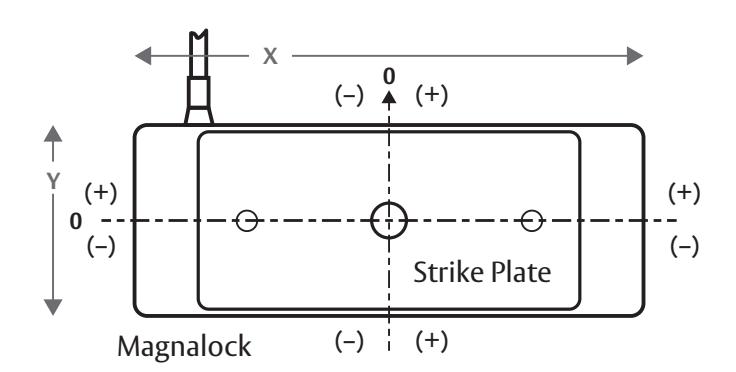
Alignment Tolerances
| MODEL |
X-Coordinate
Alignment (+/–) |
Y-Coordinate
Alignment (+/–) |
|---|---|---|
| M32 B/D | 9/32" | 1/8" |
| M62 B/D | 5/16" | 1/8" |
| M82 B/D | 9/16" | 1/8" |
Wiring

WARNING: A shock hazard may occur if the Magnalock is operated from a DC power supply that is connected to earth ground or not isolated.

CAUTION: The Magnalock must be operated from DC power supply of appropriate capacity and voltage. The DC output of the power supply must not be connected to earth ground but must be isolated, or possible damage to the product could result.
Reference Diagrams 15-18 for wiring by model.
NOTE: In order to confirm that the DC outputs of a power supply are isolated, it can be checked with an ohmmeter between earth ground and +V, and then between earth and 0V (negative). There should not be continuity.
BondSTAT "B" Version
- GREEN and WHITE wires supply electrical connection when the lock is ON and SECURE.
- ORANGE and WHITE wires supply electrical connection when the lock OFF or UNSECURE.
DPS "D" Version
- BLUE and YELLOW wires supply electrical connection when the door condition is CLOSED.
- BROWN and YELLOW wires supply electrical connection when the door condition is OPEN.
Diagram 15 Typical Magnalock Connections
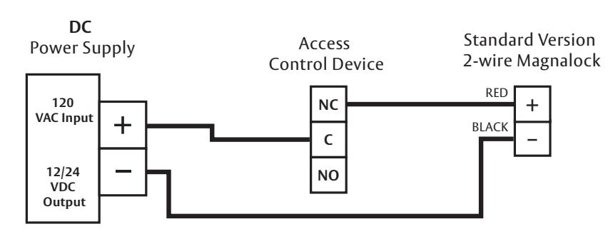
Diagram 16 Connections for BondSTAT "B" Version (5 wires)
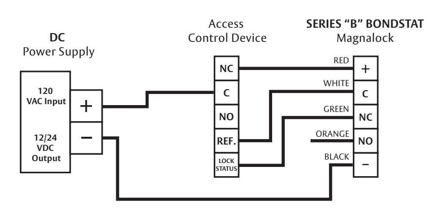
Diagram 17 Connections for DPS "D" Version (5 wires)
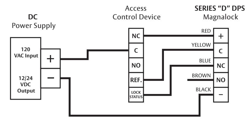
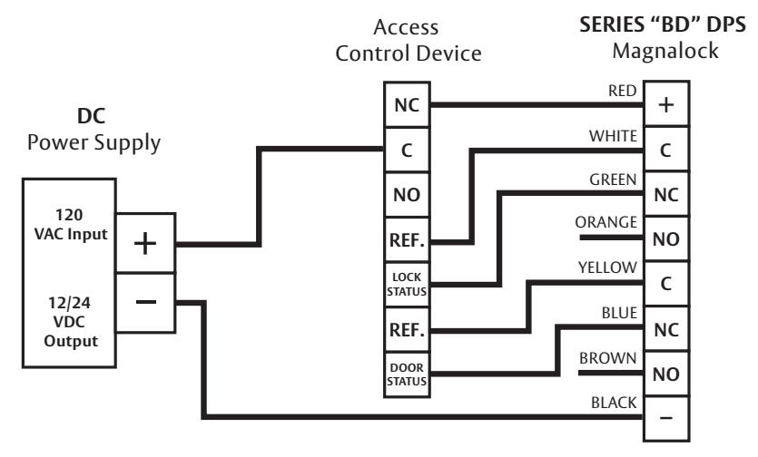
Diagram 18 Connections for "BD" Version (8 wires)
BondStat Double Door Status
When two Magnalocks are used for double door installation, the BondSTAT contacts should be wired in series for proper reporting.
CONNECT the GREEN wire of one lock to the WHITE wire of the other (see Diagram 19).
DPS Double Door Status
When two Magnalocks are used for double door installation, the DPS contacts should be wired in series for proper reporting.
CONNECT the BLUE wire of one lock to the YELLOW wire of the other (see Diagram 20).
Diagram 19 Connections

Diagram 20 DPS Connections

Wire for Emergency Release
- Magnalocks are often wired into a system for quick release in case of emergency.
- Manual switching or automatic triggering from a fire alarm system is practical.
- It is the user's responsibility to correctly hookup the Magnalock according to the instructions.
- Securitron power supplies have terminals for connecting emergency release switches.
- USE a switch or relay to perform break of power.
Determining Wire Gauge
The Magnalock requires adequate voltage and current for proper operation. Resistance is created by the length and gauge (size) of the wire being used. An accurate estimated distance from the power supply to the opening is crucial. For superior operation the correct size gauge wire must be used—the devices used operate optimally with the least amount of resistance on the source. Using the correct gauge wires protects against large voltage and current (load) losses. The gauge is determined by the wire distance, voltage and current of all devices.
- 1 CALCULATE total current for either a 12 VDC system or a 24 VDC system as required. Use Tables 1 or 2 .
- 2 Using the value obtained in Step 1, DETERMINE the proper wire gauge and length using Tables 3 or 4 .
Table 1 12 VDC System Current Used
| Device | Amps (12 VDC) | Progressive Totals | ||
|---|---|---|---|---|
| Securitron M62 Magnalock | .25 | .25 | ||
| Securitron DK-26 Access | .16 | .41 | ||
| Securitron XMS Motion | .05 | .46 | ||
| Securitron EEB2 Timer | .485 | |||
| Total Current (Rounded Up) | .6 A | |||
Table 2 24 VDC System Current Used
| Device | Amps (12 VDC) | Progressive Totals | |
|---|---|---|---|
| Securitron M82 Magnalock | .2 | .2 | |
| Securitron TSB Touch Bar | .025 | .225 | |
| Securitron DK-11 Access | .07 | .295 | |
| Securitron XDT-24 Delay | .345 | ||
| Securitron MK Bypass/Reset | .365 | ||
| Total Current (Rounded Up) | .4 A | ||
Table 3 12 VDC Wire Gauge and Length
| Current | Gauge | ||||||||
|---|---|---|---|---|---|---|---|---|---|
| 1 A | 20 | 18 | 16 | 14 | 14 | 12 | 10 | 10 | 8 |
| .8 A | 22 | 18 | 18 | 16 | 14 | 12 | 10 | 10 | 8 |
| .6 A | 22 | 20 | 18 | 18 | 16 | 14 | 14 | 12 | 10 |
| .4 A | 22 | 22 | 20 | 18 | 18 | 16 | 14 | 14 | 12 |
| .3 A | 24 | 22 | 22 | 20 | 18 | 18 | 16 | 14 | 14 |
| .2 A | 24 | 22 | 22 | 22 | 20 | 18 | 18 | 16 | 14 |
| Distance |
50'
[15m] |
100'
[30m] |
150'
[46m] |
200'
[61m] |
300'
[91m] |
400'
[122m] |
500'
[152m] |
750'
[229m] |
1000'
[305m] |
Table 4 24 VDC Wire Gauge and Length
| Current | Gauge | ||||||||
|---|---|---|---|---|---|---|---|---|---|
| 1 A | 22 | 20 | 20 | 18 | 16 | 14 | 14 | 12 | 10 |
| .8 A | 22 | 22 | 20 | 18 | 18 | 16 | 14 | 14 | 12 |
| .6 A | 24 | 22 | 22 | 20 | 18 | 18 | 16 | 14 | 14 |
| .4 A | 24 | 22 | 22 | 22 | 20 | 18 | 18 | 16 | 14 |
| .3 A | 24 | 24 | 22 | 22 | 22 | 20 | 20 | 18 | 16 |
| .2 A | 24 | 24 | 24 | 22 | 22 | 22 | 20 | 20 | 18 |
| Distance |
50'
[15m] |
100'
[30m] |
150'
[46m] |
200'
[61m] |
300'
[91m] |
400'
[122m] |
500'
[152m] |
750'
[229m] |
1000'
[305m] |
Magnalock Maintenance
Perform an Inspection
- 1 CHECK the rubber washers for elasticity and proper pivoting; TIGHTEN as required.
- 2 CHECK for the build-up of debris on the Magnalock and strike armature; CLEAN as required.
- 3 CHECK for rust on the Magnalock and strike plate armature; CLEAN as required.
Cleaning the Magnalock
-
1
CLEAN the Magnalock at the following intervals:
- Once a year for normal maintenance
- Every 6 months when minor rusting occurs
- Every 3 months if rust conditions are severe
- 2 APPLY rubbing alcohol onto a clean cloth and thoroughly WIPE DOWN the Magnalock and strike plate armature (indoor applications).
- 3 APPLY a silicone-based cleaner/lubricant onto a clean cloth and thoroughly WIPE DOWN the Magnalock and strike plate armature (outdoor applications). NOTE: An example of a silicon-based cleaner/lubricant is the following: Super Lube® Aerosol with SYNCOLON® (PTFE) Part Number: 31040 ~ 6oz. / 31110 ~ 11 oz. / 32015 ~ 14 oz. Phone: (631) 567-5300 / Website: super-lube.com
- 4 USE a plastic dishwashing scrub pad to aid in the removal of rust.
Troubleshooting A Magnalock
| PROBLEM | SOLUTIONS |
|---|---|
|
Lock does not generate
a magnetic field |
• CHECK for specified voltage at Magnalock.
• CHECK for specified current draw at Magnalock. |
| Reduced holding force |
• CHECK DC power source is Full-Wave Rectified
(Half-wave Rectifier or AC Power unacceptable). • CHECK for specified voltage at Magnalock. • CHECK for specified current draw at Magnalock. • CHECK strike mounting for proper installation. • CHECK the Magnalock and strike for obstructions and that contact surfaces are properly cleaned. |
|
BondSTAT does not
report secure |
• CHECK for specified voltage at Magnalock.
• CHECK for specified current draw at Magnalock. • CHECK strike mounting for proper alignment and pivoting for proper closure to Magnalock. • CHECK the Magnalock and strike for obstructions and that contact surfaces are properly cleaned. |
|
DPS does not report
door status |
• CHECK strike mounting for proper alignment.
• CHECK for proper door closure. • CHECK for proper voltage/current on switch. • CHECK resettable protection device. |
|
Magnalock does
not release |
• ENSURE no voltage is present at Magnalock.
• ENSURE the Magnalock is not drawing current. • CHECK if the strike is sticky and hard to release. • CHECK the Magnalock and strike for obstructions and that contact surfaces are properly cleaned. |
| Magnalock is dirty or rusty | • ENSURE the Magnalock is properly cleaned. |
|
Electronic noise
interference with Access Control System |
• CHECK for voltage from Magnalock to door
frame; there should be no voltage present. |
Warranty
For information on warranty coverage and replacement options, please visit assaabloyesh.com/warranty
techsupport.esh@assaabloy.com | assaabloyesh.com 800 626 7590 | 10027 S. 51st Street Phoenix, AZ 85044 USA
Patent pending and/or patent www.assaabloydss.com/patents
Copyright © 2020, Hanchett Entry Systems, Inc., an ASSA ABLOY Group company. All rights reserved. Reproduction in whole or in part without the express written permission of Hanchett Entry Systems, Inc. is prohibited. 500-10420_8