Securitron ICPT Power Transfer Installation Instructions
Open the original PDF document
View PDF

Securitron Magnalock Corp. www.securitron.com Tel 800.624.5625
ASSA ABLOY, the global leader in door opening solutions

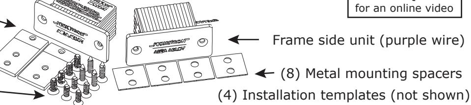
PowerJump™ ICPT Installation Instructions Package Contents
Door side unit (red wire)
- (4) Metal mounting tabs
- (8) 10/32 flathead machine screws
- (4) 8/32 flathead machine screws
- (4) #8 1" wood screws
- (4) #8 2 1/8" wood screws
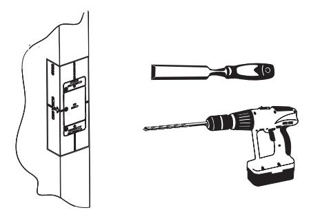
Recommended Tools
Screwdriver, drill, center punch wire nuts (22 gauge), tape Door Wedge
Metal Mounting Tools:
Rotary tool with cutting wheel 1/4" metal drill bit 82° countersink bit
Wood Mounting Tools:
Wood chisel and hammer 3/32" and 1/16" wood drill bits 1" Auger bit
500-24025
Rev A, 11/12
Specification
Input power at frame side: 500mA at 24V DC
Output power (selectable voltage) at door side: 250mA at 24V DC or 500mA at 12V DC
Operating temperature: 32 to 120 F / 0 to 49 C
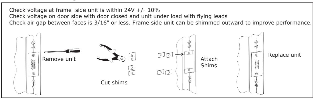
Maximum gap between faces: 3/16"
Compatibility: PowerJump does not support LBM, REX or other signals from the lock
Overview
The PowerJump ICPT transfers power across a door gap through magnetic inductive coupling.
Installation Steps
Step 1 : Survey installation site
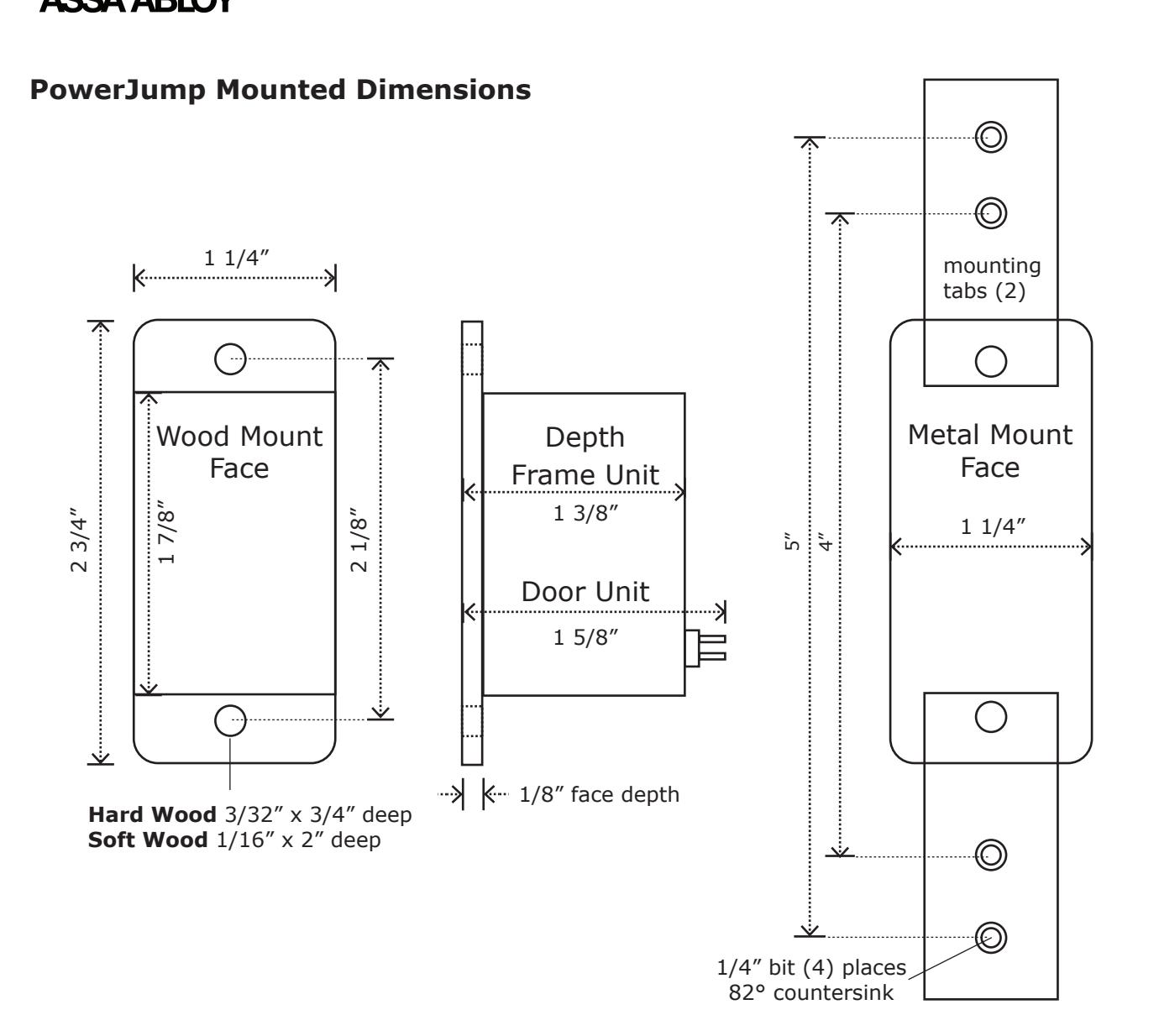
Unit may be installed on latch side, hinge side, top or bottom of door. Note the ICPT requires a depth of 1 3/8" in the frame and 1 5/8" in the door.
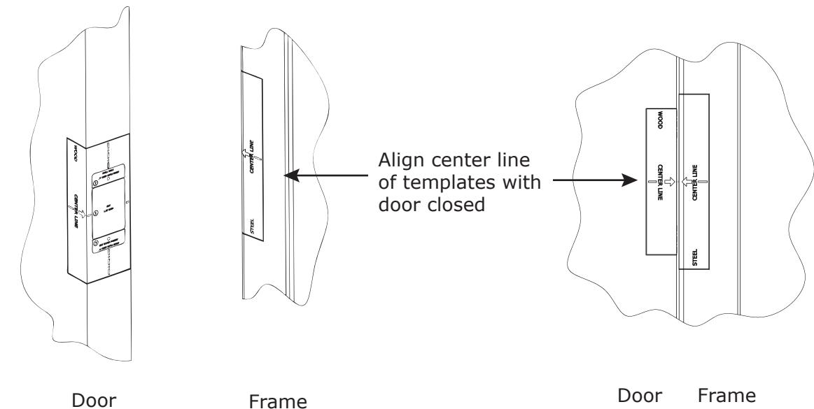
Step 2 : Select the template matching your door and frame material. Apply the templates as shown at the desired mounting location. Make sure the center line arrows are aligned when the door is closed.
© Copyright, 2012, all rights reserved Page 1
Troubleshooting:
Questions about Installation?
© Copyright, 2012, all rights reserved
Contact Securitron at: 1-800-MAGLOCK (800-624-5625)
Page 4
500-24025
Rev A, 11/12
_____________________________________
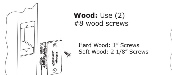
Step 3: Installing in a WOOD door or frame
Wood A: Carefully tap a chisel through the template to score the finish. Pre-Drill (2) mounting holes according to wood type.
Hard Wood: 3/32" bit, 3/4" deep Soft Wood: 1/16" bit, 2" deep
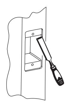
Wood C: Cut relief for faceplate using a chisel to a depth of 1/8"
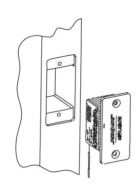
Wood E: Test fit the unit into the pocket and file if needed
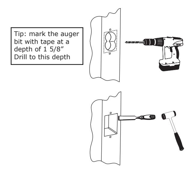
Wood B: Carefully drill out the pocket with the auger bit, to a depth of 1 5/8" Use a wood chisel to straighten the sides Be careful not to damage the surface
Wood D: Drill a wiring channel for connection to the device to be powered

ASSA ABLOY
Securitron Magnalock Corp. www.securitron.com Tel 800.624.5625
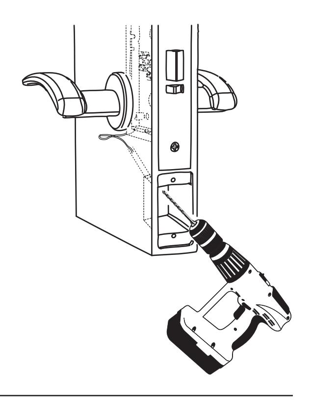
Step 4: Installing in a METAL door or frame
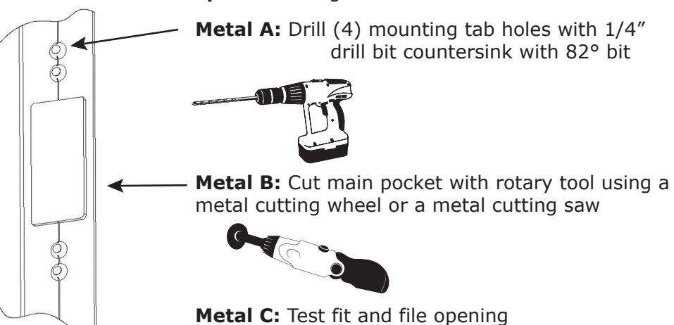
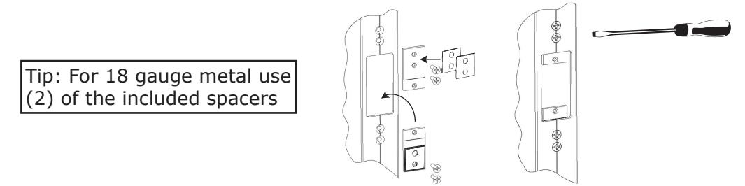
Metal D: Install mounting tabs using (4) 10/32 screws. Attach adhesive spacers as needed to mount the unit flush with the frame
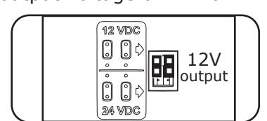
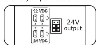
Step 5: Voltage Selection and Wiring
a) Select output voltage of 12V or 24V. Move the two jumpers as shown:
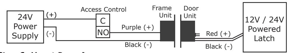
b) Supply 24V DC power to frame unit. Connect purple wire to positive (+) and black wire to (-). Connect door side electrified device via wiring channel, connect red wire to (+) and black wire to (-)
Page 3
Step 6: Mount PowerJump
Metal: Use (2) 8/32 machine screws to mount to tabs
© Copyright, 2012, all rights reserved Page 2
© Copyright, 2012, all rights reserved