Securitron HHD, HVD, HHSL, HHSR Installation Instructions
Open the original PDF document
View PDF

FULL LENGTH LOCK HOUSING MODELS HHD, HVD, HHSL AND HHSR FOR M32, M62 AND M82 MAGNALOCKS – INSTALLATION INSTRUCTIONS
1. DESCRIPTION
Securitron's full length Magnalock housings are furnished complete with a brushed stainless steel cover, two (2) end caps, an aluminum mounting plate and mounting hardware. These housings provide an attractive and secure lock installation option and are offered in three configurations:
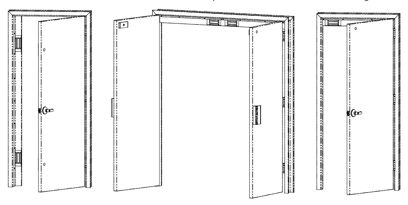
HVD
VERTICAL MOUNT DUAL LOCK SINGLE DOOR NON-HANDED
HHD
HORZONTAL MOUNT DUAL LOCK DOUBLE DOOR NON-HANDED
HHSL/HHSR
HORIZONTAL MOUNT SINGLE LOCK SINGLE DOOR HANDED (HHSR Shown)
2. OVERVIEW
Upon unpacking, an inventory should be made to ensure that all the required components and hardware have been included. Along with these instructions, the Full Length Housing package should contain the following items:
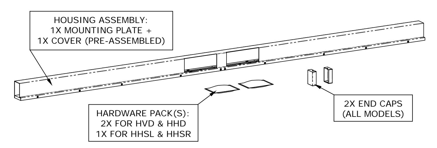
INCLUDED HARDWARE (Quantities shown are per single pack):
| 2X | All Models | 2X | All Models | 2X | All Models | |
|---|---|---|---|---|---|---|
| Phillips Head W/ Washer | Socket Head Cap | Blind Nut | ||||
| #8 X 1/2" TEK | 1/4-20 X 1" | 1/4-20 | ||||
| 2X | -32 Models | 4X | -62/82 Models | 8X | -32 Models |
|---|---|---|---|---|---|
| 9X | -62/82 Models | ||||
|
Socket Head Cap
1/4-20 X 1-3/4" |
Socket Head Cap
1/4-20 X 2-1/2" |
Phillips Flat Head
#12 X 1-1/2" Type "A" |
|||
3. RECOMMENDED TOOLS
- Hammer
- Center Punch
- Drill Motor & Bits
- Phillips Screwdriver: #2
- Wrench, 1/2" Open-end (or adjustable)
- Wrench, Hex, 3/16"
- Wire Strippers/Crimpers
- Pliers
- Metal File
4. INSTALLATION
Unpack the housing. Without disassembling, position the unit into its intended location to verify that it is the correct length/height for the door opening. For the dual Magnalock models (HHD and HVD), the lock/strike locations are equally spaced to each side of center of the housing as shown. (All dimensions displayed in brackets [XX.X] are in millimeters).
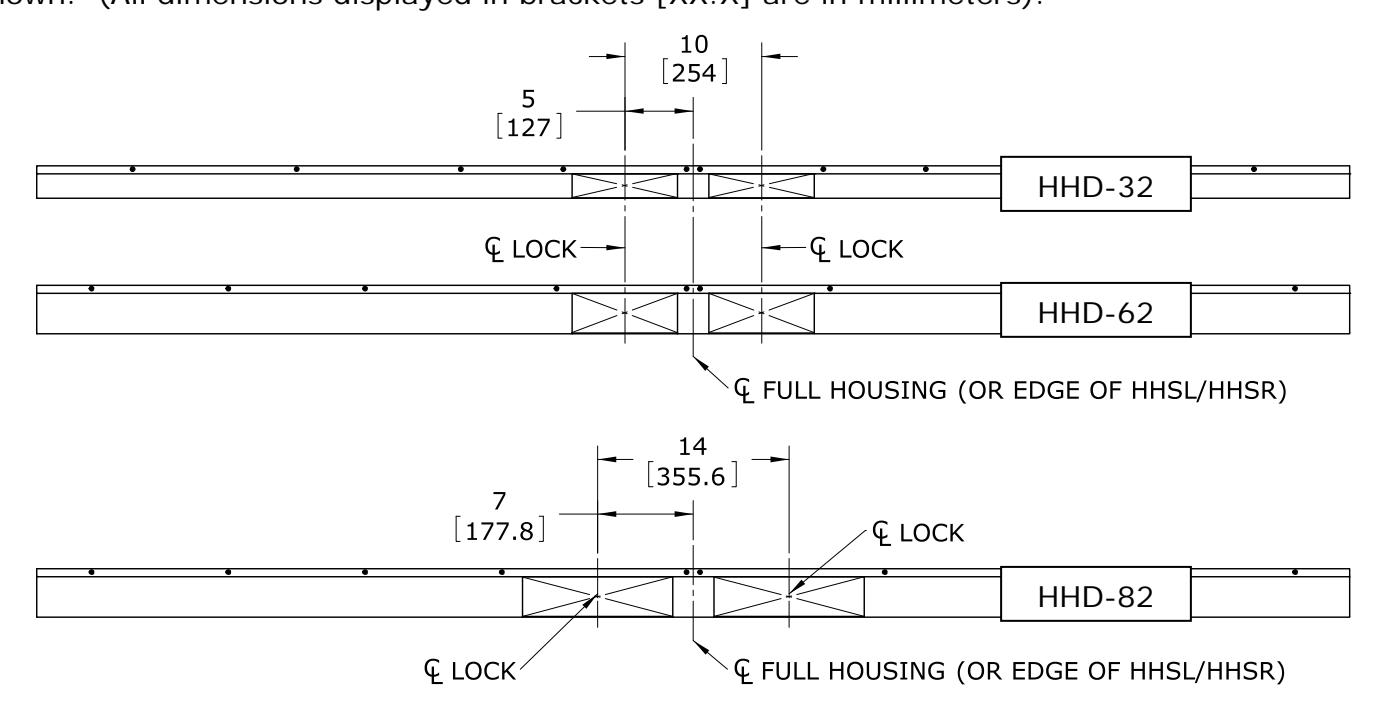
Figure 1
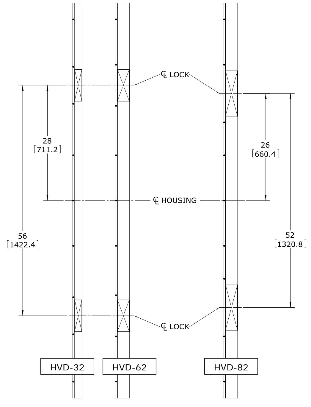
Figure 2
4.1 STRIKES
While maintaining the housing assembly in the desired position, mark the center of the housing on the door frame. Measure to each side of this center mark (using the dimensions shown in Figure 1 or Figure 2 as applicable) to indicate the centers of the magnets. Transfer these two marks to the door(s). This will provide the proper lateral position of the strike holes from the center of the housing.
NOTE : Full length HHD housings are cut in half to create the HHSL and HHSR models. Therefore, to locate lateral center of the strike for these models, use the 5" [127.0] dimension for M32/M62 models or the 7" [177.8] dimension for M82 models as previously shown in Figure 1. This will indicate the proper distance to the center of the strike from the end of the shortened housing.
The following illustrations display the required distance from the bottom of the mounting plate surface to the center of the strike mounting hole through the door.
PN# 500-16600 Page 3 Rev. D, 07/11
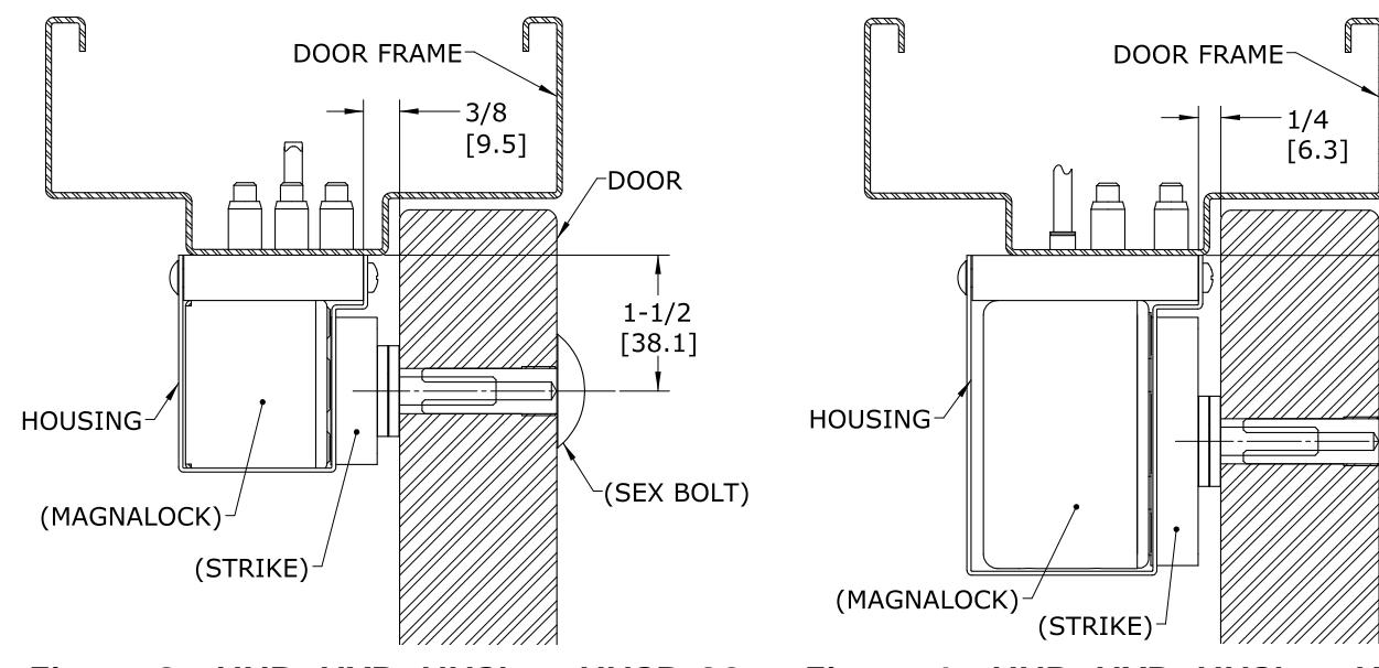
Figure 3 - HHD, HVD, HHSL or HHSR-32 Figure 4 - HHD, HVD, HHSL or HHSR-62/82
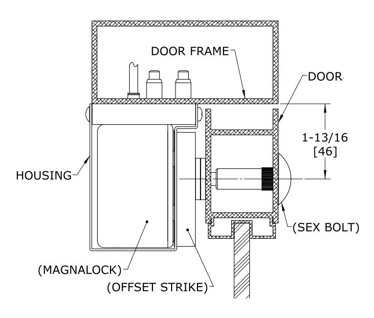
Figure 5 - M62 or M82 On Aluminum Frame (shown without stop)
NOTES FOR ALUMINUM FRAME DOOR OPENINGS:
- 1) Blade type stops should be removed from the frame to create access to the housing cover attachment screws.
- 2) A spacer plate (not included) must be installed under the mounting plate for stops which are too narrow to provide a sufficient mounting base. This will create the clearance over the stop that will allow access to the housing cover attachment screws.
- 3) IN EITHER CASE AN OFFSET STRIKE IS RECOMMENDED IN ORDER TO POSITION THE STRIKE MOUNTING HOLE AWAY FROM FEATURES INSIDE THE DOOR RAIL THAT MAY CAUSE INTERFERENCE WITH BOTH THE M62 AND M82 MODEL ASSEMBLIES.
PRIOR TO DRILLING STRIKE HOLES:
Double-check to verify that the markings for the strikes are in the required locations. Please be aware that the location of the strike in relationship with the Magnalock is important for the proper operation of the BondSTAT and the Door Position Sensor (if equipped). SEE THE MAGNALOCK INSTALLATION INSTRUCTION MANUAL AND PRODUCT TEMPLATE FOR COMPLETE STRIKE ALIGNMENT DETAILS AND INSTALLATION INFORMATION.
Center punch and then drill 3/8" [9.5] diameter holes completely through the door at the marked strike center locations. Then use the installation instruction manual, template and hardware included with the Magnalock to properly install the strike plate.
3.2 HOUSING AND MAGNALOCKS
Remove and collect the hardware for reuse and then remove the cover from the full length housing mounting plate.
In most cases the leading edge of the plate can be positioned away from the door at the distance shown in Figures 3 & 4 (i.e. 3/8" [9.5] for M32 and 1/4" [6.3] for M62/M82). However, in some cases it may be better to temporarily mount the Magnalocks to the mounting plate. This will allow for an accurate positioning of the mounting plate when the Magnalock(s) are placed directly against the strike(s) prior to marking or drilling the mounting hole locations.
Once the mounting plate is suitably positioned, it may be used as a template to mark/drill the holes required in the door frame.
FOR WOOD FRAMES:
Drill 3/16" [4.8] diameter x 1-1/4" [31.8] deep holes for wood door frame mounting.
FOR STEEL/ALUMINUM FRAMES:
Drill 3/8" [9.5] diameter holes through for each blind nut installation. (See the Magnalock installation instructions for detailed information on installing the blind nuts).
Drill 3/16" [4.8] diameter holes for each remaining bracket mounting hole.
Secure the mounting plate to the door frame using the provided hardware. NOTE: WHEN INSTALLING THE MOUNTING PLATE TO STEEL OR ALUMINUM DOOR FRAMES - USE OF 1/4-20 X 1" [25.4] SHCS AND BLIND NUT IS HIGHLY RECOMMENDED AT TWO (2) HOLE LOCATIONS ADJACENT TO EACH LOCK MOUNTING POSITION AS SHOWN IN FIGURE 6.
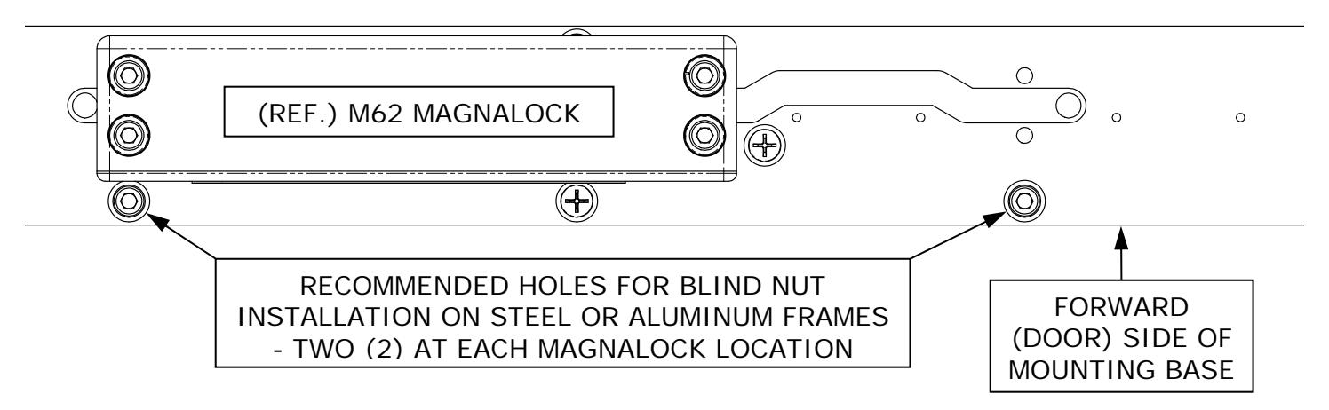
Figure 6
As an example, the following illustrations show the exploded assemblies of the Magnalock mounting ( Figure 7 ) and the cover assembly ( Figure 8 ) on a typical HHD-62 model full length housing.
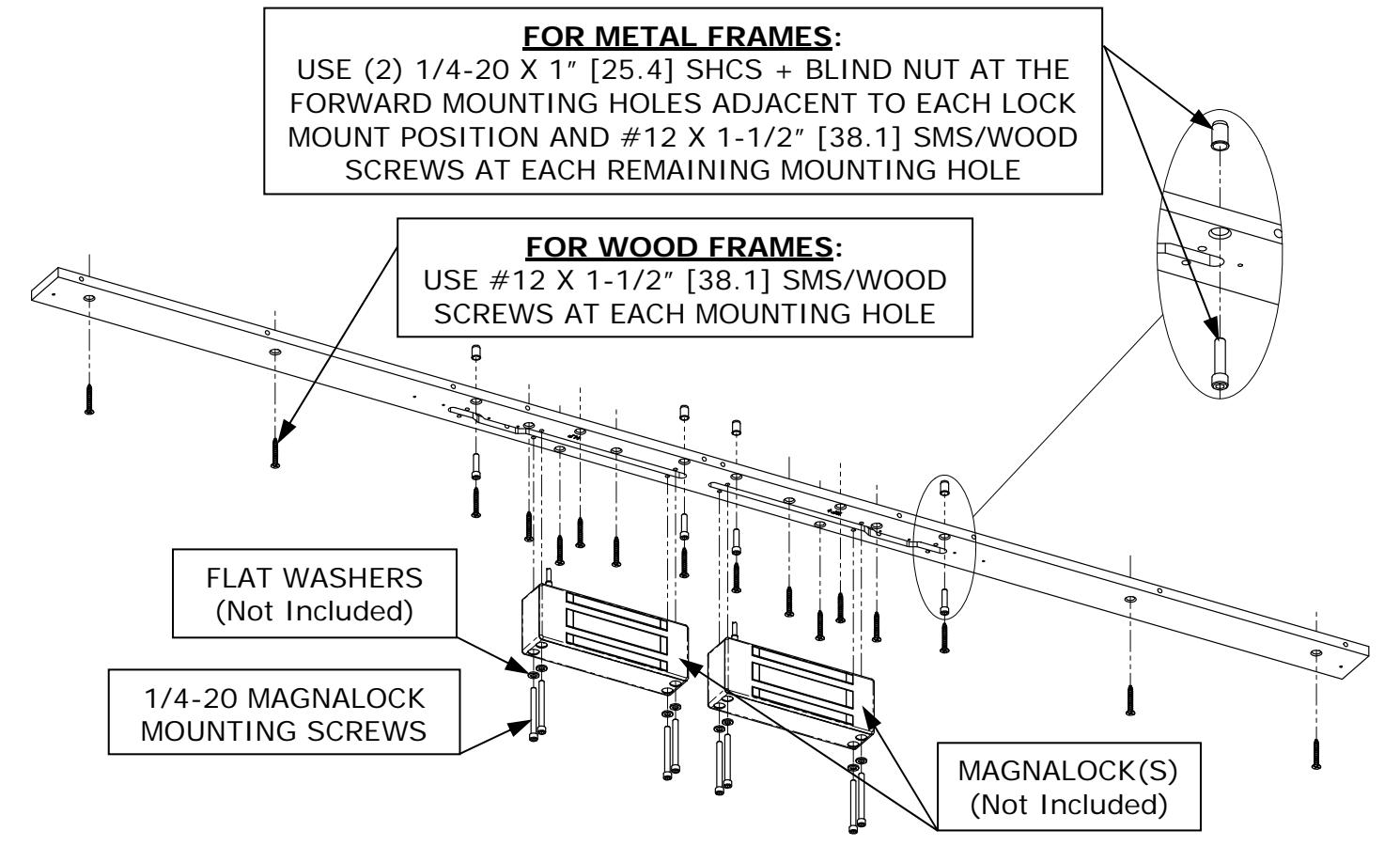
Figure 7
NOTE: Mounting holes are configured to provide a flush mount up to a #14 X 4" Flathead SMS/wood screw. These screws are not included, but may be utilized for an even more secure assembly to a wooden door header.
To provide for the lock cable, a 3/8" [9.5] diameter wire feed through hole may be drilled through the frame anywhere within the wire channel (slot) under each Magnalock mounting area.
Using the provided 1/4-20 mounting screws and the flat washers originally included with the Magnalock, install the Magnalock(s) to the mounting plate. Use a 3/16" hex wrench to tighten the screws.
Pre-drill two (2) 9/64" [3.6] diameter pilot holes for the end cap mounting. These holes may be drilled through the mounting plate for the TEK screws that hold the end cap in place.
Assemble the end caps to the mounting plate using the TEK screws provided.
Assemble the cover to the mounting plate using the collected (previously removed) hardware.
NOTE: The screws go to the front (door) side so that the tamper-proof sex bolts are to the exposed side of the assembly as shown in Figure 8.
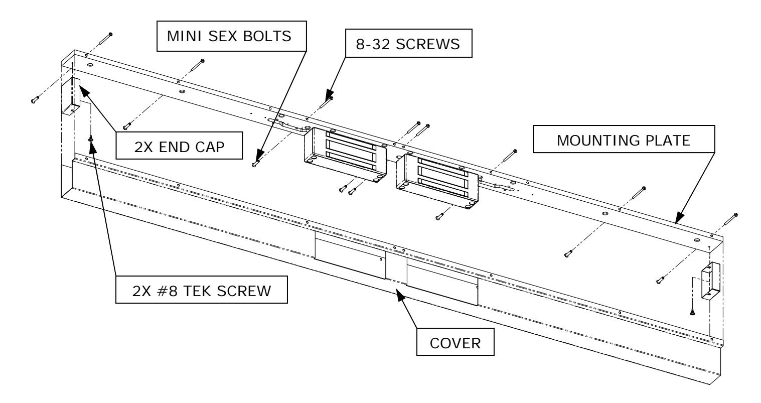
Figure 8
PN# 500-16600 Page 6 Rev. D, 07/11