Securitron GL1 Gate Locks Operating Manual
Open the original PDF document
View PDFSecuritron GL1 Lock Gate
Installation Instructions and Operating Manual
ASSA ABLOY
Experience a safer and more open world
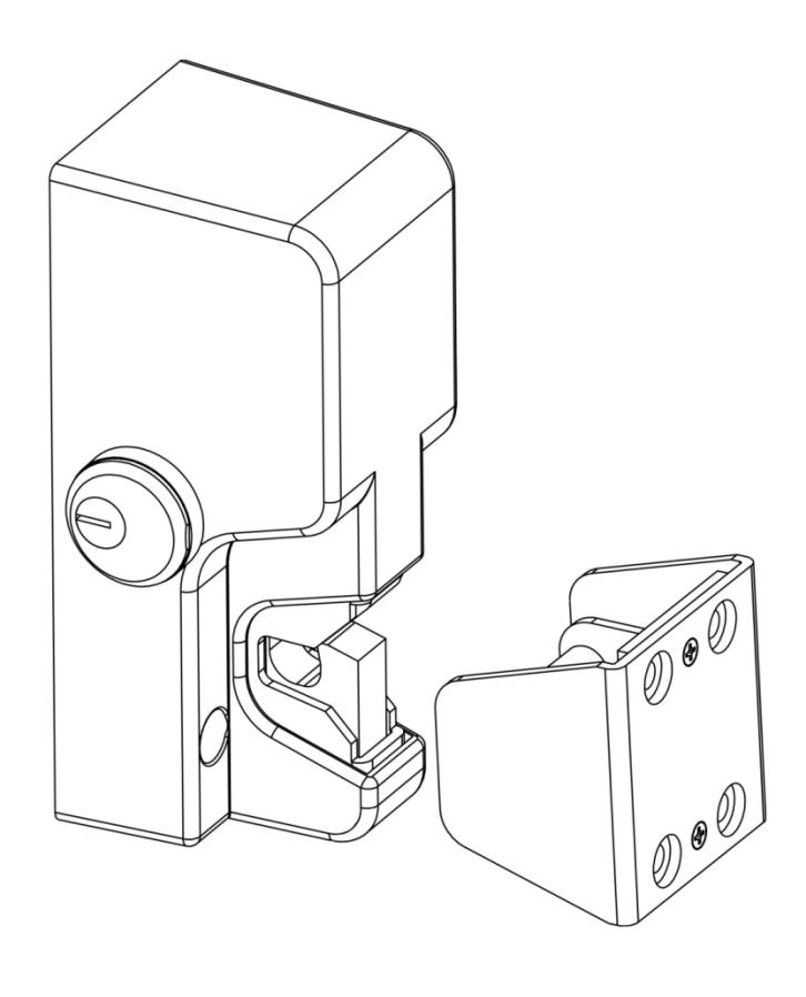
Table of Contents
| Table of Contents | 2 |
|---|---|
| Specifications | 3 |
| Physical | 3 |
| Electrical | 3 |
| Product Overview | 3 |
| Product Features: | 3 |
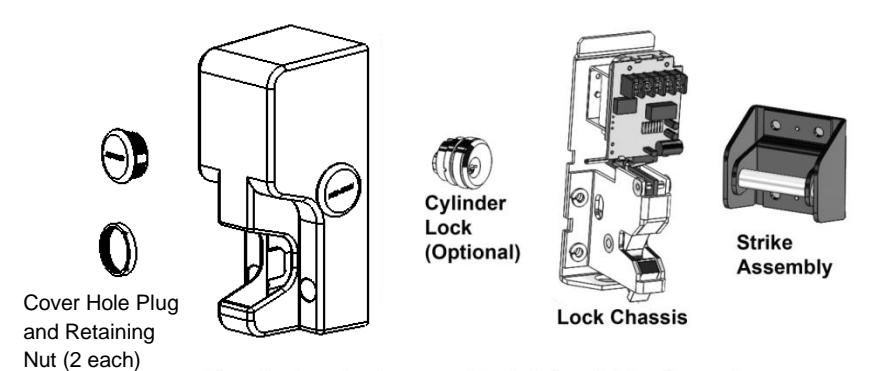
| Product Components | 4 |
| Recommended Tools | 4 |
| Installing the Securitron GL1 Electromechanical Gate Lock | 5 |
| Perform a Pre-Installation Survey | 5 |
| Perform the Cylinder Lock/Cover Hole Plug Installation | 8 |
| Mount the Securitron GL1 and Connect the Electrical | 11 |
| Complete the Securitron GL1 Installation | 14 |
| Operating Instructions | 14 |
| Troubleshooting | 15 |
| MagnaCare® Lifetime Replacement Warranty | 16 |
- •
- •
- •
- Manual key override (right or left hand)—Fail Locked only
- •
- •
- •
- •
- •
- •
- •
- •
- •
- •
- •
- •
• Convenience and accessibility of area to be protected: The lock assembly should be installed in a location that will not hinder or create a potential safety hazard to authorized personnel routinely accessing the protected area.
Because of the diversity in gate construction and installation configurations, optimum mounting platforms may be achieved by welding adequate size metal plates, channels or tubing to the fence frame and the gate. Formed angle and brackets along with appropriately sized fasteners may also be utilized to mechanically secure mounting platforms for the lock and strike.
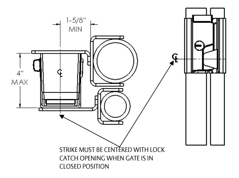
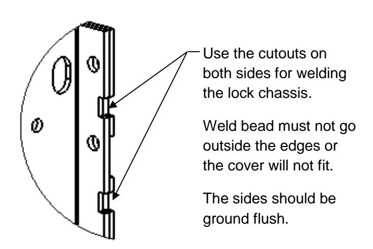
Figure 1, "Swinging Gate Mount," Figure 2, "Sliding Gate Mount," Figure 3, "Installation Spacing Dimensions," and Figure 4, "Chassis Welding," show some basic mounting configurations on a chain-link style fence frame and gate.
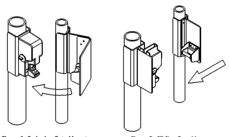
Figure 1. Swinging Gate Mount
Figure 2. Sliding Gate Mount
Perform the Cylinder Lock/Cover Hole Plug Installation
NOTE 1: The Securitron GL1 provides for the additional function of an optional key-operated cylinder lock. The cylinder lock can be installed to either side of the lock cover, because the Securitron GL1 lock latching mechanism features an actuator lever that will engage the cylinder lock from either side.
NOTE 2: IF the cylinder lock is <u>not</u> used, THEN a cover hole plug (provided) must be installed on both sides of the cover.
- SELECT the side of the lock cover that will be the most convenient for the key access after installation if installing the optional manual override.
- 2. INSTALL the optional cylinder lock.
NOTE: The following step is critical to the proper operation of the mechanical override. The cam of the cylinder ("MS" type) must come into contact with the actuator lever pin to operate the release trigger of the lock mechanism when the cover is assembled to the lock chassis.
- a. ASSEMBLE the cam, as necessary, so that the key rotation moves the cam to point toward the rear (opening) of the cover.
- b. INSERT the cylinder lock with applicable spacer (i.e., Sargent Number 90) into the applicable cover hole (see table below and Figure 5, "Cylinder Lock Installation").
| Size of Cylinder Lock | Spacer Required |
|---|---|
| 1" | 1⁄4" |
| 1 1/8" | 3/8" |
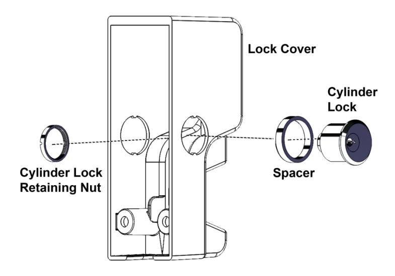
Figure 5. Cylinder Lock Installation
- c. SLIP the spacer over the cylinder lock and INSERT the cylinder lock into the applicable side hole on the lock cover.
- d. SLIP the lock mounting nut over the cylinder lock inside the cover and THREAD the nut onto the lock body by hand.
- e. TIGHTEN to secure the nut in place using the provided cylinder nut tool.
- f. INSTALL a cover hole plug in the opposite side of the cover, and SECURE its retaining nut using the provided retaining nut tool.
NOTE: The following steps are performed if the cylinder lock is <u>not</u> used.
- 3. INSTALL the two cover hole plugs (provided) through both sides of the cover (see Figure 6, Cover Hole Plug and Retaining Nut").
- 4. SECURE the cover hole plugs in place using the retaining nuts and provided cylinder nut tool (see Figure 6, "Cover Hole Plug and Retaining Nut").
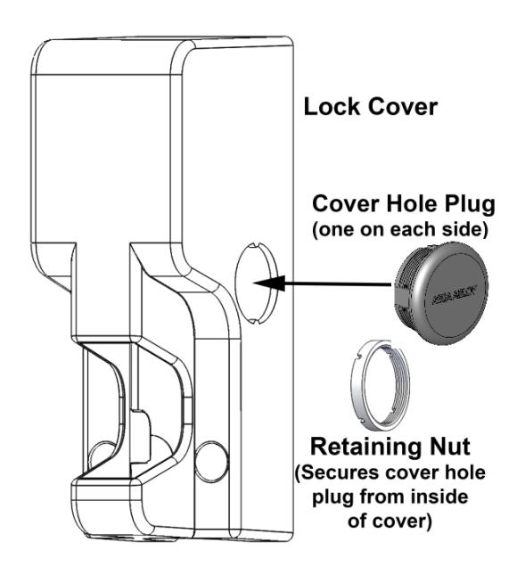
Figure 6. Cover Hole Plug and Retaining Nut
Mount the Securitron GL1 and Connect the Electrical
NOTE: The FMK-SL (Sliding Gate) and the FMK-SW (Swing Gate) mounting bracket kits are recommended for installing the GL1.
- IF not using one of the recommended mounting bracket kits, THEN USE the included template to locate and install mounting hardware.
- 2. INSTALL the lock chassis using the top two lock chassis mounting positions.
NOTE: The following chart shows wire gauge sizing versus voltage versus distance:
| Distance | Gauge 12V | Gauge 24V |
|---|---|---|
| 100 FT | 20 GA | 22 GA |
| 200 FT | 18 GA | 20 GA |
| 400 FT | 14 GA | 16 GA |
| 800 FT | 12 GA | 14 GA |
- 3. ROUTE all electrical wiring through either the provided wire conduit coupling in the bottom of the lock chassis or through the ½" [12.7 mm] hole in the rear of the lock mounting chassis (see Figure 7, "Wire Routing").
- 4. FEED wires through the hole in the side of the lock chassis opposite to the cylinder lock, if installed.
- 5. IF there is no cylinder lock installed, THEN FEED wires through either side of the lock chassis (see Figure 7).
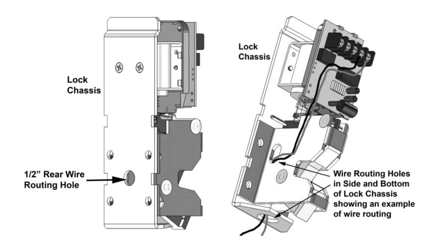
Figure 7. Wire Routing
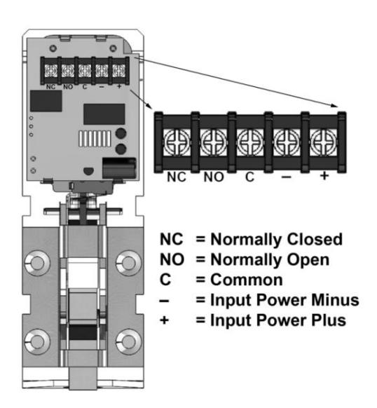
Figure 8. PC Board Terminal Block
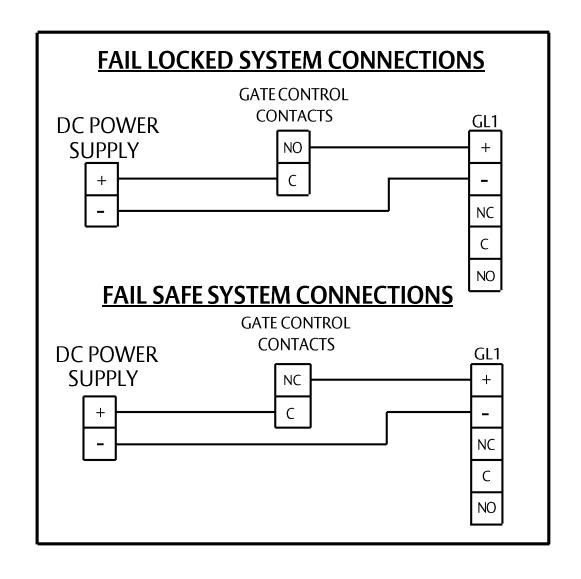
Figure 9. System Connections
7. PERFORM a functional test of the Securitron GL1.
Complete the Securitron GL1 Installation
CAUTION: Lock cover must be installed straight on to avoid possible damage to the PC Board.
- 1. INSTALL the lock cover over the lock mounting chassis by placing the cover straight on and then sliding to engage.
- 2. SECURE the cover to the mounting surface using two (2) socket head cap screws and two (2) split lock washers.
- 3. PLUG conduit fitting if not used, welding the plug for maximum security.
Operating Instructions
The Gate Lock is a direct-latching fail safe/locked electromechanical lock which incorporates Securitron's unique dual voltage system. The Securitron GL1 does not automatically
re-lock if the strike is not moved from the latch. The strike must always be pushed closed to mechanically re-latch in order for the GL1 to relock.
Fail Locked Version (GL1-FL): Applying input voltage of 12 or 24 volts DC, observing polarity (See Wiring diagram), will energize and unlock the Gate Lock allowing the gate to be opened. Removing the input voltage will de-energize the Gate Lock and will allow it to mechanically latch securely when the gate is closed.
<u>Fail Safe Version (GL1-FS):</u> The input voltage must be maintained to keep the Gate Lock in a locked mode. Removing the input voltage will de-energize and unlock the Gate Lock allowing the gate to be opened. Applying input voltage will energize and lock the Gate Lock awaiting the gate to be closed.
Additionally, the Gate Lock may include an optional gate status sensing feature. When the gate (strike assembly) is latched closed, the Gate Lock will report this closed condition by outputting a closed circuit condition between the C and NO terminals. When the gate is open, there is an open circuit between the C and NO terminals. This dry Single Pole Double Throw (SPDT) output can carry 1 Amp @ 30 VDC maximum.
Troubleshooting
PROBLEM: The lock does not latch.
- CHECK lock-to-strike engagement distance—strike may be mounted too far away from the lock.
- CHECK wire routing to ensure wiring does not impede the function of the lock mechanism manual override/actuator lever, or behind lock catch.
- ENSURE that there is power supplied to the unit and that the lock is wired correctly.
PROBLEM: The lock output does not report secure condition.
- CHECK wiring to ensure wires are connected to the appropriate terminals.
- CHECK status of lock/strike to verify that lock and strike are physically latched.
- CHECK for damage to monitor lever.
PROBLEM: The lock does not release.
- CHECK for excessive pre-load to lock—the gate lock latching mechanism is not designed to release under pre-loads in excess of 100 lbs (Fail-Secure only).
-
CHECK incoming voltage at the lock.
- For fail locked models, electrical power is required to energize and release the lock—VERIFY that there is power to the lock and that the voltage being delivered is within the operating specifications.
- For fail safe models, electrical power is removed to de-energize and release the locking mechanism—VERIFY that the power to the lock has been terminated.
- CHECK wire routing to ensure wiring does not impede the function of the lock mechanism manual override/actuator lever.
- ▪
- ▪
- ▪
- ▪
- ▪
- ▪
- ▪
- ▪