Securitron FAR-12, FAR-24 Installation Instructions
Open the original PDF document
View PDF

SECURITRON MODEL FAR-12, FAR-24, FIRE ALARM RESET MODULE INSTALLATION INSTRUCTIONS
1. DESCRIPTION
Securitron's Fire Alarm Reset (FAR) module interconnects with a Securitron BPS series power supply and a fire alarm (made by others). The purpose is to provide additional safety and control in an installation where activation of the fire alarm is intended to switch off the BPS power supply. This is often done to release power to magnetic locks installed on perimeter doors and permit safe evacuation in the event of a fire. The module has three specific functions:
- Maintains the released condition of devices released by activation of the fire alarm even after the fire alarm resets and until the module itself is reset by key.
- Allows key-controlled release of the same devices (separate from the fire alarm control).
- Signals the released or "normal" condition of the devices via a bicolor LED.
2. WIRING
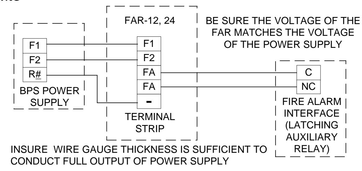
Figure 1: Interwiring between Fire Alarm Power Supply and FAR
Note that the designation "R#" in the power supply refers to any of the common DC negative terminals marked "R" in that unit and be sure that the gauge wire you select to make the above connections is sufficiently thick to handle the full output current of the power supply. Also, a ULlisted auxiliary latching relay with NC contacts of sufficient capacity to handle the full output of the power supply must be furnished as part of the fire alarm system (by the fire alarm system contractor).
3. OPERATION
Note that when first connected, the red LED on the FAR will be illumined and the devices connected to the system will be in the released condition (no power received). When the key is turned in the "reset" direction, the green LED will come on and the devices will receive power. The action of turning the key in the reset direction sets a relay interlock in the FAR.
At any later time, when the fire alarm activates, power to the devices will be immediately cut by the fire alarm auxiliary latching relay. The power is cut in a second place in the circuit by the FAR's internal relay which drops out. This will also happen if power is momentarily interrupted for any reason. For example, in a system where battery backup is not being employed, a momentary failure of building line voltage will drop out the FAR's relay interlock. The red LED will come on (when power resumes) and power will be denied to the devices until the key is turned in the reset direction.
The FAR can also be employed to manually cut off power. Momentarily turning the key in the off direction will drop out the relay interlock, cut power and illuminate the red LED. Power to the devices is restored by turning the key in the reset direction.
Finally, note that the FAR is delivered with a US type 1-1/8" mortise cylinder. This cylinder can typically be re-keyed by a local locksmith to accept keys which are already in use in the facility, if desired.
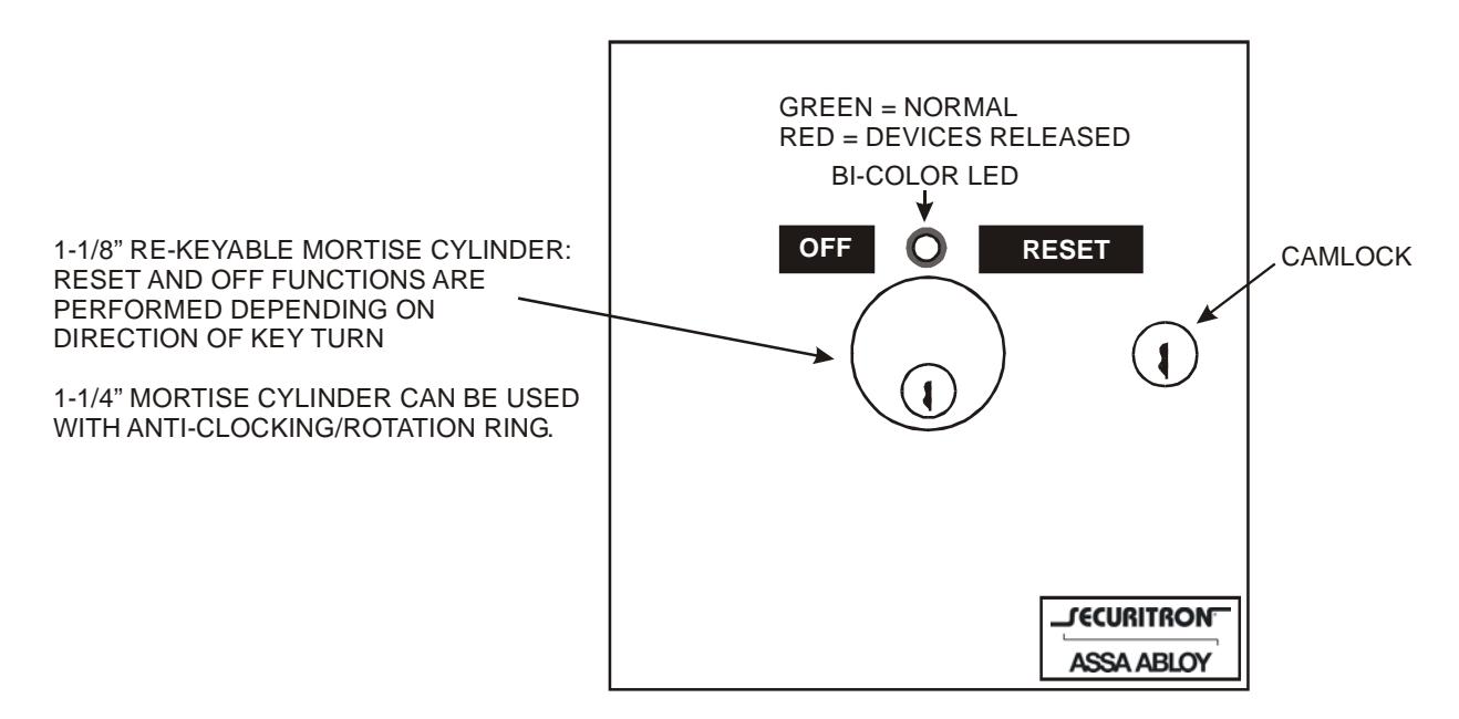
Figure 2: Front Panel of FAR