Securitron CEPT Power Transfer Installation Instructions
Open the original PDF document
View PDFASSA ABLOY
Securitron® CEPT Concealed Electrical Power Transfer
Installation Instructions
Experience a safer and more open world
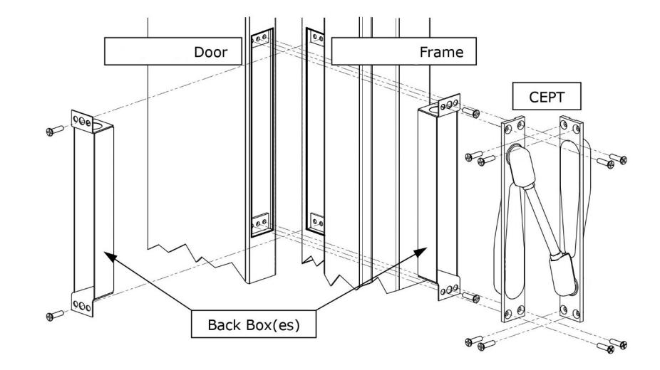
Product Components
- A CEPT Assembly
- B Back Box (x2)
- C Screws, 10-24 x 3/4" Phillips Flat Head Undercut (for metal) (x13)
- D Screws, #10 x 3/4" Phillips Flat Head (for wood) (x13)
- E Dolphin<sup>™</sup> Connector (CEPT-10 only) (x17)
- F Wire Nut (CEPT-10 only) (x4)
- G Strain Relief Bushing (x2)
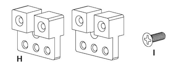
CEPT-TK (Option)
To be used when retrofitting CEPT into an unprepared metal door & frame
H CEPT-TK Mounting Brackets (x4)
I Screws, 8-32 x 1/2" Phillips Flat Head (x10)
B A A A A A A A A A A A A A A A A A A A
Diagram 2 Optional Components
Diagram 1 Product Components
Warranty
The CEPT is covered by the MagnaCare® lifetime replacement no fault warranty. No registration is required. Product will be replaced forever, for any reason, including but not limited to installation error, vandalism, or act of God. Replacement product is shipped at ASSA ABLOY's expense next day air if needed.
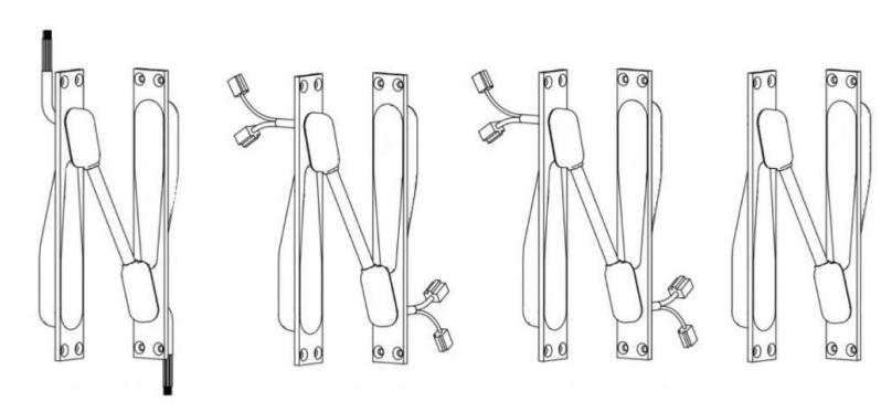
CEPT-10 Traditional, Connect 10 Wire (2 + 8) (2) Wire Nut + (8) Crimp
EL- CEPT ElectroLynx® (ASSA ABLOY) 12 Wire Connectors: 8pin + 4 pin
CEPT-C5E CAT 5e (TIA/EIA-568-B compatible) 9 Wire (8 + 1) Connectors: 6 Pin + 4 Pin
CEPT-NW No Wires Furnished
Specifications
Physical
For proper installation and operation of the CEPT, the thickness of the door should be 1-3/4" minimum. The door opening limitations listed here apply to a 1-3/4" door equipped with the following hinge sizes and configurations.
Door Swing Limitations
|
DOOR HINGE
CONFIGURATION |
DOOR OPENING
ANGLE RANGE |
|
|---|---|---|
| 4-1/2" to 5" Butt Hinge | 0–180° | |
| 5-1/2" Butt Hinge | 0–130° | |
| 6" Butt Hinge | 0–110° | |
| 3/4" Offset Pivot | 0–110° | |
Electrical (the following chart shows the electrical specifications for each CEPT model)
| MODEL | TYPE | WIRE SIZE/QTY |
CURRENT LIMIT
(PER WIRE) |
|---|---|---|---|
| CEPT-10 | 10 Wires | 18 AWG / 2 | Max. 5A |
| 22 AWG / 8 | Max. 1A | ||
| EL-CEPT | ElectroLynx® | 22 AWG / 12 | Max. 1A |
| CEPT-C5E | CAT 5e | 24 AWG / 8 | Max. 1A |
| 22 AWG / 1 | Ground (Max. 1A) | ||
| CEPT-NW | No Wires Furnished | (see note below) | Max. 1A |
NOTE: For the CEPT-NW, given the movement of the electrical power transfer during door movement, it is required that certain steps are taken to prevent wire breakage of 'installer provided' cabling.
1) Use only highly flexible cable with a robust flexible jacket. Flexible cabling is characterized by a high copper strand count (we recommend at least 19 strands) while a robust flexible jacket is at least 1/32" thick (with a maximum jacket OD of 0.275") made of PVC, PTFE, polyolefin or similar jacket material.
2) Provide for some wire slack for the wire entering and exiting the CEPT. The wire bundle must be free to move (approximately 1") within the CEPT during normal door movement to prevent wire breakage. As such, any splices or connectors should be at least 2" away from the exit of the power transfer device to ensure the wire is not restricted from moving within the CEPT during normal door movement. Although using the above recommendations reduces the risk of wire breakage, ASSA ABLOY cannot be held responsible for wire failure in power transfer devices in which ASSA ABLOY did not provide the wiring.
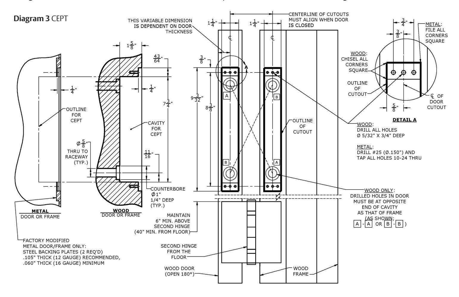
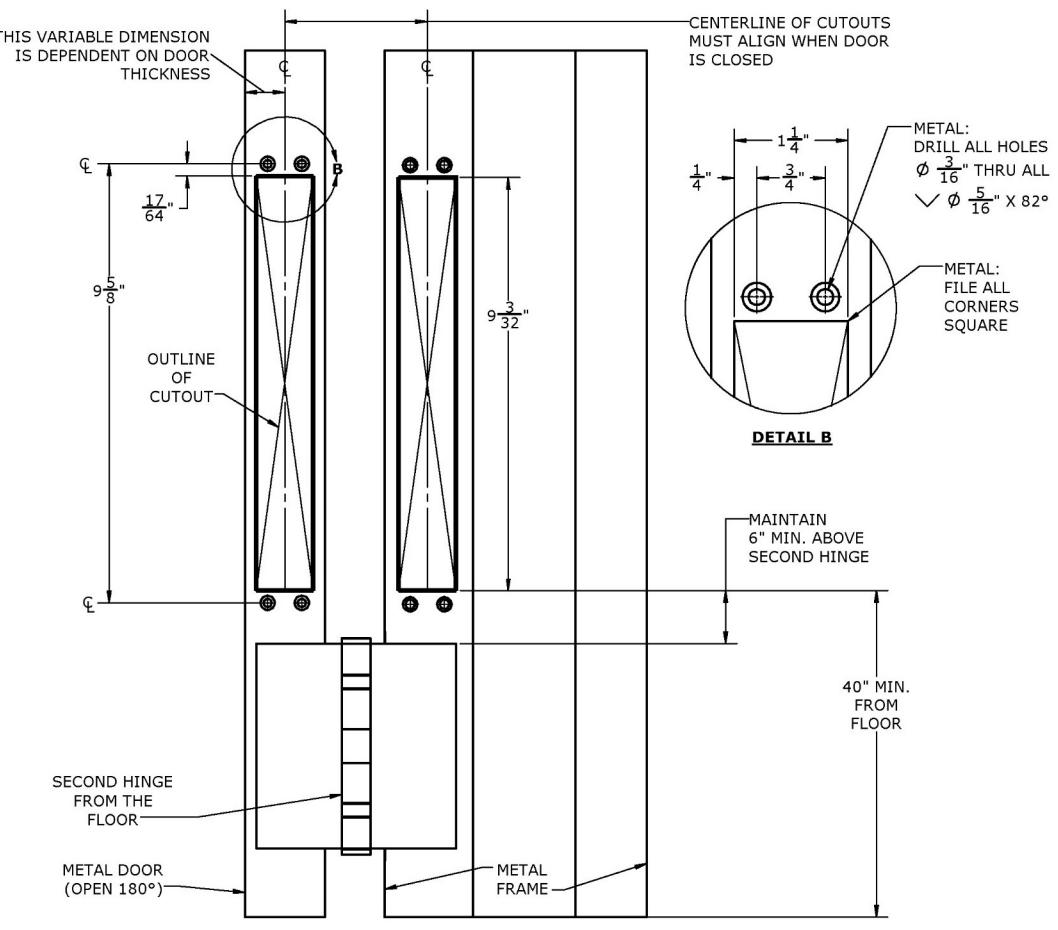
Prepare the Door & Frame for CEPT
If the door and frame have not been modified by the factory to accept the CEPT, then prepare the door and frame as shown in Diagram 3 . For metal door and frame installations, the CEPT-TK option will need to be installed, see Diagram 4.
Prepare the Door & Frame for CEPT-TK
For metal door and frame installations, the CEPT-TK option will need to be installed
Diagram 4 CEPT-TK
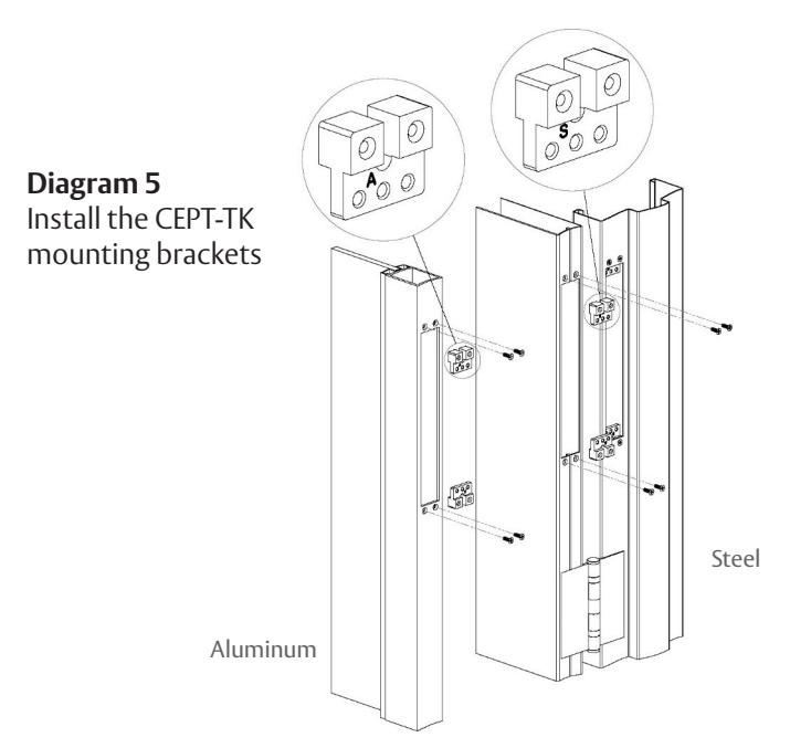
CEPT-TK Installation
For steel (or aluminum) construction without backing plates.
1 Orient the LETTER on the bracket facing out, see Diagram 5 .
NOTE: "S" is for steel door & frame construction "A" is for aluminum door & frame construction
- 2 INSERT Bracket inside of the cutout
- 3 SECURE with 8-32 x 1/2" screws
Installation
- 1 ROUTE CABLE through the holes in the door and the frame.
- 2 REMOVE KNOCK-OUTS from the back box NOTE: 7/8" diameter knock-outs for Electrical Metallic Tubing (EMT) 5/8" diameter knockouts for Strain Relief Bushing.
- 3 ROUTE CABLE thru 5/8" diameter knock-out.
- 4 INSTALL the strain relief bushing, see Diagram 6 : NOTE: ALLOW sufficient wire length (loop) for making connections
- 5 ATTACH BACK BOX with (1) screw thru the center hole
- 6 ATTACH CEPT with (2) screws thru outer holes
NOTE: Use 10-24 X 3/4 screws for METAL. Use #10 X 3/4 for WOOD see Diagram 7 .
7 Make Wiring Connections
- • CEPT 10 model: terminate the wire nuts for the two-18 AWG wires, and the Dolphin™ connectors (crimp type) for the eight-22 AWG wires.
- • EL-CEPT model: terminate the ElectroLynx® connectors
- • CEPT-C5E model: terminate the CAT 5e connectors
Diagram 6 Install the strain relief bushing
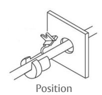
on Wire
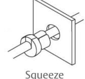
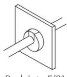
Squeeze Pliers
Push into 5/8" Knock-out
Knock-outs on back box
Diagram 7 Attach back box and CEPT