Securitron ASCWB-DM62CL, ASCWB-DM62CLM Brackets Installation Instructions
Open the original PDF document
View PDFTel 800.624.5625 techsupport@securitron.com in door opening solutions
MODEL ASCWB-DM62CL & ASCWB-DM62CLM ALUMINUM SPACER CONCRETE WOOD HEADER BRACKET INSTALLATION INSTRUCTION GUIDE
1. PRODUCT DESCRIPTION
leader
The ASCWB-DM62CL & ASCWB-DM62CLM are 1/2" [12.7mm] thick clear anodized aluminum spacer brackets designed for adapting to frame installations with the Model DM62 Magnalock. Installations that contain aluminum door frames with or without blade stops, wooden door frames, steel frames and/or concrete filled header frames may require a special spacer/structural type bracket. The purpose of the spacer bracket is to improve frame mounting strength, Magnalock/Strike clearances, alignments and ease of the installation. Applying the bracket, the DM62 Magnalock model becomes installable involving these frame types.
2. PRODUCT OVERVIEW
Upon unpacking this product, an inventory should be made to ensure that the required bracket and hardware have been included. Along with these instructions, the kit should include the items in the Figure 1 illustration below.
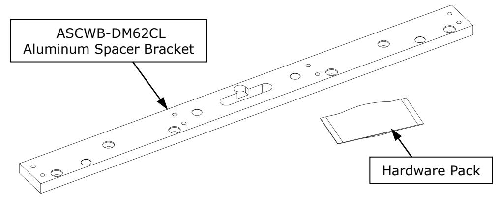
Figure 1
3. RECOMMENDED TOOLS
Power Drill Screwdriver: #2 or #3 Phillips 1/2" [13mm] Wrench or Adjustable
Center Punch 3/16" [5mm] Hex Wrench or 5mm 1/4" [6mm] Hex Wrench
Drill Bits: 3/16" [4.8mm], 7/32" [5.5mm] and 3/8" [9.5mm]
4. INSTALLATION INSTRUCTIONS
The instructions are divided into three (3) sections concerning all frame types. Details for installing to the various frame types are mentioned further in this installation guide.
4.1 ALUMINUM DOOR AND FRAME MOUNTING
4.1.1 ALUMINUM DOOR STRIKE ARMATURE MOUNTING
Mounting the strikes to an aluminum frame door may vary depending on the top rail (shoe) size and the internal structural design. When sex bolts are not adequate, a special blind nut may be installed using the same technique detailed in the DM62 installation manual. Figure 2 below illustrates the blind nut tool assembly before and after collapsing.
NOTE: OFFSET STRIKES MAY BE NECESSARY FOR FRAME STRUCTURE ALIGNMENT
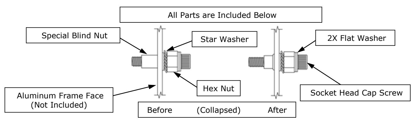
Figure 2
4.1.2 ALUMINUM FRAME MAGNALOCK MOUNTING
Mounting the spacer bracket onto an aluminum frame header requires use of the four (4) blind nuts, the four (4) socket head cap screws and the six (6) sheet metal screws provided. Proper use of the blind nuts and the additional sheet metal screws ensure a safe and secure mounting of the Magnalock reducing the possibility of the Magnalock becoming loose during regular use. Figure 3 illustrates a visual concept of the parts that will secure the bracket for the Magnalock installation.
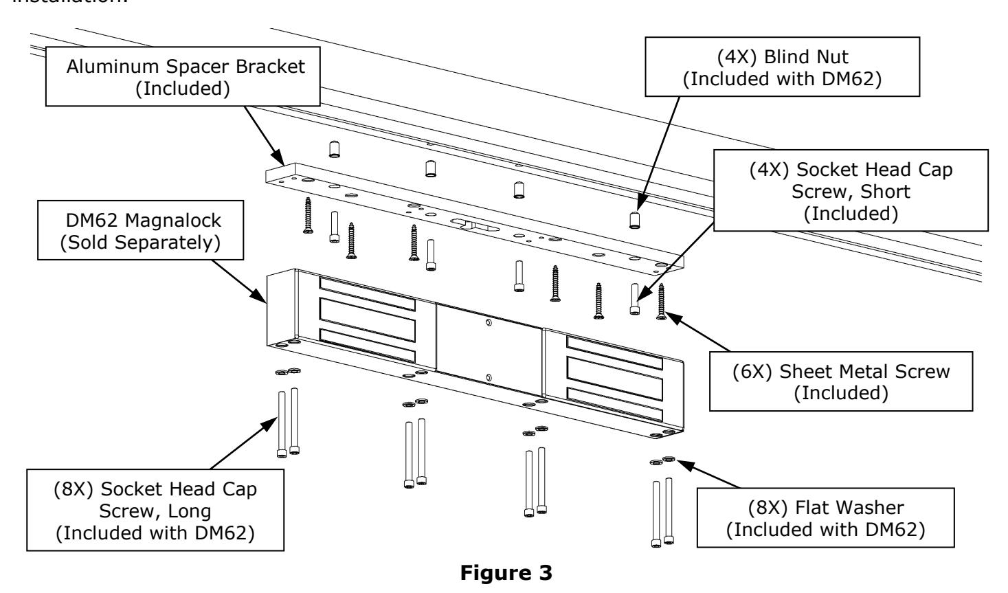
While installing the spacer bracket onto an aluminum type frame, follow the Step-By-Step procedures listed below:
- Position the bracket in the desired location on the frame with the "T" shaped slot facing downward and to the back side location of the DM62 Magnalock aiming away from the opening.
- Utilizing the spacer bracket as a template, mark the four (4) counter-bored holes where the blind nuts and socket head cap screws will be located.
- Drill the four (4) marked locations in the frame using a 3/8" [9.5mm] drill.
- Using the blind nut installation tool and the installation procedures provided in the DM62 package, mount the four (4) blind nuts.
- Mount the bracket onto the frame and securely tighten using the four (4) short socket head cap screws provided.
- Utilizing the six (6) counter-sink mounting holes remaining in the spacer bracket, drill 3/16" [4.8mm] holes x 1-1/2" [38mm] minimum depth, and install the six (6) sheet metal screws provided for additional strength.
- Drill the hole for the cable access into the frame utilizing the slotted area provided in the center of the spacer bracket.
- Position the DM62 Magnalock onto the spacer bracket while running the cables through the cable access hole and access panel area.
- Using the eight (8) long socket head cap screws provided with the bracket hardware and the eight (8) flat washers provided with the DM62 Magnalock hardware, securely mount the Magnalock into place.
4.2 WOOD FRAME MAGNALOCK MOUNTING
Mounting the spacer bracket onto a wood frame header requires the use of the six (6) wood screws provided. The wood screws mount through the frame and extend into the internal header to ensure a safe and secure mounting of the Magnalock reducing the possibility of the Magnalock becoming loose during regular use. Figure 4 illustrates a visual concept of the parts that will secure the bracket for the Magnalock installation.
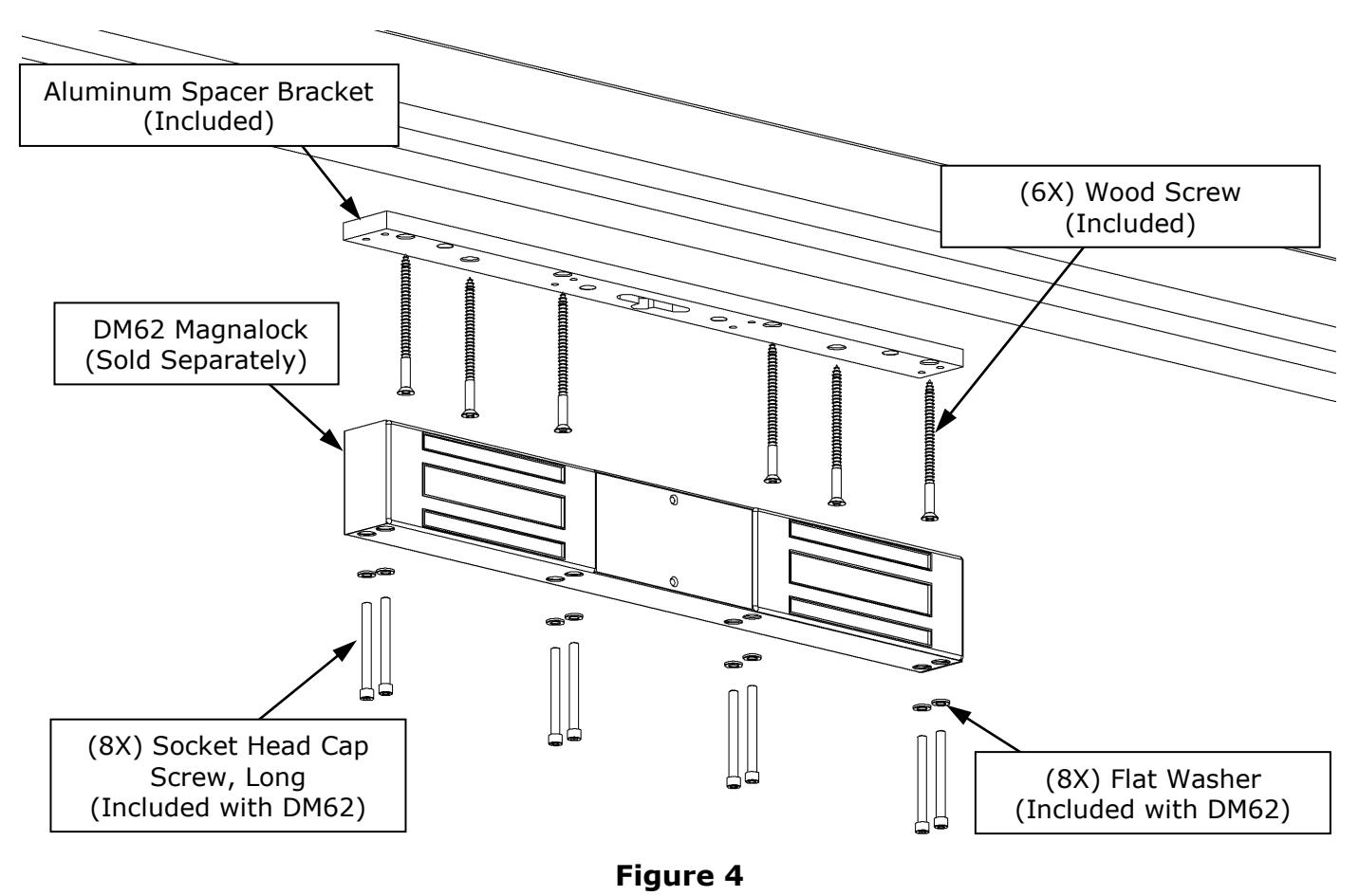
While installing the spacer bracket onto a wood type frame, follow the Step-By-Step procedures listed below:
- Position the bracket in the desired location on the frame with the "T" shaped slot facing downward and to the back side location of the DM62 Magnalock aiming away from the opening.
- Utilizing the spacer bracket as a template, mark the six (6) counter-sink holes where the wood screws will be located.
- Drill the six (6) marked locations in the frame using a 7/32" [5.5mm] drill to a minimum depth of 2-1/2" [64mm].
- Mount the bracket onto the frame and securely tighten using the six (6) wood screws provided.
- Drill the hole for the cable access into the frame utilizing the slotted area provided in the center of the spacer bracket.
- Position the DM62 Magnalock onto the spacer bracket while running the cables through the cable access hole and access panel area.
- Using the eight (8) long socket head cap screws provided with the bracket hardware and the eight (8) flat washers provided with the DM62 Magnalock hardware, securely mount the Magnalock into place.
NOTE: APPLYING FOUR (4) ADDITIONAL SHEET METAL SCREWS INTO THE REMAINING BRACKET MOUNTING HOLE LOCATIONS IS RECOMMENDED.
4.3 STEEL CONCRETE FILLED FRAME MAGNALOCK MOUNTING
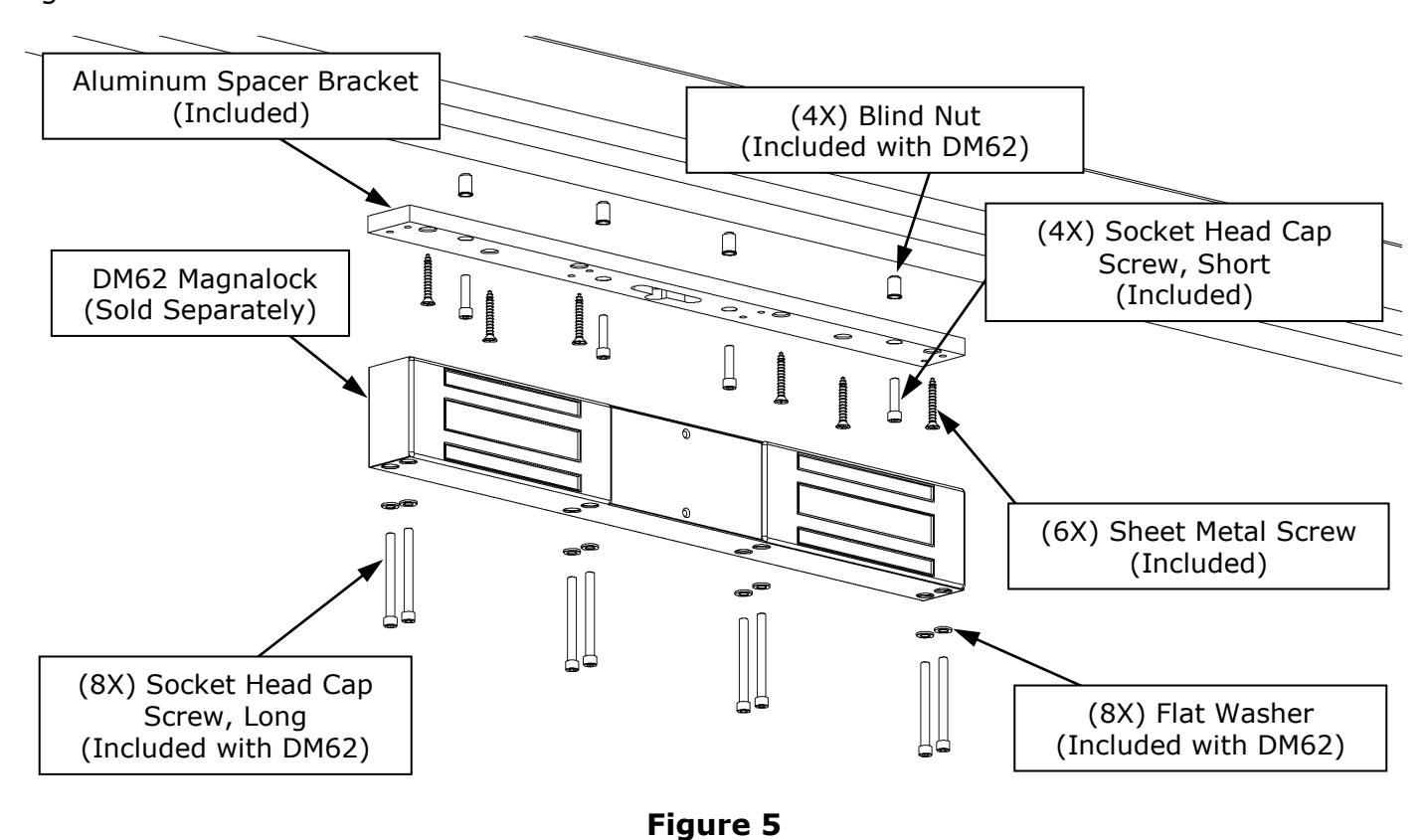
Mounting the spacer bracket onto a steel concrete filled frame header requires the four (4) blind nuts, four (4) short socket cap screws and the six (6) sheet metal screws provided for the installation. The blind nuts and the sheet metal screws ensure a safe mounting of the Magnalock reducing the possibility of the Magnalock becoming loose during regular use. Figure 5 illustrates a visual concept of the parts that will secure the bracket for the Magnalock installation.
While installing the spacer bracket onto a steel concrete filled type frame, follow the Step-By-
Position the bracket in the desired location on the frame with the "T" shaped slot facing downward and to the back side location of the DM62 Magnalock aiming away from the opening.
Step procedures listed below:
- Utilizing the spacer bracket as a template, mark the four (4) counter-bored holes where the blind nuts and the socket head cap screws will be located.
- Drill the four (4) marked locations in the frame using a 3/8" [9.5mm] drill to a minimum depth of 1-1/2" [38mm].
- Using a 3/16" [4.8mm] drill, carefully clear any concrete on the backside area of the frame to give clearance necessary to mount the blind nuts properly.
- Using the blind nut installation tool and the installation procedures provided in the DM62 package, mount the four (4) blind nuts.
- Mount the bracket onto the frame and securely tighten using the four (4) short socket head cap screws provided.
- Utilizing the six (6) counter-sink mounting holes remaining in the spacer bracket, drill 3/16" [4.8mm] holes x 1-1/2" [38mm] minimum depth, and install the six (6) sheet metal screws provided for additional strength.
- Drill the hole for the cable access into the frame utilizing the slotted area provided in the center of the spacer bracket.
- Position the DM62 Magnalock onto the spacer bracket while running the cables through the cable access hole and access panel area.
- Using the eight (8) long socket head cap screws provided with the bracket hardware and the eight (8) flat washers provided with the DM62 Magnalock hardware, securely mount the Magnalock into place.
NOTE: IF MOUNTING THE BLIND NUTS INTO THE CONCRETE FILLED FRAME HEADER IS NOT POSSIBLE, APPLYING THE ADDITIONAL SHEET METAL SCREWS INTO THE PROVIDED MOUNTING HOLE LOCATIONS IS RECOMMENDED.
PN# 500-22800 Page 4 Rev. D, 08/11