Securitron AQU126, AQU126-8C, AQU243, AQU243-8C Power Supplies Installation Instructions
Open the original PDF document
View PDFInstallation Instructions
AQU243 24vdc 3.3A Supervised Power Supply/Charger module
AQU126 12vdc 6.5A Supervised Power Supply/Charger module
Both mounted in an enclosure 14" x 9" x 3.5"
PDB-8C Power Distribution Module with 8 power-limited output circuits
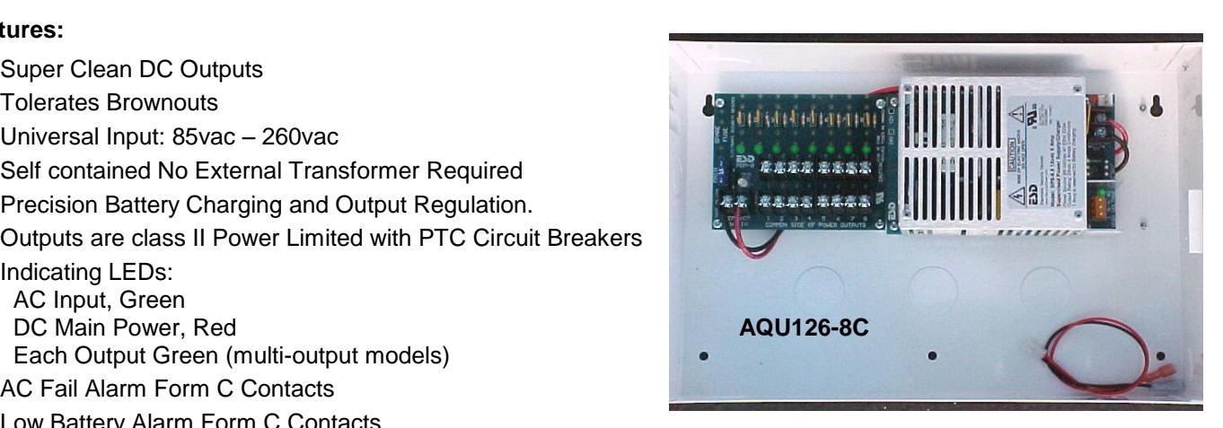
AQU243-8C – AQU243 with 1 PDB-8C-.72A providing 8 power limited outputs mounted in enclosure AQU126-8C – AQU126 with 1 PDB-8C-1.5A providing 8 power limited outputs mounted in enclosure
Features:
- Super Clean DC Outputs
- Tolerates Brownouts
- Universal Input: 85vac 260vac
- Self contained No External Transformer Required
- Precision Battery Charging and Output Regulation.
- Outputs are class II Power Limited with PTC Circuit Breakers
-
Indicating LEDs:
- AC Input, Green
Each Output Green (multi-output models)
- AC Fail Alarm Form C Contacts
- Low Battery Alarm Form C Contacts
- Battery Cut-off Relay Prevents Deep Discharge
- Battery is Float Charged for Faster Charging with No Switch Over when AC fails.
- Thermal Protection
- Short Circuit Protection
- Plug-in Battery cable assembly is provided
- 36" Plug-in Battery cable assembly is available (WA-36IBAT) for remote battery mounting.
- Quality Manufactured in the USA
- UL and CUL Listed Modules are UL and ULC 603 Burglar Alarm System Power Supply UL and ULC 294 Access Control Accessory UL and ULC 1481 & NFPA72 Power Supplies for Fire-Protective Signaling Systems
- Certified Compliance with EN 55022 & FCC

10027 S. 51st St., Ste 102 Phoenix, AZ 85044
Doc.# 500-33025 Rev. B Installation specifications subject to change without notice
Phone: (800) MAGLOCK customercare@securitron.com www.Securitron.com
AQU126 & AQU243 Description
The AQU243 and AQU126 are clean, efficient, heavy duty, low frequency off line switching power supplies with precision battery charger and power supervision. These supplies are so clean that they can be used anywhere a linear or switching supply is recommended. The filtering and switching systems we use are very similar to what you would find on high quality computers. Even though the AQU243 (24v) and the AQU126 (12v) are both 100 watt power supplies utilizing the same printed wiring board, we use separate supplies for 12v and 24v models for optimum performance. The universal input of 85vac to 260vac allows them to be used anywhere in the world without adjustments to the power input. The ability to run at very low AC voltages allows the AQU126 and AQU243 to tolerate brown outs very well. The AQU243 and AQU126 are fully self-contained and isolated from the AC power input line to all world safety standards. Each power supply weighs less than 1.5 lbs and occupies less than ½ of a cubic foot of cabinet space.
The AQU243 and AQU126 become an uninterruptible power supply when a stand by battery(s) is connected with the battery cable provided. These supplies have a special power limiting circuit that allows the batteries to be float charged across the output without lock up or chirping on and off. The battery(s) is protected with an automatic resetting circuit breaker and diode for over current and accidental reversed battery hookup. Precision float charging means faster recovery time and longer life for the battery(s). There is no switch over or voltage drop when input power fails. Standby battery(s) can be any capacity between 4 and 40 Amp hours. The AQU243 24vdc is rated for 3 Amps continuous current with 300ma reserved for battery charging. The AQU126 12vdc is rated for 6 Amps continuous current with 500ma reserved for battery charging.
Power Supervision utilizes 2 relays and electronics to indicate 2 levels of the stand by battery. The AC FAIL relay provides a form C contact set to indicate the AC has failed, the supply is running on standby batteries. The LOW BAT relay provides a form C contact set to indicate the battery(s) is low, not much stand by power is left. Either of these form C contacts can be used to signal a buzzer and/or other signaling device. Both of these relays are normally energized for fail-safe operation.
Battery-Cut Off uses a 3rd relay with electronics to disconnect the battery from the power supply and load at the end of it's service limit, preventing deep discharge that will damage the battery(s). This relay is normally energized as are the supervision relays.
PDB-8C-.72A/1.5A Description
The PDB-8C is a power distribution board. The PDB-8C converts a non power limited output to 8 class II power limited outputs. The PDB-8C works much like the circuit breaker panel you will find most homes. There is a main power input and a main fuse then the positive side is fed to 8 circuit breakers. The circuit breakers provide class II power limited outputs with fault isolation of each output circuit. Each circuit has a green LED to indicate its status. These output wires can be run outside of the enclosure without conduit. You must keep a minimum separation of .25" between power limited and non-power limited wiring.
Explanation of Terminals and LEDs
AC Input Terminals are marked High Voltage ( L )ine, ( N )eutral, and ( G )round. The terminal block and AC LED are mounted within a high voltage barrier. The terminal block is self-clamping and can accept wires from 12awg to 18awg.
AC LED adjacent to the AC input terminals is ON Green when AC is applied.
AC FAIL Terminals NO -Normally Open, C –Common, and NC –Normally Closed. The normal relay position indicates the AC power is on and the relay is energized. The terminal block is self-clamping and can accept wire from 14awg to 24awg. The contacts are rated for up to 2A resistive load to 120 volts. When the AC fails the relay drops off normal.
LOW BAT Terminals NO -Normally Open, C –Common, and NC –Normally Closed. The normal relay position is energized and indicates the output battery voltage is in the normal range. When stand battery(s) reach a low level, the relay drops off normal.
DC Output Terminals on the AQU243 and AQU126 are marked ( –DC+) output. The AQU243 has a DC output of 24vdc with 3 Amps of continuous current, reserving 300ma for battery charging. The AQU126 has a DC output of 12vdc with 6 Amps of continuous current, reserving 500ma for battery charging. The terminal block is self-clamping and can accept multiple wires from 10awg to 24awg. The Red LED adjacent to terminal block is ON when output voltage is present.
The AQU243 and AQU126 DC output is not class II power limited. The DC output of the AQU243 or AQU126 is fed to the distribution board where each output has a PTC circuit breaker. The outputs from the PTC circuit breakers are class II power-limited. You must keep a .25" minimum spacing of power-limited wires to non-power limited wiring.
The input and output terminals on the PDB-8C are self-clamping and can accept multiple wires from 10awg to 24awg. Each output has a Green LED adjacent to its output that indicates voltage present. Adjacent to the input terminals of the PDB-8C board is main Power LED and Fuse. The fuse is an ATO automotive type. Replace with recommended size. The main power LED will be Green when main power is on. If polarity is incorrect the main LED will light RED.
DC Power LED adjacent to battery connector is ON Red when main DC is on.
Battery Connector is marked –Bat+ . This is a .156" 2 position header with lock. The provided battery cable plugs in to this. The provided cable is 12" long. For remote battery mounting, a 36" battery cable is available, part WA-36IBAT. The battery cable wires are Red and Black. The red connects to the positive and black to the negative of the battery. The AQU243 24vdc model comes with a 15" black wire with female slip on connectors on each end for connecting 2 12v batteries in series.
Specifications
|
AC Input: 3 position terminal block in High Voltage barrier. Line, Neutral, and Earth Ground
AC Input 90-250vac/47-63Hz/150W |
|---|
| AC Led indicator Green |
|
Note: The Ground connection is connected to the enclosure back with a metal stand off. In the case of
enclosures with a removable lid, a ground wire is used to ensure the ground continuity to the lid. If lid is removed, this ground wire must be reconnected securely. |
|
Wide range AC input does not require any selection switching. Earth ground terminal must be properly connected to
earth ground. |
|
AC Fuse Link is inside unit for catastrophic failure. This fuse is not field replaceable, unit must be returned to factory
for service should this fuse blow. A blown fuse is indicated by the AC Led indicator off with AC power applied. |
| DC Outputs: |
| AQU243 Total Continuous Output rating (not power limited) 20.0-27.8vdc, 24vdc nominal, 3A |
|
AQU243-8C
with PDB-8C720A Outputs 1-8 Power Limited Class II PTC circuit breakers rating 720ma |
| AQU126 Total Continuous Output rating (not power limited) 10.0-13.9vdc, 12vdc nominal, 6A |
|
AQU126-8C
with PDB-8C-1.5 Outputs 1-8 Power Limited Class II PTC circuit breakers rating 1.50A |
|
PDB-8C (C option) has main LED and 8 output LEDs
adjacent to each output (8) Green |
|
Typical Output Voltage
AQU243/AQU126 27.3vdc/13.65vdc |
| Typical Output Ripple & Noise AQU243/AQU126 50mv/25mv |
| Current Overload Short Circuit Protection Yes |
| Battery PTC Circuit Breaker AQU243/AQU126 3A/6A |
| Main Power LED adjacent to battery connector RED |
| Over Temperature protection Yes |
|
oC to 49oC
Ambient Operating Temperature Range 0 |
| Switching Frequency 27KHz |
| Supervisory Functions: |
| Battery Cutoff Voltage AQU243/AQU126 10.2vdc/20.4vdc |
| Battery Cutoff relay contacts (no user connections) 15A Resistive |
| AC fail trip point AQU243/AQU126 <25.8vdc/12.9vdc |
| AC fail trip point equates to about 99% battery capacity remaining |
| AC fail relay form C Contacts 2A up to 120vac |
| Low battery trip point AQU243/AQU126 <22.0/11.0vdc |
|
Low battery relay form C
Contacts 2A up to 120vac |
| AC fail, Low Battery, and Battery cut-off Relays are normally energized for fail-safe operation. |
| Battery Charging: (Header plug marked –Bat+) |
|
The battery charger is precision set to float charge 12v or 24v sealed or wet lead acid batteries. Typically two 12v
batteries are connected in series for 24v. The Amp hour capacity must be between 4Ah and 40Ah capacity. |
| Mechanical Characteristics: |
| AQU243/AQU126 weight (module only) 1.5 lbs |
Installation Instructions AQU126, AQU126-8C, AQU243 and AQU243-8C
|
AQU243-8C/AQU126-8C
weight in enclosure 7.6 lbs |
|
|---|---|
| AQU243/AQU126 (module only) size 6.40H" x 3.95"W x 2.5"D | |
| AQU243/AQU126 module mounting holes center to center (4 holes) 5.36"H x 3.54"W | |
| "E" Enclosure size (inside dimensions) 14W" x 9H" x 3.5"D" | |
| "E" Enclosure mounting holes center to center (4 holes) 12.74" x 6.98" | |
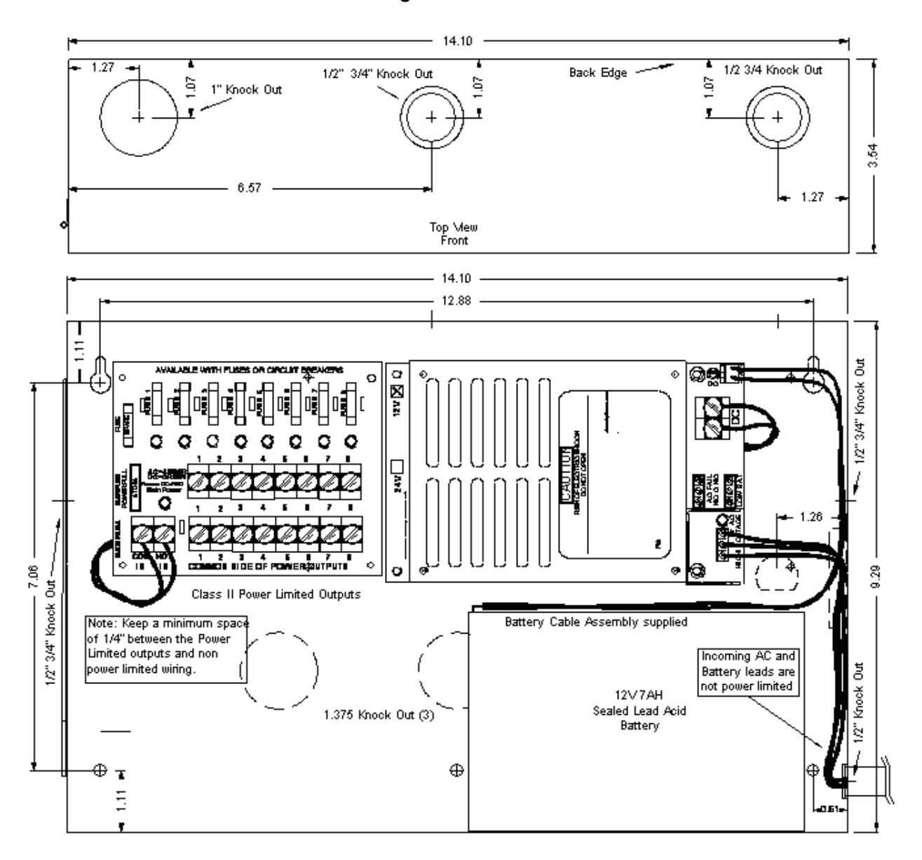
| Note: For knock out and mounting details, see diagram AQU126-8C on page 5. |
Approvals: EMI Conducted and Radiated
EN5022 CISPR-22 A, FCC A
UL and CUL Listed 603, C603-M1988 UL294, C294, UL1481, C1481
Specifications are subject to Change without notice.

Battery Selection
The table below shows typical standby time in hours for various loads and batteries. The table works for either AQU243 24v, or AQU126 12v.
Approximate Battery Standby Time Table with a reserve of 3 Amps for 5 minutes for Alarm
| Total Output | 4Ah Battery | 7Ah Battery | 12Ah Battery | 24Ah | 40Ah |
|---|---|---|---|---|---|
| Amps | Standby | Standby | Standby | Standby | Standby |
| .5A | 5.5 Hrs | 12 Hrs | 20 Hrs | 40 Hrs | 65 Hrs |
| 1A | 2.5 Hrs | 5 Hrs | 9 Hrs | 19 Hrs | 32 Hrs |
| 1.3A | 2 Hrs | 4 Hrs | 7.2 Hrs | 15.5 Hrs | 24 Hrs |
| 2A | 1 Hrs | 2 Hrs | 5 Hrs | 10 Hrs | 15 Hrs |
| 3A | .5 Hrs | 1 Hrs | 3 Hrs | 6 Hrs | 9.5 Hrs |
| 4A | .5 Hrs | .8 Hrs | 2 Hrs | 4 Hrs | 8 Hrs |
| 5A | NA | .6 Hrs | 1.4 Hrs | 3 Hrs | 7 Hrs |
| 6A | NA | .4 Hrs | 1 Hrs | 2 Hrs | 4 Hrs |
The recharge table below gives approximate recharge times for different loads and battery sizes.
The table is based on batteries depleted to battery cut-off and recharged back to approximately 90% capacity.
Approximate Battery Recharge Times in Hours
|
Total Output
Amps |
4Ah Battery
12v/24v |
7Ah Battery
12v/24v |
12Ah Bat
12v/24v |
24Ah Bat
12v/24v |
40Ah Bat
12v/24v |
|---|---|---|---|---|---|
| .5A | 8Hrs/8Hrs | 10Hrs/10Hrs | 13Hrs/13Hrs | 14Hrs/15Hrs | 24Hrs/24Hrs |
| 1A | 8Hrs/8Hrs | 10Hrs/12Hrs | 13Hrs/13Hrs | 14Hrs/15Hrs | 24Hrs/24Hrs |
| 1.3A | 8Hrs/12Hrs | 10Hrs/12Hrs | 13Hrs/16Hrs | 14Hrs/16Hrs | 24Hrs/26Hrs |
| 2A | 8Hrs/14Hrs | 10Hrs/12Hrs | 13Hrs/16Hrs | 14Hrs/17Hrs | 24Hrs/28Hrs |
| 3A | 8Hrs/16Hrs | 10Hrs/16Hrs | 13Hrs/20Hrs | 14Hrs/20Hrs | 26Hrs/38Hrs |
| 4A | 8Hrs/NA | 10Hrs/NA | 14Hrs/NA | 15Hrs/NA | 28Hrs/NA |
| 5A | 9Hrs/NA | 12Hrs/NA | 15Hrs/NA | 17Hrs/NA | 32Hrs/NA |
| 6A | 10Hrs/NA | 16Hrs/NA | 18Hrs/NA | 22Hrs/NA | 38Hrs/NA |
Maintenance
The power supply and stand by battery(s) should be tested at least once a year as follows:
- 1. Check LEDs for normal state. AC ON Green, DC ON Red, Output ON Green (multi-output models).
- 2. Check output voltage with normal load. The AQU126 should read between 13.6 and 13.8vdc. The AQU243 should read between 27.3 and 27.7vdc. This assures proper voltage to float charge batteries.
- 3. With normal load, disconnect AC input. AC LED should be off, all other DC LEDs should remain normal.
- 4. Check DC Output to be above 12.1vdc for AQU126 and 24.2vdc for AQU243. This checks standby batteries to be operational. Sealed lead acid batteries have a typical life of 3 to 5 years.
- 5. Re Apply AC and verify AC LED ON
Diagram AQU1268C
AQU126, AQU126-8C, AQU243 and AQU243-8C Supervised Power Supply/Chargers Installation Guide
The AQU243 and AQU126 Supervised Power Supply/Chargers with standby battery(s) provide an uninterruptible 24vdc or 12vdc power source. The DC output of AQU243 and AQU126 power supply module is not power limited. The 8 DC outputs of AQU243-8C and AQU126-8C are class II power limited outputs, each with PTC circuit breaker protection. Keep ½" minimum spacing between non power limited and power limited wiring.
- 1. This installation should be made by a qualified service person, should conform to all local codes and should comply with The National Electrical Code (or equivalent).
- 2. Mount the Power Supply in desired location.
- 3. For AQU243 and AQU126single output units. Connect DC devices to the Output Terminals. Not power limited. Observe polarity.
- 4. For AQU243-8C and AQU126-8C multi-output units connect DC devices to the output terminals on the PDB-8C board. (-) Negative power is the bottom row of terminals marked common 1 8. (+) Positive power is the top row of terminals marked 1 8. These terminals are just under the green status LEDs. Each (+) terminal is protected with a PTC circuit breaker. Observe polarity. These outputs are Class II Power Limited.
- 5. The power table below shows the continuous current you may use for each output.
- 6. Be sure that the total current requirement conforms to the total available output current.
- 7. Connect AC FAIL alarm contacts. N/O means normally open with AC ON.
- 8. Connect LOW BAT alarm contacts. N/O means normally open with battery voltage normal.
- 9. Connect Line voltage, 90 to 260vac and Earth Ground to the 3 position terminal block marked HIGH VOLTAGE. The Earth Ground terminal is connected to the enclosure and outer heat sink case for safety and EMI filtering. (L= line), (N=Neutral), and (G=Ground)
- 10. To reset a tripped PTC Circuit Breaker, you may have to correct fault and remove load for up to 1 minute. This allows the PTC re-settable fuse to cool and reset to it's normal "ON" condition.
Selection Table
Part number is shown on outside label.
|
AQU243
AQU126 Power Supplies |
Total
Continuous DC Amps |
Reserved for
Battery(s) Charging |
DCV Output |
PDB-8C Power
Limited Class II Outputs 1-PTC circuit breakers Rating |
PDB-8C Main
Power Pull Replacement Fuse |
AC Input rating |
|---|---|---|---|---|---|---|
| AQU243 | 3 Amps | 300ma | 24vdc | None | None |
85-260vac
150w |
| AQU243-8C | 3 Amps | 300ma | 24vdc | 720ma | 7.5A ATO |
85-260vac
150w |
| AQU126 | 6 Amps | 500ma | 12vdc | None | None |
85-260vac
150w |
| AQU126-8C | 6 Amps | 500ma | 12vdc | 1.50A | 15A ATO |
85-260vac
150w |
The DC outputs of the AQU243-8C and AQU126-8C are class II power limited. The output on the AQU243 & AQU126 is not power limited. Dress wires to keep a minimum space of .25" between non-power limited and power-limited circuits.
C(UL)US LISTED
Enclosure "E": 14W x 9"H x 3.5"D Power Supplies
UL and ULC 603 Listed Burglar Alarm System UL and ULC294 Listed Access Control UL and ULC 1481 Listed Fire-Protective Signaling