Securitron AQD5B AQ Power Boards Installation Instructions
Open the original PDF document
View PDF

AccuPower AQD5B Installation Instructions
#2 Phillips Screw Driver Wire connectors Lead Acid or Gel Cell Batteries*
1/16" Flat head Screw Driver 6-32 x 1/4 Mounting Screws (QTY 4)
AccuPower AQD5B Power Supply/Battery Charger Specifications
| Mechanical | Electrical | Environmental | Regulatory |
|---|---|---|---|
|
Physical Size:
Board: 6 1/8" x 3 7/8" x 2 1/8" Mounting: 4 1/2" x 3 3/8" Weight* AQD5B 1.4 lbs |
Input Voltage Operating Range
110-240VAC 47-63Hz Maximum Output Voltage 72 VA 6 Amps @ 12VDC (±10%) 3 Amps @ 24VDC (±10%) Continuous Output Voltage: 5 Amps @ 12VDC ((±10%) 3 Amps @ 24VDC (±10%) |
Operating
Temperature 0ºF to 130ºF [-17 to 54ºC] Humidity 10% to 95% RH For Indoor use |
UL294 Listed
UL603 Listed cUL Listed RoHS Compliant |
|
Voltage Range:
10.4 -13.7 VDC/ 13.65 typical 20.0-27.5 VDC/ 27.3 typical Frequency 132KHz |
* See Battery sizing guide on page 6.
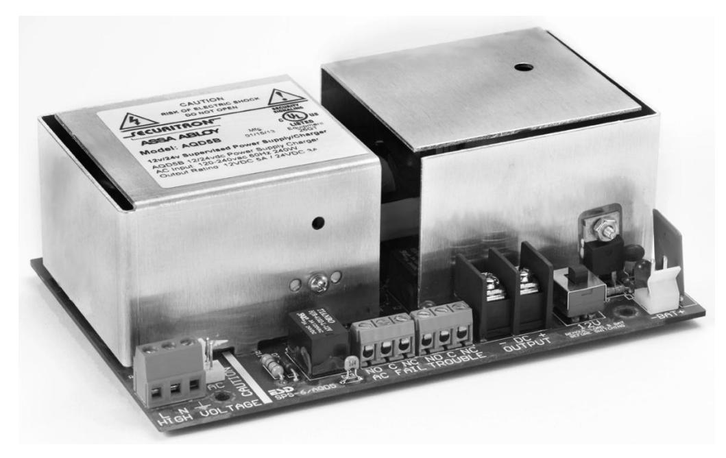
Overview of AQD5B Series Power Module
The Securitron AccuPower AQD5 offers clean, steady and accurate power output for peak performance of access control equipment plus flexibility unmatched by any power supply/battery charger on the market today.
- Universal AC input with brownout tolerance to 60VAC
- Tolerates and protects against input voltage fluctuations.
- External LED AC power indicator
- Form " C" contact for AC power fail notification
- Class 2 Power Limited DC output
- Dedicated voltage for battery charging even under full load
- Low battery disconnect prevents deep discharge of batteries
- PTC protection for Thermal Runaway and Current Overload Short Circuit and Reverse Battery protection will auto restart without removing load.
AQD5B and AQD5 provide a single Class 2 power limited output. The output can be divided into additional channels using any of the optional power distribution boards: PDB4, PDB8, PDB-8F8R, PDB-8C8R, PDB-8C1R or PDB-1R.
Applications
The AQD5 Series can be used with electrified access control equipment in conjunction with access control systems and fire/burglary systems including most electrified locking hardware and latches, card readers, keypads, electric strikes, REX and motion detectors and more.
Pre-Installation Survey
Before installing the AQD5 Series, the mounting location should be determined and assessed for the following:
- Availability of AC power service
- Protection from vandalism and tampering
- Sufficient clearance for air circulation and heat dispersal
CAUTION: Check with your local code inspectors to ensure your compliance with the National Electrical Code (ANSI/NFPA 70), (Canadian Electrical Code for Canada) or equivalent and any additional licensing and wiring requirements for your jurisdiction.
Page 2 P/N 500-30010
A. Installing the Power Module
1. Select mounting location so that AC input conduit can be aligned to maintain separation with DC power outputs.
Ensure unit is mounted with sufficient airflow to prevent heat buildup.
IMPORTANT: AC Power input is not power limited. AC lines must be enclosed in approved conduit. AC Input lines must be separated by at least ¼" from Class 2 power limited output wires.
Mark board mounting hole locations and drill. Install four 6-32x1/4 mounting screws appropriate for the mounting location, leaving enough hardware exposed to install standoffs. Install standoffs. Place star washer on any one of the three standoff locations corresponding to a mounting location on the board that has a metal ring.
Affix board to standoffs with provided metal screws.
IMPORTANT: User is responsible for observing all electrical and code requirement when installing in self-provided enclosure or mounting location.
B. Make Electrical Connections
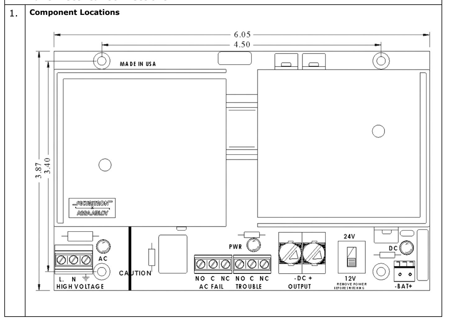
| 2. | Understanding the Power Module | ||||
|---|---|---|---|---|---|
|
Component
Label |
Component
Name |
Function | |||
| Fuse 6A/250V | AC Input Fuse |
6A/250V PTC fuse protects power module from AC line power
spikes. CAUTION: Fuse is not field replaceable |
|||
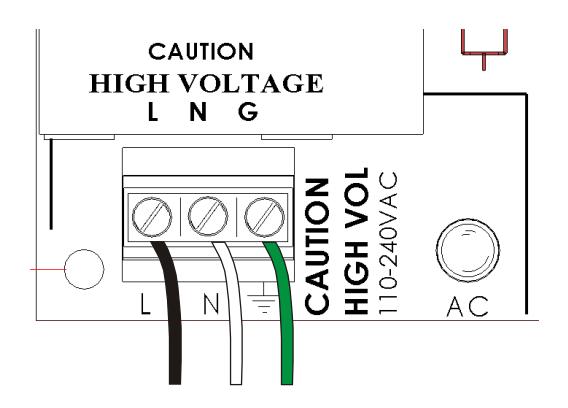
| LNG |
AC –In
Terminal Block |
A 3-wire terminal block for AC power input.
Handles 110-240 VAC. Accepts wire gauge 12AWG to 18AWG. L= Line (+) N=Neutral G=Ground |
|||
| AC LED |
AC Power
Indicator |
Green LED indicator is lit when AC power from AC circuit or
battery is ON. Indicator may be on board or on exterior of enclosure. |
|||
|
A 3-wire terminal block providing a SPDT-Form C contact that
changes state when the AC power is interrupted. Provides 2amp@120VAC output for triggering alert notification |
|||||
| AC FAIL | AC Status Relay |
NO = Normally Open
C = Common NC = Normally Close When energized switch is NO/C open, C/NC closed. During power loss, the switch changes state with NO/C closed and C/NC open. |
|||
|
A 3-wire terminal block providing a SPDT-Form C contact that
changes state when battery voltage drops to 12.1VDC/24.2VDC. Provides 2amp@120VAC output for triggering alert notification |
|||||
| TROUBLE | Low Battery Relay |
NO = Normally Open
C = Common NC = Normally Closed |
|||
|
The switch is NO/C open when energized, C/NC closed when
energized. During power loss, the switch changes state with NO/C closed and C/NC open. |
|||||
| PWR LED |
Battery Power
Indicator |
Green LED indicator is ON when AC or battery power is present.
OFF indicates AC fail with low or no battery power. |
|||
| -DC OUT+ |
DC-Out
Terminal Block |
A 2-wire terminal block for DC output voltage to devices, power
distribution or accessory board. DC output is Class 2 power limited and accepts 10AWG to 24AWG wire. |
|||
| 12V 24V | 12/24vdc switch | Toggle switch allows field selection of 12VDC or 24VDC output. | |||
| -BAT+ |
Battery Backup
Plug |
A 2-pin plug for connecting battery cables for uninterruptable
battery backup. |
|||
| DC LED |
DC Output Power
Indicator |
Red LED indicator is lit when DC power is ON. | |||
| +LTW |
Battery Limited
Time Warning |
2 position header providing an open collector output from the
negative position to annunciate low battery. Default position is Normally Open. Circuit closes to trigger a signal when battery falls to 95% depleted. Terminal accepts 22AWG to 30AWG wire. |
|||
3. Select Output Voltage
Determine voltage of devices that will be powered by the power supply unit. The AQD5 provides 5 amps continuous output at 12VDC or 3 amps @ 24 VDC.
To select voltage, slide switch in the direction of the desired voltage.
CAUTION: ENSURE AC POWER, BATTERY AND OUTPUT LOAD ARE DISCONNECTED BEFORE CHANGING SETTING . Ensure that the battery voltage matches the power supply output voltage before connecting batteries.
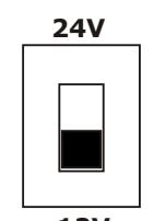
12V REMOVE POWER BEFORE SWITCHING
4. Make AC Power Input Connections
IMPORTANT: VERIFY AC POWER IS OFF BEFORE MAKING CONNECTIONS
Connect AC power wires as follows:
Black/Positive = L
White/Negative = N
Green/Ground= G
5. Make DC Power Output Connections to Distribution or Accessory Boards
Using 18 to 24 AWG wire, connect the DC OUT Positive (+) terminal to the positive (+) IN terminal on the distribution board.
Connect the DC OUT Negative (-) terminal to the Negative/Common/C (-) IN terminal on the distribution board.
It is recommended to pass the wires under the power module board before connecting to the accessory board in order to maintain separation from battery cables.
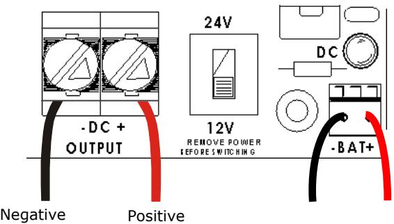
6. Make DC Power Output Connections to Devices
Insert wires into terminal block as indicated. Maintain separation from battery cable placement by at least 1/4".
Note: Use appropriate wire gauge for the Amperage and distance of the run.
For more info, see Wire Loss Calculator at
http://www.securitypower.com/AN2Wire.html
Connect the Positive wire to DC OUT Positive (+) terminal Connect the Negative wire to DC OUT Negative (-) terminal
7. Wiring for Status Monitoring Options
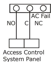
The diagram shows basic wiring to provide output to a control panel or local alarm for notification of AC power loss.
AC-ON state energized the NO/C switch.
The Switch changes state when power is lost.
Page 5 P/N 500-30010
8. Wiring for Limited Time Warning/Low Battery
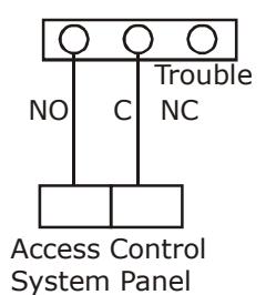
The diagram shows wiring to an access system controller to provide low battery warning.
The switch changes state from NO/C to C/NC when battery voltage drops to 12.1VDC or 24.2 VDC
9. Turn on AC Power
After making electric connections, turn on AC power before installing batteries.
C. Install Batteries
1. Understanding Battery Charging and Backup Power
The AQD5B is a backup battery charger with automatic fail over to battery power in case of primary AC power failure when batteries are installed and connected to the power module. The use of battery backup is optional—the unit will function without batteries installed, but no internal backup power will be available in case of AC power failure.
Note: The battery circuit features automatic disconnect when the battery output falls to 9.8 VDC/19.6 VDC to prevent deep discharge and also protects the power module in case the battery is connection is reversed.
IMPORTANT: Battery configuration must match the DC output voltage setting .
For battery backup in 12VDC operation, a single 12V battery may be used, or two (2) 12V batteries may be used wired in parallel for longer run time.
Backup power run time depends on the continuous output needed to support the load and the ambient temperature at the enclosure. Estimates are provided in the table below:
Estimated Standby Time (3 amp/5 minute reserve for alarm)
|
Total Output
Amps |
4Ah Battery
Standby |
7Ah Battery
Standby |
12Ah Battery
Standby |
24Ah
Standby |
40Ah
Standby |
|---|---|---|---|---|---|
| .5A | 5.5 Hrs | 12 Hrs | 20 Hrs | 40 Hrs | 65 Hrs |
| 1A | 2.5 Hrs | 5 Hrs | 9 Hrs | 19 Hrs | 32 Hrs |
| 1.3A | 2 Hrs | 4 Hrs | 7.2 Hrs | 15.5 Hrs | 24 Hrs |
| 2A | 1 Hrs | 2 Hrs | 5 Hrs | 10 Hrs | 15 Hrs |
| 3A | .5 Hrs | 1 Hrs | 3 Hrs | 6 Hrs | 9.5 Hrs |
| 4A | .5 Hrs | .8 Hrs | 2 Hrs | 4 Hrs | 8 Hrs |
| 5A | NA | .6 Hrs | 1.4 Hrs | 3 Hrs | 7 Hrs |
| 6A | NA | .4 Hrs | 1 Hrs | 2 Hrs | 4 Hrs |
Charge current is not less than 250mA @12VDC at peak load.
Page 6 P/N 500-30010
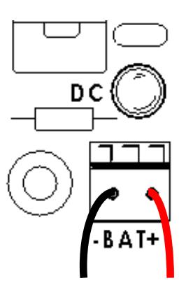
2. Connecting the Battery
Plug battery cable assembly into battery backup plug -BAT+ as shown.
Install batteries. Mark batteries with "Installed" date and "Replace By" date according to manufacturer's battery life recommendations.
Connect leads to batteries.
For 12VDC operation:
Connect red battery lead to the Positive (+) battery terminal. Connect black battery lead to the Negative (-) battery terminal.
For 24VDC operation:
Using Battery Jumper Cable, connect the Positive (+) battery terminal of one battery to the Negative (-) terminal of the second battery.
Connect red battery lead to the unused Positive (+) battery terminal. Connect black battery lead to the unused Negative (-) battery terminal.
Connect black battery lead to the unused Negative (-) battery
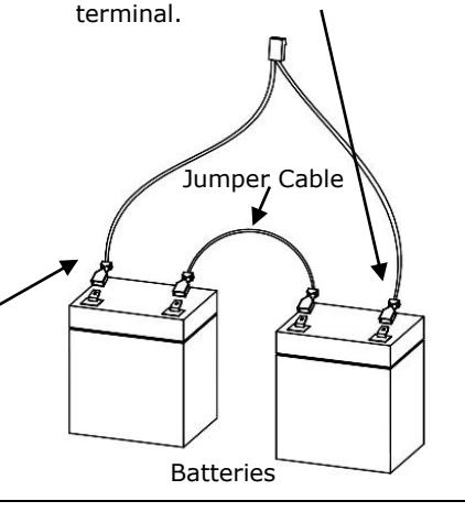
Connect red battery lead to the unused Positive (+) battery
| Recommended Annual Maintenance | |||
|---|---|---|---|
| Battery Test | Turn off AC power | ||
| Check DC output voltage under battery operation. | |||
|
For fully charged batteries, voltage should be above 11.5V. If voltage is below this range, test batteries
per battery manufacturer instructions and replace if needed. |
|||
| AC Fail Test |
Turn off AC power. AC Fail switch should trigger an alert upon disconnect or upon fail over to battery
power. |
||
Problems with installation? Call Securitron: 1-800-MAG-LOCK
For warranty information visit: www.securitron.com/en/site/securitron/About/MagnaCare-Warranty
Page 7 P/N 500-30010