Securakey SK-WLSE-MOD User Installation Manual
Open the original PDF document
View PDFSK-WLSE-MOD
USER/ INSTALLATION MANUAL
Wireless LAN Module for Use with SK-ACPE and SK-MRCP (NOVA.16) Access Control Panels

INTRODUCTION
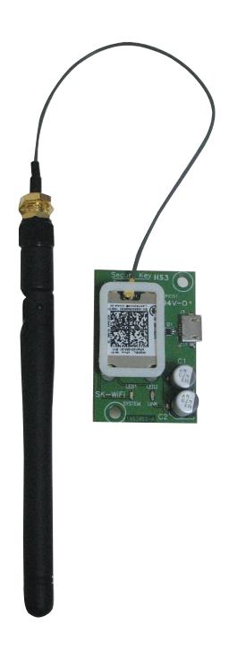
The SK-WLSE-MOD Wireless LAN Module is an accessory for the Secura Key SK-ACPE and SK-MRCP (NOVA.16) Access Control Panels, which allows the control panel to connect to the host system via an existing 802.11b/g Wireless Router. The SK-WLSE-MOD is based on the Lantronix xPico® Wi-Fi module, which is a complete device server suitable for mobile M2M applications. It can be configured from any mobile device, including smartphones and tablets, or a laptop.
Required Information
The SK-WLSE-MOD serial number is the MAC Address. This number is available on the label. Provide this number to the System Administrator.
Example: 0080A39805ED
The SK-WLSE-MOD must have a unique Static IP Address on your network. The System Administrator generally provides the IP address, Subnet Mask, Gateway and the SSID (Network Name). Write these down in the blank spaces below for future reference.
| IP Address | ||
|---|---|---|
| Subnet Mask | ||
| Gateway | ||
| SSID (Network Name): |
Physical Installation
-
1. Install the module component-side-up, lining up the screw holes on the module to those on the panel. The antenna wire should be located at the top of the board.
- a. On the SK-ACPE control panel, install the module at J12. The panel's firmware version must be 3.08 or higher, and the panel must be REV For higher (Rev. Label is located near the center of the circuit board.).
- b. On the SK-MRCP (NOVA.16) control panel, install the module at J6 The panel's firmware version must be 1.02 or higher, and the panel must be REV C or higher (Rev Label is located near the center of the circuit board).
- 2. Attach the antenna cable to the Wi-Fi module. Unscrew the antenna from the brass fitting at the end of the cable, and insert the threaded fitting up through the access hole in the control panel housing. Then, screw the antenna down over the threaded part.
- 3. Move the jumper JP1 (located at the top of the control panel circuit board) from pins 2 & 3 to 1 & 2 to enable the Wi-Fi module
- 4. Apply power to the control panel.
Accessing the xPico® Wi-Fi module configuration screen
- 1. By default, the SoftAP mode is enabled with a default SSID of XpicoWiFi_ xxxxxx, where xxxxxx are the last six characters of the unique xPico WI-Fi serial number (or the MAC address). For example if the serial number is 0080A398010E then the SSID would be xPicoWiFi_98010E.
- 2. A Wi-Fi enabled device is required to configure the SK-WLSE-MOD. You can use an Android or Apple (iOS) smart phone or tablet, or a laptop computer. Disconnect any other networks from the device you will be using to do the configuration.
- 3. On your mobile device, go to your Wi-Fi Settings, look for the SSID named XpicoWiFi_xxxxxx, then select and connect your device to it. The default security for the xPico WiFi SoftAP is WPA2 and the passphrase is XPICOWIFI (case sensitive).
- 4. Open a web browser such as Google Chrome, Mozilla Firefox, Apple Safari, or the latest version of Windows Internet Explorer (older versions may not work) and navigate to either xpicowifi.lantronix.com or 192.168.0.1. If you do not see the xPico menu, try a different browser.
- 5. When prompted enter the USERNAME = admin and the PASSWORD = PASSWORD to access the configuration and management web pages (both are case sensitive)
- 6. Now you will be able to view the web configuration screen.
Configuring the xPico® Wi-Fi module
Using the IP Address and other information from your Network System Administrator, complete the following steps:
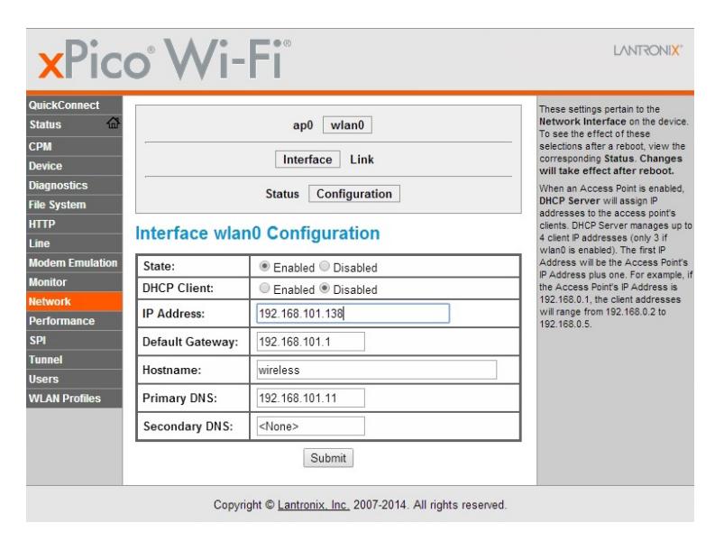
- 1. Select Network from the menu on the left side of the screen
- 2. Select wlan0, Interface, and Configuration
- 3. State = select Enabled
- 4. DHCP Client = select Disabled (this will create a static IP address)
- 5. IP Address = enter the Static IP Address assigned to the Wi-Fi module
- 6. Default Gateway = enter the IP Address of Gateway Server
- 7. Hostname = Hostname assigned to Wi-Fi Module (use the default/ displayed value)
- 8. Primary DNS = IP Address of DNS Server (use the default/displayed value)
- 9. Secondary DNS = IP address of backup DNS Server (if applicable, use the default/displayed value)
- 10. Click on the Submit button on the bottom to make changes
Saving Configuration and Rebooting
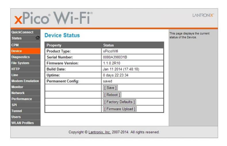
- 1. Select Device from the menu on the left side of the screen
- 2. Click on Save to save any changes made in the previous steps
- 3. Click on Reboot to reboot the Wi-Fi module and applies all changes.
Connecting to a Wireless Network
1. Select Quick Connect from the menu on the left side of the screen
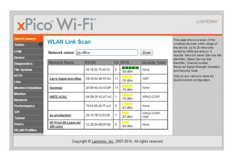
2. Click on the Network Name you want to connect to. If unavailable, enter the Network Name in the provided field, or click Scan and click on the Network Name
- 3. If security field appears, enter the Password of the Wireless Network
- 4. Click Apply and then OK to accept the warning prompt
- 5. Click Submit, then Accept the warning prompt again to make changes permanent
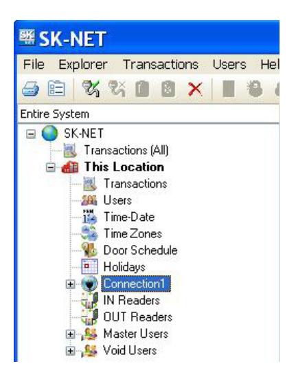
SK-NET Configuration
1. Right click on Connection 1 and select properties
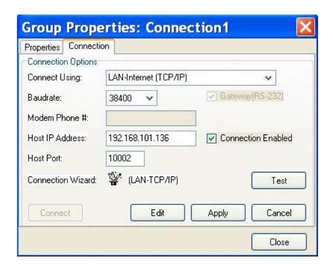
- 2. Select the Connection tab
- 3. Connect Using = Select LAN Internet (TCP/IP)
- 4. Baudrate = select 38400
- 5. Host IP Address = enter the Static IP Address you set up on the Wi-Fi module
- 6. Host Port = enter 10002
- 7. Select Apply and then click on Connect to establish a connection
INSTRUCTION TO THE USER xPico Wi-Fi FCC ID number: R68XPICOW
This equipment has been tested and found to comply with the limits for a Class B digital device, pursuant to Part 15 of the FCC Rules. These limits are designed to provide reasonable protection against harmful interference in a residential installation. This equipment generates, uses, and can radiate radio frequency energy and, if not installed and used in accordance with the instructions, may cause harmful interference to radio communications. However, there is no guarantee that interference will not occur in a particular installation. If this equipment does cause harmful interference to radio or television reception, which can be determined by turning the equipment off and on, the user is encouraged to try to correct the interference by one of the following measures:
- 1. Reorient or relocate the receiving antenna.
- 2. Increase the separation between the equipment and receiver.
- 3. Connect the equipment into an outlet on a circuit different from that to which the receiver is connected.
- 4. Consult the dealer or an experienced radio/TV technician for help.
This device complies with Part 15 of the FCC Rules. Operation is subject to the following two conditions: (1) This device may not cause harmful interference, and (2) this device must accept any interference received, including interference that may cause undesired operation


20301 NORDHOFF STREET • CHATSWORTH, CA 91311 PHONE (818) 882-0020 • FAX (818) 882-7052 TOLL-FREE (800) 891-0020 3321398 www.securakey.com • mail@securakey.com