Securakey Radio Key RK-65K KS Installation Instructions
Open the original PDF document
View PDFRADIO KEY® Installation Instructions
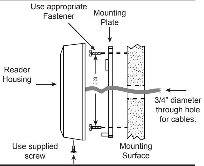
SWITCHPLATE INSTALLATION DIAGRAM
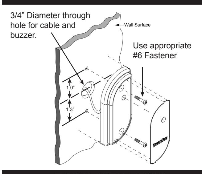
MULLION INSTALLATION DIAGRAM
INSTALLATION STEPS FOR RK-WS, RK65KS:
- 1. Drill holes as needed per installation diagram shown to the left.
- 2. Feed cable through 3/4" hole.
- 3. Attach the mounting plate to the mounting surface with the appropriate fasteners.
- 4. Attach the housing to the mounting plate by inserting the two tabs inside the top of the housing into the two slots at the top of the mounting plate.
- 5. Secure by installing supplied screws into the hole at the bottom of the reader.
- 6. Connect cable per wiring diagram shown below.
INSTALLATION STEPS FOR RK-WM, RK65K:
- 1. Drill holes as needed per installation diagram shown to the left.
- 2. Feed cable through 3/4" hole.
- 3. Attach reader to any flat surface with two #6 screws.
- 4. Snap label insert into front of reader to cover screws.
TYPICAL INSTALLATIONS STANDALONE READERS (RK-65K/RK65KS)
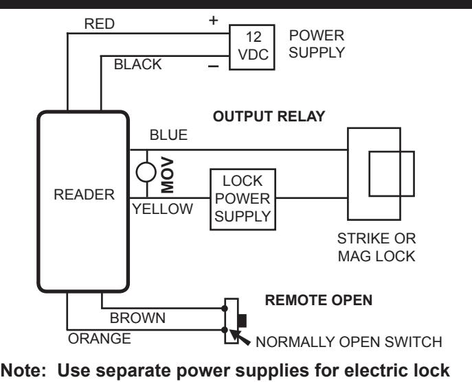
and for access control unit.
WIRING CONNECTIONS
| RK-65K & RK65KS | RK-WM & RK-WS | ||
|---|---|---|---|
|
WIRE
COLOR |
STANDALONE WIRING
CONNECTIONS |
WIEGAND OUTPUT
WIRING CONNECTIONS |
WIRING CONNECTIONS |
| RED | 5-14 VDC + | 5-14 VDC + | 5-14 VDC + |
| BLACK | GROUND | GROUND | GROUND |
| YELLOW | LATCH RELAY | NOT NEEDED | BUZZER INPUT (1) |
| BLUE | LATCH RELAY | NOT NEEDED | HOLD |
| ORANGE | REMOTE OPEN (2) | GREEN LED INPUT (3, 1) | GREEN LED INPUT (1) |
| BROWN | REMOTE OPEN (2) | RED LED INPUT (3, 1) | RED LED INPUT (1) |
| GREEN | NOT NEEDED | DATA-0 | WIEGAND DATA-0 |
| WHITE | NOT NEEDED | DATA-1 | WIEGAND DATA-1 |
( 1 ) C o n n e c t t o G R O U N D t o a c t i v a t e ( 2 ) I n p u t P r o g r a m m e d f o r R e m o t e O p e n ( 3 ) I n p u t P r o g r a m m e d f o r L E D / B e e p e r C o n t r o l
Parts Supplied:
Access Control Unit MOV (RK65K & RK65KS only) Operating Guide (RK65K & RK65KS only) Installation Instructions all Models Log Sheet (RK-65K only) Mounting Plate (RK-WS, RK65KS only) 2, #6 Mounting Screws 1, 4x40 Screw (RK-WS, RK65KS only) 1, Security Screw (RK-WS, RK65KS only) Snap-In Labels (RK65K only)
Accessories (not included):
RK600-PS: 9VDC plug-in power supply.
It is designed to power the RK-65K and RK-65KS
only, and requires 120 VAC input.
RK-BB: Back Box/Spacer (RK-WS & RK65KS) RK-HHP: Hand-Held Programmer (RK65K)
SK-SR SecuRelay™ - Smart relay module, DPDT.
SPECIFICATIONS:
POWER REQUIREMENTS
5-14 VDC, 90 mA
OUTPUTS
SPST Solid State Relay, 1A max. @60 VAC or DC Normally open or normally closed (field programmable (See Operating Guide). For RK-65K and RK-65KS only.
INPUTS
Default is Remote Open (requires contact closure).
For RK-65K and RK-65KS only.
Also programmable as Bicolor (Red or Green) LED Control or Buzzer/LED control for online systems (see Operating Guide).
WIEGAND OUTPUT
Any Wiegand Format up to 40 bits
Maximum Distance: 500 ft. - 5 or 6 conductor 20 gauge shielded cable
ENVIRONMENT
Access Control Unit, Key Tags and Cards
Ambient Temperature -40° to +70°C (-40° to +158°F) Humidity 0 to 95% (non-condensing)
INSTRUCTION TO THE USER FCC ID: NNHRK100M
This equipment has been tested and found to comply with the limits for a class B digital device, pursuant to part 15 of the FCC Rules. These limits are designed to provide reasonable protection against harmful interference in a residential installation. This equipment generates, uses and can radiate radio frequency energy and if not installed and used in accordance with the instructions, may cause harmful interference to radio communications. However, there is no guarantee that interference will not occur in a particular installation. If this equipment does cause harmful interference to radio or television reception, which can be determined by turning the equipment off and on, the user is encouraged to try to correct the interference by one or more or the following measures:
- Reorient or relocate the receiving antenna.
- Increase the separation between the equipment and receiver.
- Connect the equipment into an outlet of a circuit different from that to which the receiver is connected.
- Consult the dealer or an experienced radio/TV technician for help.
This equipment has been certified to comply with the limits for a class B computing device, pursuant to FCC Rules. In order to maintain compliance with FCC regulations, shielded cables must be used with this equipment. Operation with non-approved equipment or unshielded cables is likely to result in interference to radio and TV reception. The user is cautioned that changes and modifications made to the equipment without the approval of the manufacturer could void the user's authority to operate this equipment.

3059349
CONFORMS TO UL STD. 153 CERTIFIED TO CSA STD. C22.2 NO. 12
SECURA KEY Models: RK-WS/RK-WM RK-65KS/RK65K 5-14 VDC, 90 mA


20301 Nordhoff Street, Chatsworth, CA 91311 PHONE (818) 882-0020 • FAX (818) 882-7052 TOLL-FREE (800) 891-0020 www.securakey.com mail@securakey.com