Securakey RKDT-SA-M SA-S Installation Instructions
Open the original PDF document
View PDFRKDT-SA-M / RKDT-SA-S Installation Instructions
SWITCHPLATE INSTALLATION DIAGRAM
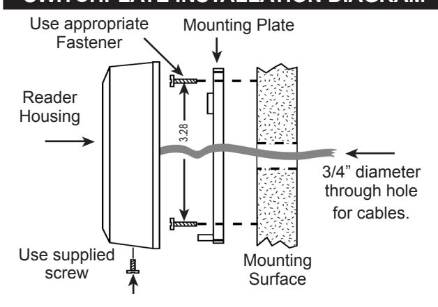
INSTALLATION STEPS FOR RKDT-SA-S:
- 1. If mounting the unit outdoors, especially on a rough surface like masonry, we recommend that you seal the reader with silicone caulking.
- 2. Drill holes as needed per installation diagram shown to the left or install a single gang j-box.
- 3. Run field wiring to reader location and feed into j-box or through cable hole.
- 4. Attach the mounting plate to the mounting surface or j-box with the appropriate fasteners.
- 5. Splice the connector pigtail to field wiring. Insert the connector into the back of the reader.
- 6. Attach the housing to the mounting plate by inserting the two tabs inside the top of the housing into the two slots at the top of the mounting plate.
3.20 ¿
.90"
3.14"
4.50
¿
¿ ¿
4.38"
1.74"
7. Secure by installing supplied screw into the hole at the bottom of the reader.
MULLION INSTALLATION DIAGRAM

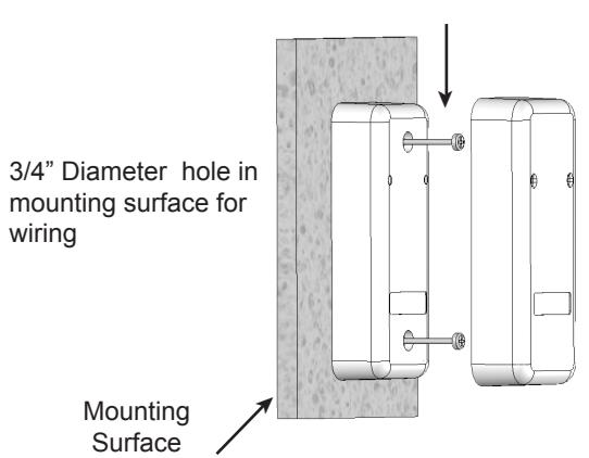
INSTALLATION STEPS FOR RKDT-SA-M
- 1. If mounting the unit outdoors, especially on a rough surface like masonry, we recommend that you seal the reader with silicone caulking.
- 2. Drill a hole for the field wiring. Remove decorative cover from reader. Using the reader as a template, mark the location of the two mounting holes. Drill two 1/8" pilot holes for the mounting screws. 4.38"
- 3. Run field wiring to reader location and feed through cable hole.
- 4. Splice the connector pigtail to field wiring. Insert the connector into the back of the reader.
- 5. Attach the reader to the surface using the two machine screws provided. These may be replaced with tamper proof screws (customer supplied).
- 6. Slip on the decorative cover (if used) until both tabs snap into place.
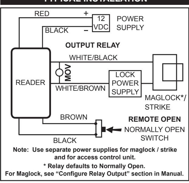
TYPICAL INSTALLATION

20301 Nordhoff Street, Chatsworth, CA 91311 PHONE (818) 882-0020 • FAX (818) 882-7052 TOLL-FREE (800) 891-0020
Website: www.securakey.com • E-mail: mail@securakey.com
| RKDT WIRING CONNECTIONS | ||
|---|---|---|
| WIRE COLOR | REMOTE OPEN STANDALONE | LED CONTROL WIEGAND |
| GREEN | DATA-0 | DATA-0 |
| WHITE | DATA-1 | DATA-1 |
| VIOLET | NOT USED | NOT USED |
| GRAY | NOT USED | NOT USED |
| ORANGE | NOT USED | GREEN LED INPUT (3, 1) |
| BROWN | REX LATCH + TIMER (2, 1) | RED LED INPUT (3, 1) |
| YELLOW | NOT USED | BEEPER INPUT (1) |
| BLUE | NOT USED | HOLD (1) |
| RED | 5-14 VDC + | 5-14 VDC + |
| BLACK | GROUND | GROUND |
| WHITE/BLACK | RELAY + | NOT USED |
| WHITE/BROWN | RELAY - | NOT USED |
| (1) Connect to GROUND to activate | ||
(1) Connect to GROUND to activate (2) Input Programmed for Remote Open (3) Input Programmed for LED/Beeper Control
SPECIFICATIONS:
POWER REQUIREMENTS
5-14 VDC, 150 mA Max.
OUTPUTS
SPST Solid State Relay, 1A max. @60 VAC or DC Normally open or normally closed (field programmable) (See Operating Guide).
INPUTS
Default is Remote Open (requires contact closure).
Also programmable as Red LED Control for online systems (see Operating Guide). Additional inputs for Green LED, Beeper and HOLD are available in Wiegand mode.
WIEGAND OUTPUT
Any Wiegand Format up to 40 bits
Maximum Distance: 500 ft. - 5 or 8 conductor 20 gauge shielded cable
ENVIRONMENT
Access Control Unit, Key Tags and Cards
Ambient Temperature -40° to +70°C (-40° to +158°F) Humidity 0 to 95% (non-condensing)
Parts Supplied:
Access Control Unit MOV Operating Guide Installation Instructions Log Sheet
2, #6 Mounting Screws Cable Assembly 1, 4x40 Screw Decorative Cover
1, Security Screw 1, Cable Assembly
RKDT-SA-S RKDT-SA-M
Mounting Plate 2, #6 Mounting Screws
Accessories (not included):
RK-HHP Hand-Held Programmer
RK-PS: 9VDC Plug-in Power Supply. It is designed to
power the RKDT-SA-M/SA-S. Requires 110 Volts
AC power.
SK-SR SecuRelay™ - Smart Relay Module DPDT.
INSTRUCTION TO THE USER FCC ID: NNHDTR1
"This device complies with Part 15 of the FCC rules. Operation is subject to the following two conditions: (1) this device may not cause harmful interference, and (2) this device must accept any interference received, including interference that may cause undesired operation."
This equipment has been certified to comply with the limits for a class B computing device, pursuant to FCC Rules. In order to maintain compliance with FCC regulations, shielded cables must be used with this equipment. Operation with non-approved equipment or unshielded cables is likely to result in interference to radio and TV reception. The user is cautioned that changes and modifications made to the equipment without the approval of the manufacturer could void the user's authority to operate this equipment.

20301 Nordhoff Street, Chatsworth, CA 91311 PHONE (818) 882-0020 • FAX (818) 882-7052 TOLL-FREE (800) 891-0020