Securakey RK600e Operating and Installation Guide
Open the original PDF document
View PDFRadio Key® RK-600e
Stand Alone Proximity Access Control System With Patented* Dynascan® Technology
Installation & Operating Guide

Radio Key® 600e Operating & Installation Guide
Table of Contents
| Introduction | . 1 |
|---|---|
| RK-PD1 Program Deck & RK-HHP Hand-Held Programmer | |
| Programming Radio Key® 600e | |
| Programming Hints | |
| Basic Operation | . 8 |
| System Configuration | . 9 |
| Wiring | |
| Power | 12 |
| Installation | 15 |
| Troubleshooting | 18 |
| Returning a Unit | |
| Ordering Additional Transponders | 18 |
| Warranty | 18 |
| Specifications | |
| FCC Certification | 20 |
| Illustrations | |
| Figure 1, RK600e Components | . 2 |
| Figure 2, MOV Wiring Diagram | |
| Figure 3, Wiring Diagram | |
| Figure 4, Basic Installation | 16 |
| Figure 5, Wall Mounting on Metal Surface with Optional Spacer | 17 |
| Figure 6, Post/Flange Mounting | 17 |
| Tables | |
| Table 1, Cable Types and Distances | 10 |
| Table 2, Connector P1 Color Coding | |
| Table 3, Connector P2 Color Coding | |

INTRODUCTION
The Radio Key® 600e is a programmable single-door access control system which controls access for up to 600 users. It can control an electric strike, magnetic lock, or gate operator, and has an additional input for an exit switch and output contacts for external alarm shunting. The major components are shown in Figure 1.
The RK600e Access Control Unit contains the CPU, memory, access relay, and an internal reader. It has a beeper, and a bi-color LED indicator. An RK-HHP Hand-held Programmer or the RK-PD1 Program Deck (not included), is used to add or delete transponders, to set the operating mode, to program the password and latch timer. The RK600e is weather resistant and is provided with a gasket for exterior installation.
Parts Supplied:
Access Control Unit
Gasket
MOV
Mounting Plate
Connector/Wire Pigtail
Operating Manual
Quick Start Guide and Wallet Sized Guide
User Log Form
2, 6-32 x 1/2" mounting screws
1, 4-40 x 5/16" Phillips housing screw
1, 4-40 x 5/16" Hex Socket, security housing screw
The RKAR Auxiliary Reader is optional, but recommended for extreme weather or higher security applications. This reader parallels the internal reader in the RK600e. It contains a bi-color LED indicator and a beeper also driven by the RK600e. A gasket is provided for exterior installation.
The RKAT Audit Trail Module is optional and allows the RK600e to connect to a PC or Printer for Audit Trail Reporting and programming. RK-LINKTM Software for Windows® is included.
RK-PS, a 12VDC plug-in power supply is optional. It is designed to power the RK600e only, and requires 120 VAC input. RK600-BB Back Box / Spacer is optional. It extends the RK600e out from the mounting surface and provides additional room for wiring.
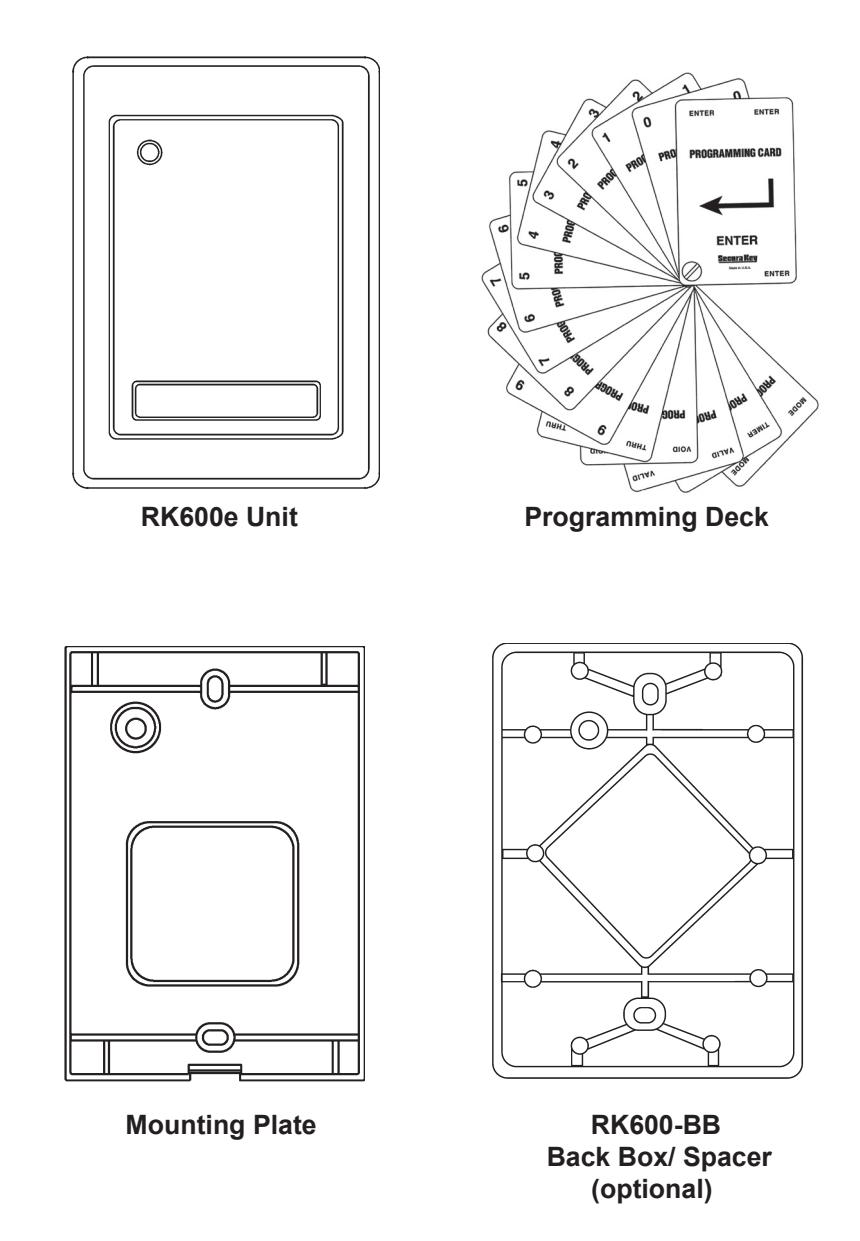
Figure 1 - RK600e Components
PROGRAMMING RADIO KEY® 600e
Radio Key® Transponders (Key Tags) are pre-encoded and engraved at the factory with unique Transponder ID numbers. Because these numbers are unique, Facility Codes (Site Codes) are not required.
Transponder ID Numbers are not pre-programmed into the Radio Key<sup>®</sup> 600E; you must add them to the system as described below.
Radio Key 600E allows you to assign a Transponder to each User Number (1 - 600) for programming purposes. The User Number is associated with the individual person using the transponder.
Be sure to record the User Number, the Transponder ID Number and the user's name, and keep this information in a secure place. A blank User Log Form has been included for this purpose. Do not write on this form; use it as a photocopy master.
Because a new Transponder ID Number can be assigned to any available User Number, the reader always has capacity to store 600 Transponders, even after many Transponders have been voided from the reader.
The Program Deck & Hand-Held Programmer
The RK-PD1 Program Deck or the RK-HHP are used to program your Radio Key® 600e. Presenting program cards to the Radio Key® RK-600e is equivalent to pressing keys on the RK-HHP hand-held programmer. The RK-PD1 consists of the 16 following cards:
FNTFR "0" ZERO "1" ONE "2" TWO "3" THREE "4" FOUR "5" FIVE "6" SIX "7" SEVEN "8" EIGHT NINE THRU VAL ID VOID SET TIMER
MODE
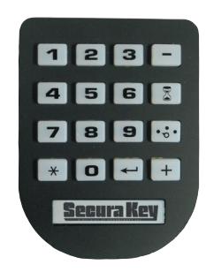
Hand-Held Programmer (RK-HHP)
Presenting these cards to the RK-600e is equivalent to pressing keys on a Keypad or key board. As you present program cards to the unit, it will chirp to indicate that it has read the card. The next sections of this manual explain what program card sequences to use to perform the various program functions.
PROGRAMMING STEPS
To program the Radio Key® 600e, you must first enter the program mode as described in the next section below. Once in the program mode, the LED will blink amber as an indicator. The unit will remain in the program mode until it is put into another mode. Also, if a program card is not presented for 15 seconds, the unit will return to the active mode.
After you have completed a proper program sequence, the unit will beep and the LED will flash green to indicate that the program instruction has been accepted. A red light and three beeps at the end of a programming sequence means that you have made an error. Refer to the appropriate section, and carefully re-enter the command in the proper sequence.
If you select a User Number for a new Transponder, and a Transponder ID Number has already been stored in memory for that User Number, a red light and three beeps will occur. Select another User Number or void the User Number, which removes the previously stored Transponder ID from memory.
NOTE: User Number and ID Number Values in the following examples are for demonstration purposes only; enter the appropriate values for your system.
To Enter Program Mode:
Present Program cards to the unit in the sequence that represents the password and then present the "ENTER" card. (All new units are preprogrammed with the password 12345.) The LED will flash amber to show that the unit is in Program Mode. The unit will "time out" and return to Active (Normal) Mode in 15 seconds if no Program card is presented.
(Password) (ENTER) 1 + 2 + 3 + 4 + 5 +
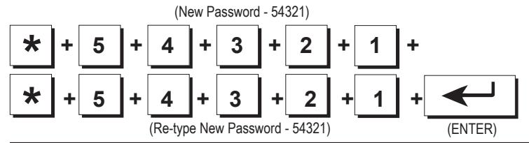
Change your Password:
Put the unit into the Program mode, if necessary (see above). Present the THRU Card to the unit. Then present the sequence of program cards representing the desired new password (exactly 5 digits) to the unit. Then present the THRU Card. Again present the sequence of program cards representing the desired new password to the unit. Present the ENTER card to the unit. A green light and beep means that the Password was changed. Note that 12345 is the default (factory) password; use another number sequence for best security.
Add a Transponder (Key Tag) to the System:
Put the unit into the Program mode, if necessary (see above). Present the ADD card to the unit and then present the sequence of program cards representing the desired User Number (1-600) to the unit. Then present the ENTER card to the unit. Hold the Transponder near the RK600e Unit. A green light and beep means that the Transponder was accepted. A red light and three beeps means a Transponder has already been stored for the selected User Number. Delete the previously stored Transponder or select a new User Number.
(ADD) (User Number 12) (ENTER) + 1 + 2 + (Hold Key Tag near unit)
Add a Transponder by Entering the Transponder ID:
Instead of presenting the transponder, you can also use the Program Deck to enter the Transponder ID number: Put the unit into the Program mode, if necessary (see above). Present the ADD card to the unit and then present the sequence of program cards representing the desired User Number (1 - 600) to the unit. Present the THRU Card. Present the sequence of program cards representing the ID number printed on the Transponder. Then present the ENTER card.
(ADD) (User Number 12) (ID Number 995) (ENTER) + 1 + 2 + * + 9 + 9 + 5 +
Record the User Number and Transponder ID Number in the User Log Form.
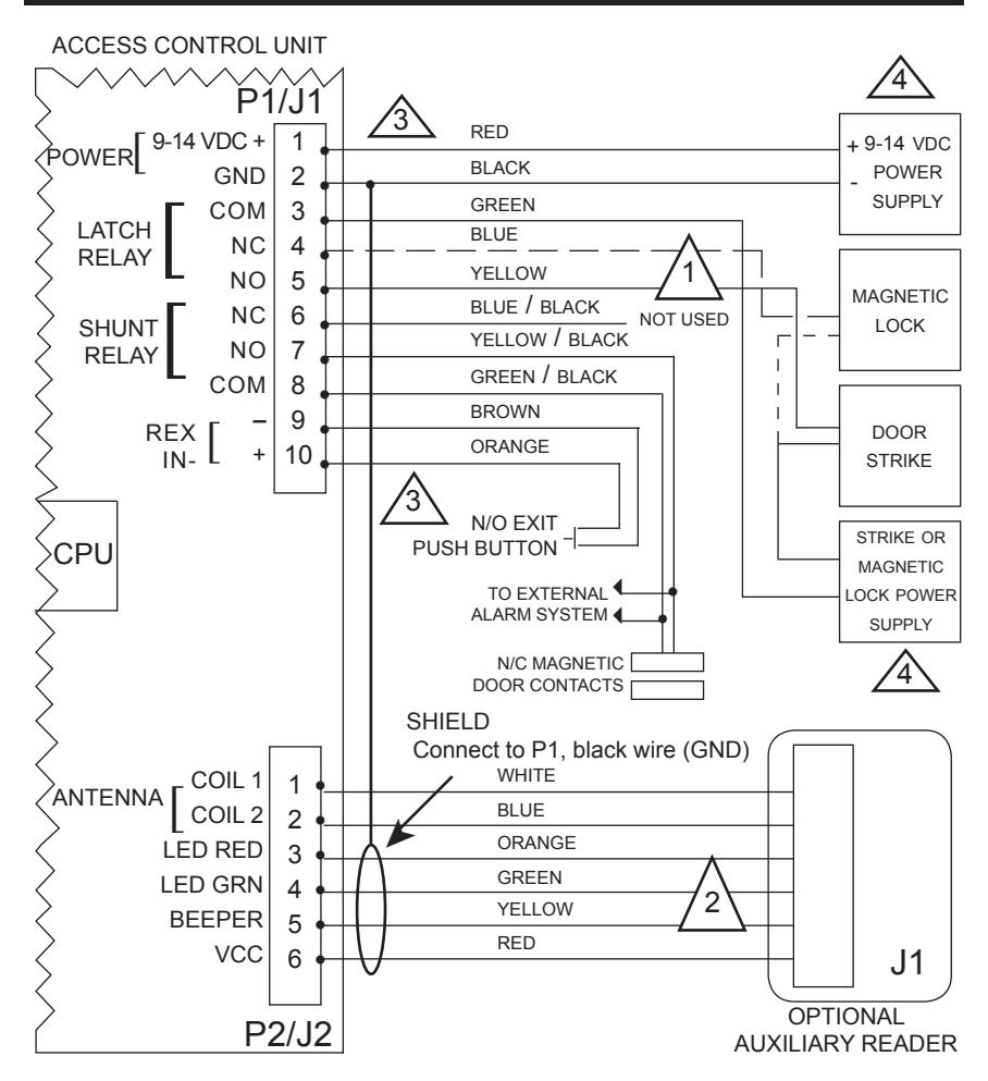
Add a Series of Transponders to the System:
Put the unit into the Program mode, if necessary (see above). Present the ADD card to the unit and then present the sequence of program cards representing the desired starting User Number to the unit. Present the THRU Card. Then present the sequence of program cards representing the desired ending User Number. Present the THRU card, then present the ENTER Card. Present the Transponders to the reader in the desired order (making a careful record of which transponders are assigned to which User Numbers). If one or more Transponders are already entered into the User Number range you have selected, a red light and three beeps will occur, in which case, you must delete the entire range (see below) before proceeding.
Delete a Transponder from the System:
Put the unit into the Program mode, if necessary (see above). Present the VOID card to the unit and then present the sequence of program cards representing the desired User Number (1 - 600) to the unit. Then present the ENTER Card to the unit. A green light and beep means that the Transponder was deleted.
(User Number 12) (ENTER) (VOID) + 1 + 2 +
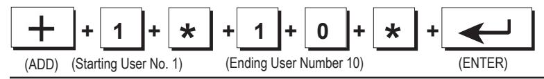
Delete a Range of Transponders from System:
Put the unit into the Program mode, if necessary (see above). Present the VOID card to the unit and then present the sequence of program cards representing the desired starting User Number to the unit. Present the THRU Card. Then present the sequence of program cards representing the desired ending User Number. Then present the ENTER Card . A green light and beep means that the range of Transponders was deleted.
(VOID) (Starting User No. 1) (Ending User Number 10) (ENTER) + 1 + * + 1 + 0 +
Delete a Transponder by Presenting to Reader:
Put the unit into the Program mode, if necessary (see above). Present the VOID card to the unit. Then present the ENTER Card to the unit. Hold the Transponder near the RK600e Unit. A green light and beep means that the Transponder was deleted.
Delete a Transponder by Entering Transponder ID:
Put the unit into the Program mode, if necessary (see above). Present the VOID card to the unit. Present the THRU Card. Then present the sequence of program cards representing the ID number printed on the Transponder. Then present the ENTER card. A green light and beep means that the transponder was deleted.
(VOID) (ID Number 995) (ENTER) + * + 9 + 9 + 5 +
Set the Latch Timer:
Put the unit into the Program mode, if necessary (see above). Present the SET TIMER Card to the unit. Then present the sequence of program cards representing the desired Latch Time (0 - 30 seconds) to the unit. Present the ENTER card. A green light and beep means that the Latch Timer setting was changed. If you set the Latch Timer for "0" seconds, the actual latch time will be approximately 0.25 seconds.
(SET TIMER) (5 Seconds) (ENTER) + 5 +
Set the Operating Mode:
Put the unit into the Program mode, if necessary (see above). Present the MODE Card to the unit. Then present either the "1" , "2", or "3" card to the unit. Present the ENTER card. The Access Control Unit will exit Programming Mode and enter the selected Mode. Selections are:
- 1. Active (Normal) -- LED is Off
- 2. Inactive (Locked) -- LED blinks Red
- 3. Door Unlocked -- LED blinks Green

To Exit Programming Mode Immediately:
Present the MODE Card to the unit. Then present the "1" card to the unit. Present the ENTER card. This returns the unit to normal mode immediately, bypassing the 15 second timeout.
(MODE) (ENTER) + 1 +
PROGRAMMING HINTS
Password
If the password is lost or forgotten it can be restored to the factory default (12345). Remove the RK600e unit from the mounting plate, disconnect power (unplug the connector from J1 or disconnect the DC power supply) press and HOLD the reset switch (SW1, on the reader circuit board), restore power, then release the switch. Note that this will also reset the latch timer to one second and operating mode to active.
Adding the Same Transponder More Than Once
If you add the same Transponder to the system more than once, the Transponder ID will be deleted from the previous User Number position and added to the newest User Number position.
Setting the Latch Timer
The latch timer controls the latch relay, which has two sets of contacts; one for unlocking the door or gate, and one for bypassing an external alarm system. The factory preset latch time is 1 second but it can be changed to any value from 1-30 seconds. If the latch timer is set to 0 seconds, this pulses the latch relay for 0.25 second, sufficient for most electric turnstiles. The beeper and LED are always fixed at one second.
Setting the Operating Mode
Three operating modes are possible. For normal operation select Mode 1; to temporarily lock out all transponders, select Mode 2; to hold the door open continuously select Mode 3.
BASIC OPERATION
To use a Key Tag with Radio Key® 600E, simply hold your Radio Key® Transponder near the RK600e Unit or optional Auxiliary Reader. The RK600e Unit or Auxiliary Reader generates an RF field, which causes the Key Tag to transmit a unique Transponder ID Number back to the Auxiliary Reader or RK600e Unit.
If the Transponder ID Number is stored in memory, the latch relay is activated, unlocking the controlled door or gate and shunting any external alarms. A green light and a beep indicates that access is granted.
If the Transponder ID Number is not stored in memory, the door or gate remains locked and a red light and three rapid beeps indicate that access is denied. Otherwise the LED is normally off.
NOTE: If five incorrect passwords are entered, the unit will sound an alarm and display a red LED for 30 seconds, then return to normal mode.
SYSTEM CONFIGURATION
RK600e Unit Only
Locate on the exterior wall, near the latch side of the controlled door. Height should be 36" - 48" (check local codes). Use weather gasket (supplied) for outdoor installations.
RK600e Unit with Optional Auxiliary Reader
Auxiliary Reader - Locate on the exterior wall, near the latch side of the controlled door. Height should be 36" - 48" (check local codes).
RK600e Unit - Locate inside the secure area. For use as an exit reader, mount the RK600e Unit on the interior wall at the same relative location as the Auxiliary Reader but not directly behind it. For best reading distance, offset the RK600e Unit and Auxiliary Reader by about 6". Otherwise, the RK600e Unit can be mounted up to 30 cable feet away from the Auxiliary Reader.
Metal Surfaces - Effect on Reading Distance
Normally, Radio Key® 600E will read Key Tags at up to 6". However, when the RK600e Unit or optional Auxiliary Reader is mounted directly on a metal surface, the reading distance decreases slightly. To reduce this effect, install the Spacer (optional) between the mounting surface and the mounting plate; this will restore most of the reading distance.
Vehicle Gate Applications
Optional Auxiliary Reader - Locate 8 - 12 feet in front of gate on driver's side. A Post Mount Adapter or Flange Mount Adapter is available for post mounting. Install the optional Spacer between the mounting adapter and Auxiliary Reader to reduce the effect on reading distance caused by the metal mounting adapter. Alternatively, the RK600e can be used alone, post mounted with weather gaskets.
RK600e Unit - Locate in nearby building, guard house or water-tight (NEMA) enclosure up to 30 cable feet from Auxiliary Reader. For metallic NEMA enclosures, install the optional Spacer between the enclosure wall and RK600e to reduce the effect on reading distance caused by metal. Locate the RK600e in the center of the NEMA enclosure. Non-metallic NEMA boxes will have no effect on reading distance.
Concealed Installation
The optional Auxiliary Reader can be mounted behind any non-metallic wall surface, (glass, wood paneling, plastic, drywall). The reading distance may be affected slightly by metal framework or structural material in the wall.
WIRING
Run the following cables to the RK600e Unit location. Conduit is recommended to reduce the effects of EMI/RFI and for physical protection of the wires.
| Table 1 - Cable Types and Distances | |||||
|---|---|---|---|---|---|
| Wire Application | Cable Type | Description | |||
| From Power Supply | 2-cond, 18-22 AWG | n/a | |||
|
From Locking Device
and power supply or gate operator |
2-cond. See Mfr's
Specifications |
n/a | |||
|
From external alarm
system's Door Monitor Switch (for shunting) |
2-cond, 18-22 AWG | 250 feet | |||
| From Exit Button or PIR | 2-cond, 18-22 AWG | 250 feet | |||
|
From Optional Auxiliary
Reader |
2-cond unshielded 22
AWG, plus a separate 4-cond, shielded 22- 24 AWG cable |
30 feet | |||
RK600e Wire Connections
The RK600e Unit is supplied with a pre-wired connector (P1) with colorcoded wire leads. Referring to Table 2, Connector P1 Color Coding and Figure 2, Wiring Diagram, make all appropriate connections from Connector P1 to the power supply, locking device or gate controller, external alarm circuit and Request-to-Exit (REX) input. Use solder and tape or gel-filled crimp-on connectors.
Note: Max relay power rating with resistive load is 2A@24V DC or AC; 0.5A@115VAC. Use an interposing relay to switch greater loads.
The RK600e does not supply power to operate electric strike or magnetic locks - a separate supply is required. Refer to strike/ magnetic lock manufacturers instructions.
Users can request to exit through the controlled door without using a transponder (and without causing an alarm condition), by pressing an Exit button or triggering the relay output of an Exit PIR connected to the RK600e Unit. This will operate the latch relay for the programmed latch time.
When wiring the REX Input, connect the brown wire to one side of the REX switch contact and connect the other side of the switch to the orange wire. This input must be a dry contact, with no voltage present.
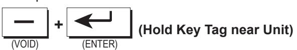
Use a Separate Power Supply for Electric Locks
The access control unit and the electric locking device should be connected to separate power supplies. Install the MOV provided as shown below:
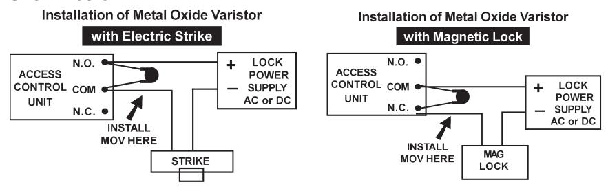
Figure 2 - MOV Wiring Diagram
Auxiliary Reader Wire Connections
A short cable assembly extends from the back of the Optional Auxiliary Reader. Connect Plug P2 at the end of the cable to Socket J2 at the RK600e Unit. If the cable must be extended, for the best performance, use TWO SEPARATE CABLES: one unshielded, non-twisted, two-conductor wire to the antenna coil (Pins 1 & 2), plus a SEPARATE 4-conductor shielded cable to the LED and Beeper (Pins 3 - 6). These cables can be run in the same conduit. Connect the cable shield from the LED/Beeper cable to the black wire (GND) on P1 at the RK600e.
Route the auxiliary reader cable at least two feet away from sources of EMI (electro-magnetic interference), such as radio transmitters, elevators, large electric motors or fluorescent light ballasts.
WARNING
Use of any Auxiliary Reader cable which combines all conductors inside one shield and/or uses twisted pair for the antenna lines will result in severely reduced reading distance. Failure to properly ground the cable shield for the LED/Beeper lines will also result in severely reduced reading distance.
Note: When power is applied to the RK600e, the unit is calibrated for the current antenna configuration. Always connect the Auxiliary Reader first, before applying power to the RK600e.
Surface-Mounted Wiring
For installations where it is necessary to run cable along the wall surface (such as in a wall-mounted modular raceway) small break-away knockouts are provided on the bottom of the RK600e and Auxiliary Reader housings, as well as on the Spacer. Remove the knockouts with small pliers, and butt the raceway up against the opening in the housing to conceal the cable.
Power
The RK600e can be powered by the optional RK-PS 12VDC power supply, which is rated for powering the RK600e only. Alternatively, use any good 9-14 VDC supply which provides at least 150mA. DC power should be clean and filtered with no more than 1 VAC ripple (Peak to Peak). Do not run AC power in the same cable with DC power to the reader.
RK600e also has protection against accidental polarity reversal or use of low voltage AC.
WARNING
RK600e will not operate on AC Voltage or with DC polarity reversed.
1
SOLID LINE FOR ELECTRIC STRIKE OR OTHER FAIL-SECURE LOCKING DEVICE; DASHED LINE FOR MAGNETIC LOCK OR OTHER FAIL-SAFE LOCKING DEVICE.

USE SHIELDED CABLE FOR J2, PINS 3 - 6, AND UNSHIELDED, NON-TWISTED SEPARATE CABLE FOR PINS 1 & 2 (SUCH AS "ZIP CORD", LAMP COARD OR SPEAKER WIRE)

USE UNSHIELDED CABLE 18-22AWG FOR PINS 1-10
4
NOTE: IF COMMON POWER SUPPLY IS USED FOR BOTH THE RK600 AND ELECTRONIC DOOR LOCK, BE SURE TO INSTALL THE MOV WHICH IS PROVIDED WITH THE ACCESS CONTROL UNIT.
Figure 3 - Wiring Diagram
| Table 2 - Connector P1 Color Coding | ||||
|---|---|---|---|---|
| Wire Application | Wire | Color | Description | |
| Power Input | 1 | Red | +9 to 14 VDC | |
| 2 | Black | DC Power Ground | ||
| Strike/Operator Relay | 3 | Green | Latch, Common | |
| 4 | Blue | Latch, Normally Closed | ||
| 5 | Yellow | Latch Normally Open | ||
| Alarm Shunt Relay | 6 | Blue/Black | Shunt, Normally Closed | |
| 7 | Yellow/Black | Shunt, Normally Open | ||
| 8 | Green/Black | Shunt Common | ||
| REX | 9 | Brown | REX Input | |
| 10 | Orange | REX Input | ||
| Table 3 - Connector P2 Color Coding | |||||
|---|---|---|---|---|---|
| Wire Application | Wire | Color | Description | ||
| Antenna | 1 | White | Coil 1 | ||
| 2 | Blue | Coil 2 | |||
| LED Control | 3 | Orange | LED, Red | ||
| 4 | Green | Led, Green | |||
| Beeper | 5 | Yellow | Beeper Control | ||
| 6 | Red | VCC | |||
| Shield/ Drain Wire | n/a | Bare Wire | Connect to J1, Pin 2 | ||
INSTALLING THE UNITS
Installation Hints
Each unit (RK600e Unit or Auxiliary Reader) consists of two parts: a mounting plate and a housing. The Back Box / Spacer is optional.
When mounting the unit on metal, install the optional Back Box / Spacer (Figure 5) between the mounting plate and the mounting surface to minimize the loss of reading distance caused by the metal. The spacer can also be used on non-metallic surfaces to provide additional room for wiring connections.
When mounting the RK600e Unit and Auxiliary Reader on opposite sides of a wall, offset the units by about 6" for the best reading distance. Do not locate two RK600e units closer than two (2) feet apart. Do not locate the RK600e or RKAR within two (2) feet of a PC Monitor or CPU enclosure, or any other source of EMI (electro-magnetic interference) such as radio transmitters, elevators, large electric motors or fluorescent ballasts.
If the RK600e or Auxiliary Reader must be concealed, the RK-GM glass mount kit can be used to permanently adhere the unit to the back of a glass window. The RK-GM consists of two parts: a large PVC sheet which adheres to the inside of the window, and a smaller adhesive sheet that is used to affix the RK600e mounting plate to the larger sheet. To allow cables to exit the reader housing, remove the small knockout(s) on the bottom of the housing by prying out with small pliers.
Installation Procedure
- 1. Orient the mounting plate with the threaded insert at the bottom; attach it to a single-gang electrical box with two 6-32 x 1/2" screws (supplied); or attach directly to the wall surface, using anchor screws or toggle bolts (Figure 4).
- a. If using the optional spacer, insert spacer alignment pins into corresponding holes on the back of the mounting plate, then install both parts so that the spacer is closest to the wall or mounting surface (Figure 5).
- b. For exterior applications, install the thick gasket between the wall or mounting surface and the back of the mounting plate.
- c. If using the optional spacer, install the thick gasket between the spacer and the mounting surface, install the mounting plate and spacer using the two 6-32 x 1-1/2" screws supplied with the spacer, then place the thin gasket around the mounting plate (Figure 6).
- 2. Pull cable ends through the access hole in the mounting plate:
- a. If using the Auxiliary Reader, connect Plug P2 at the cable end to Socket J2 at the RK600e Unit, grounding the shield at the RK600e Unit end only. The Auxiliary Reader must be connected before power is applied to the RK600e.
- b. Connect Plug P1 to Socket J1 on the RK600e Unit circuit board.
- 3. Attach the housing to the mounting plate:
- a. Hold the bottom end of the housing away from the mounting plate.
- b. Insert the two tabs (inside top of housing) into the two slots at the top of the mounting plate.
- c. Swing the bottom of the housing toward the mounting plate.
- d. Secure by installing the 4-40 x 5/16" Philips screw (supplied) into the hole at the bottom. The 4-40 x 5/16" Hex Socket tamper-proof screw (supplied) can be substituted for additional security. The optional security tool (ST-2) is required in order to use the tamperproof screw.
- 4. Apply power. The LED will flash once and the beeper will sound. Refer to beginning of this manual for programming and operating instructions.
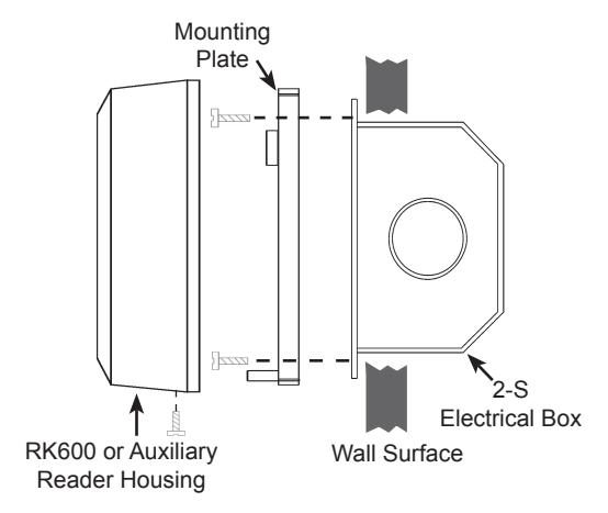
Figure 4 - Basic Installation
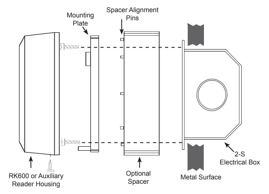
Figure 5 - Wall Mounting on Metal Surface with Optional Spacer
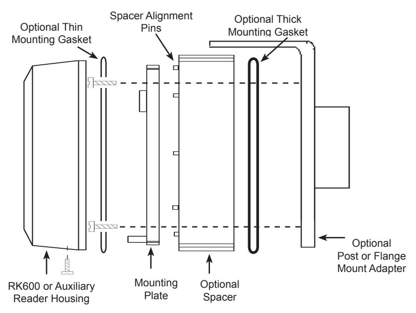
Figure 6 - Post/Flange Mounting
Troubleshooting
If your unit does not appear to be working, first check to see if the RK600e is getting 9-14 VDC power and that the polarity is correct. The unit should make a clicking sound when any key on the keypad is depressed. If you remove and restore power, the unit should beep once and the LED should flash Amber once.
Returning a Unit
If you believe you have a defective unit, please contact the dealer or distributor who sold you the unit. All service and repairs must be done through an authorized dealer or distributor.
Ordering Additional Transponders
If you need additional Transponders, please contact the dealer who sold you the Radio Key® 600E unit. Because Radio Key® transponders are uniquely encoded and do not use facility codes, you can buy them off-the-shelf from any Secura Key dealer. If you do not know who your dealer is, call Secura Key and we will recommend one near you.
WARRANTY (U.S. and Canadian)
"Secura Key products are warranted against defects in materials and workmanship for LIFE. Secura Key will replace any Secura Key manufactured product, except cards or tags, returned to us freight prepaid within the warranty period. This warranty does not include freight, taxes, duties, or installation expenses. THE WARRANTY SET FORTH ABOVE IS EXCLUSIVE AND NO OTHER WARRANTY, WHETHER WRITTEN OR ORAL, IS EXPRESSED OR IMPLIED. SECURA KEY SPECIFICALLY DISCLAIMS ANY IMPLIED WARRANTIES OR MERCHANTABILITY AND FITNESS FOR A PARTICULAR PURPOSE. The remedies provided herein are the buyers' sole and exclusive remedies. In no event shall Secura Key be liable for direct, indirect, special, incidental or consequential damages (including loss of profits), whether based on contract, tort or any other legal theory." Contact Secura Key for Export Warranty Policy.
SPECIFICATIONS
Models
RK600e Control Unit
RKAR Auxiliary Reader with Cable
Physical
| Access | ||||
|---|---|---|---|---|
| Control Unit | Auxiliary Reader | |||
| Depth | 0.84" (2.13 cm) | 0.84" (2.13 cm) | ||
| Width | 3.20" (8.12 cm) | 3.20" (8.12 cm) | ||
| Height | 4.5" (11.43 cm) | 4.5" (11.43 cm) | ||
| Weight | 4.7 oz (133.2 gm) | 7.0 oz (198.5 gm) | ||
| Material | Lexan® | Lexan® | ||
| Color | Beige | Beige | ||
Power Requirements
9-14VDC, 50mA avg, 150mA Peak
Communications
With Optional RKAT Audit Trail Module, allows connection of PC or Serial Printer (See RKAT data sheet for specifications)
Outputs
Latch & Shunt DPDT contact, 0.5A max@250 VAC or 2A max@24 VAC or DC
Input
Request to Exit Requires SPST contact closure
Environment
Access Control Unit
Ambient Temperature -40° to +70° C (-40° to +158° F) Humidity 0% to 95% non-condensing
Auxiliary Reader
Ambient Temperature -40° to +70° C (-40° to +158° F)
Humidity 0% to 100%
Operational
Reading Distance Up to 6" (15.24 cm)
User Capacity 600 key tags or cards (random numbered)
Key Tag Operation Passive Transmit Frequency 125 kHz Memory Non-Volatile
Latch/Alarm Shunt Timer Programmable 0.25 - 30 Seconds
Auxiliary Reader Cable 30' (10m) max. from Control Unit to Auxiliary Reader
2 conductor, non-twisted, non-shielded
and 4 conductor shielded
Accessories
RK-PD1 Proximity Programming Deck RK-HHP Handheld Programmer
RK-PS 12VDC, 500 mA, plug-in Power Supply, 120 VAC Input.
For Access Unit Only.
RK600-BB Back Box / Spacer - Beige, Lexan®.
RK-GM Glass Mount Adaptor
This product complies with UL 294 Standards, CE (European Standards) and with the limits for a Class B digital device, pursuant to part 15 of the FCC Rules.
FCC ID: NNHRK600
INSTRUCTION TO THE USER
This equipment has been tested and found to comply with the limits for a class B digital device, pursuant to part 15 of the FCC Rules. These limits are designed to provide reasonable protection against harmful interference in a residential installation. This equipment generates, uses and can radiate radio frequency energy and if not installed and used in accordance with the instructions, may cause harmful interference to radio communications. However, there is no guarantee that interference will not occur in a particular installation. If this equipment does cause harmful interference to radio or television reception, which can be determined by turning the equipment off and on, the user is encouraged to try to correct the interference by one or more or the following measures:
- Reorient or relocate the receiving antenna.
- Increase the separation between the equipment and receiver.
- Connect the equipment into an outlet of a circuit different from that to which the receiver is connected.
- Consult the dealer or an experienced radio/TV technician for help.
This equipment has been certified to comply with the limits for a class B computing device, pursuant to FCC Rules. In order to maintain compliance with FCC regulations, shielded cables must be used with this equipment. Operation with non-approved equipment or unshielded cables is likely to result in interference to radio and TV reception. The user is cautioned that changes and modifications made to the equipment without the approval of the manufacturer could void the user's authority to operate this equipment.
Radio Key® RK-600e
Installation & Operating Guide
Rev. G
P/N 3321490 *Patent # 6317027
20301 Nordhoff Street • Chatsworth, CA 91311
Phone: 818-882-0020 • Fax: 818-882-7052
TOLL FREE: 800-891-0020
mail@securakey.com • securakey.com