Securakey ET9-RO-W-MR Manual
Open the original PDF document
View PDFe*Tag® ET9-RO-W-MR Installation Instructions
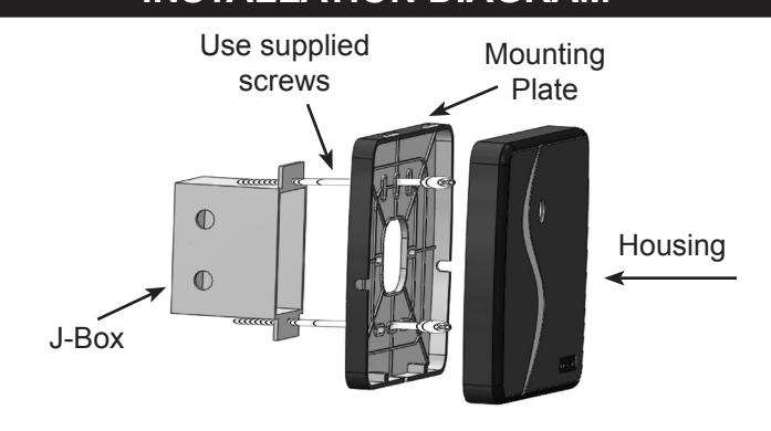
Installation Steps For Midrange Reader
- 1. This reader is designed to mount on any flat surface. For outdoor mounting, especially on masonry, silicone caulking is recommended.
- 2. Attach the mounting plate to the mounting surface using the appropriate fasteners
- 3. When mounting to a post flange or a J-box, use the 6-32 machine screws provided.
- 4. When mounting directly to metal, a 1-inch thick non-metallic spacer (customer supplied) between the reader and the mounting surface will improve read range.
- 5. If mounting directly to a wall surface, drill a ½" hole for the wiring connection. Using the mounting plate as a template, mark mounting hole locations, and use the #6 sheet metal screws and wall anchors provided.
- 6. Splice the connector pigtail to the cable that has been run to the control panel. Insert the connector into the back of the reader.
- 7. Attach the housing to the mounting plate by inserting the two tabs at the top of the mounting plate into the two slots inside the top of the housing.
- 8. Secure by installing two 4-40 screws into the holes at the bottom of the reader.
|
3.275"
8.32 cm |
5.8" (14.73 cm) | 5.95" (15.11 cm) | |
|---|---|---|---|
| Mounting Plate 6.0" (15.24 cm) | Reader Housing 0.96" (2.44 cm) | ||
| Wire Color | ET9-RO-W-MR |
|---|---|
| GREEN | Wiegand Data 0 |
| WHITE | Wiegand Data 1 |
| VIOLET | N/A |
| GRAY | N/A |
| ORANGE | Green LED |
| BROWN | Red LED |
| YELLOW | Buzzer |
| BLUE | Hold Line |
| RED | 5-14VDC + |
| BLACK | DC Ground |
INSTALLATION DIAGRAM
SPECIFICATIONS:
POWER REQUIREMENTS
5-14 VDC, Idle: 100 mA, When reading card: 200 mA
INPUTS & OUTPUTS
LED-Red Ground to Activate LED-Green Ground to Activate Buzzer Control Ground to Activate Hold Line Ground to Activate
Cable Distance 500 ft. Cable Type 5-10 conductor
(depending on options used)
ENVIRONMENT
Ambient Temperature -40° to +70°C (-40° to +158°F) Humidity 0 to 100% (non-condensing)
COMMUNICATIONS
Wiegand SIA Industry Standard Protocol
PARTS INCLUDED:
Reader Assembly with Mounting Plate Cable Assembly, 18"
" machine screws
4 - #6 x 3/4" sheet metal screws
4 - #6 plastic wall anchors
" machine screws
This Instruction Sheet

20301 Nordhoff Street • Chatsworth, CA 91311 phone 818-882-0020 • fax 818-882-7052
TOLL-FREE (800) 891-0020 E-mail: mail@securakey.com Web site: www.securakey.com
INSTRUCTION TO THE USER FCC ID: NNHETAGS9
This equipment has been tested and found to comply with the limits for a class B digital device, pursuant to part 15 of the FCC Rules. These limits are designed to provide reasonable protection against harmful interference in a residential installation. This equipment generates, uses and can radiate radio frequency energy and if not installed and used in accordance with the instructions, may cause harmful interference to radio communications. However, there is no guarantee that interference will not occur in a particular installation. If this equipment does cause harmful interference to radio or television reception, which can be determined by turning the equipment off and on, the user is encouraged to try to correct the interference by one or more or the following measures:
- Reorient or relocate the receiving antenna.
- Increase the separation between the equipment and receiver.
- Connect the equipment into an outlet of a circuit different from that to which the receiver is connected.
- Consult the dealer or an experienced radio/TV technician for help.
This equipment has been certified to comply with the limits for a class B computing device, pursuant to FCC Rules. In order to maintain compliance with FCC regulations, shielded cables must be used with this equipment. Operation with nonapproved equipment or unshielded cables is likely to result in interference to radio and TV reception. The user is cautioned that changes and modifications made to the equipment without the approval of the manufacturer could void the user's authority to operate this equipment.