Securakey ENTRACOMP® 26SA User Installation Manual
Open the original PDF document
View PDFENTRACOMP® 26SA With Remote Open Input
User/Installation Manual
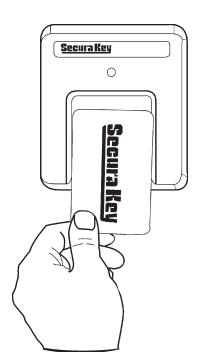

TABLE OF CONTENTS
| INTRODUCTION | 1 |
|---|---|
| SETTING THE SYSTEM (FACILITY) CODE | 3 |
| PROGRAMMING THE ENTRACOMP® 26SA | 5 |
|
VALIDATING A SINGLE CARD
|
5 |
|
VALIDATING A BLOCK OF CARDS
|
6 |
|
VOIDING CARDS
|
7 |
| SETTING THE LATCH TIMER | 7 |
| ACTIVE/INACTIVE | 7 |
| DOOR UNLOCK MODE | 8 |
| TIMED ANTIPASSBACK FEATURE | 8 |
| ANTIPASSBACK WAITING TIME | 9 |
| RELAY CONFIGURATION | 10 |
| SecurRelayTM MODE | 10 |
| INSTALLATION | 11 |
| WIRING INSTRUCTIONS | 11 |
| REMOTE OPEN | 14 |
| SECURELAYTM | 14 |
| INSTALLATION INSTRUCTIONS | 15 |
| SURFACE HOUSING TO SINGLE GANG | |
| ELECTRICAL BOX | 15 |
| SURFACE HOUSING WITHOUT | |
| ELECTRICAL BOX | 15 |
| SURFACE HOUSING WITH | |
| POST MOUNT | 16 |
| SURFACE HOUSING WITH FLANGE MOUNT | |
| ADAPTER | 17 |
| FLUSH MOUNT TO EXISTING 5S BOX | 20 |
|---|---|
| FLUSH MOUNT WITH 5S BOX | 21 |
| FLUSH MOUNT WITHOUT 5S BOX | 22 |
| METAL SURFACE HOUSING TO SINGLE GANG | |
| ELECTRICAL BOX | 25 |
| METAL SURFACE HOUSING WITHOUT | |
| ELECTRICAL BOX | 25 |
| METAL SURFACE HOUSING WITH POST | |
| ADAPTER | 26 |
| METAL SURFACE HOUSING WITH FLANGE | |
| ADAPTER | 27 |
| SPECIFICATIONS | 30 |
|
V041007 3320389-E
(6570) |
INTRODUCTION
The ENTRACOMP® 26SA is a stand alone access control system that will control access to a passageway for up to 65,503 individuals.
There are two kinds of cards used with the ENTRACOMP® 26SA , access cards and program cards.
Access cards are used by individuals to gain access to the passageway. Each access card is magnetically encoded with two types of information: the system code (or facility code) and the ID number. Your access cards will all have the same system code, but each will have its own ID number. Your unique system code is what prevents cards from other systems from activating your unit. The ID number is what distinguishes one user card from another.
NOTE: The 26SA can not recognize ID numbers higher than 65,503 .
Program cards are used to tell the ENTRACOMP® 26SA what it is to do. As with access cards, program cards are magnetically encoded with a common system code and instruction information. The system code of your program cards is the same as the system code of your access cards. Your unique system code is what prevents program cards from other systems from programming your system. There are 15 different program cards. There are ten number cards (0 through 9) and five function cards. The program cards are as follows:
| "0" | ZERO |
|---|---|
| "1" | ONE |
| "2" | TWO |
| "3" | THREE |
| "4" | FOUR |
| "5" | FIVE |
| "6" | SIX |
| "7" | SEVEN |
| "8" | EIGHT |
| "9" | NINE |
"VALID" VALIDATE
"VOID" VOID OR CANCEL "*" THRU
"SET TIMER" SET LATCH TIMER OR
ANTIPASSBACK TIMER
"ACTIVE/INACTIVE" - ACTIVATE OR INACTIVATE SYSTEM

Secura Key • 2
SETTING THE SYSTEM (FACILITY) CODE
When received, the correct system code may already be set. Should it become necessary to reset the system code, remove the unit from the wall to gain access to the reset button (see figure 1). Momentarily depress the reset button. The LED indicator will flash red and green alternately (If at power up, the LED is already flashing red/green, it is not necessary to remove the unit from the wall and press the reset button). While the LED indicator is flashing, place either a programming card or an access card with the proper system code onto the touch plate and after the LED turns solid Green, remove it. The ENTRACOMP® 26SA will "remember" the system code and retain it until reprogrammed. If the reset button is pushed, but no card is placed on the TOUCH CARD® reader plate before the LED indicator times out, the system code will be unchanged. Wait for the LED indicator to time out before programming the unit.
There may occur situations which require the unit to recognize more than one system (facility) code. The ENTRACOMP® 26SA can be set to recognize up to ten (10) different system codes. To program multiple system codes, follow the procedure above for programming a single system code, but place a card with the second system code (and third system code if necessary) on the TOUCH CARD® reader plate before the red/green LED indicator times out. When more than one facility code has been programmed, the unit will not distinguish between cards having different facility codes but the same ID number.
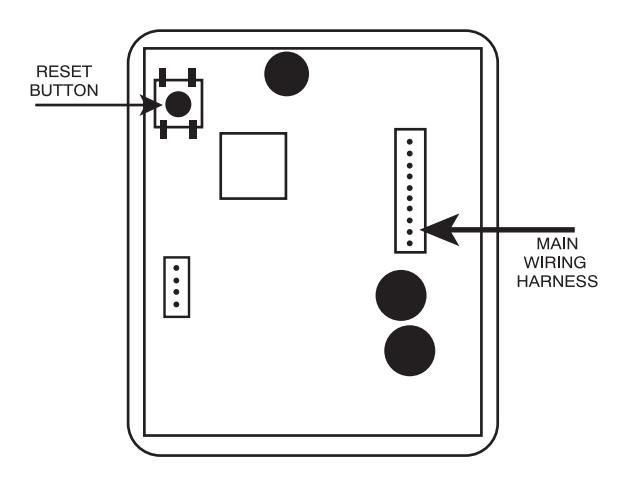
FIGURE 1
PROGRAMMING THE ENTRACOMP® 26SA
Functions of the ENTRACOMP® 26SA are programmed by placing the program cards on the TOUCH CARD® reader plate in a proper sequence. It is helpful to think of placing a program card on the TOUCH CARD® reader plate as depressing a key on a keyboard or key pad. You may begin programming at any time by placing the first program card of the sequence on the TOUCH CARD® reader plate. At this point the LED indicator will show an amber color. When you remove the program card from the TOUCH CARD® reader plate, the LED indicator will flash the amber color awaiting the next program card. Placement of the next program card on the TOUCH CARD® reader plate causes the amber LED to stop flashing and become solid. In like manner, the remainder of the program cards for the programming sequence are placed on the TOUCH CARD® reader plate. At the end of the programming sequence, the LED indicator will flash green to indicate that the programming instruction has been accepted. While programming, it is necessary to place the next card of the sequence on the TOUCH CARD® reader plate while the LED indicator is flashing amber (you have approximately 10 seconds between each card). If the amber LED times out, it will be necessary to restart the programming sequence. Should an error be made in the programming sequence, the LED indicator will flash red instead of green.
VALIDATING A SINGLE CARD . To validate a single card, place the sequence of program cards representing the card number on the TOUCH CARD® reader plate and then place the "VALID" card on the TOUCH CARD® reader plate.
Example: Validate card number 100.
Place the "1" card on the TOUCH CARD® reader plate, remove it and place the "0" card on the TOUCH CARD® reader plate, remove it and place again the "0" card on the TOUCH CARD® reader plate, remove it and place the "VALID" card on the TOUCH CARD® reader plate, and remove it.
1 + 0 + 0 + VALID
VALIDATING A BLOCK OF CARDS. To validate a block (continuous sequence) of cards, place the sequence of cards representing the first card number of the block on the TOUCH CARD® reader plate, then the "*" (THRU) card, then the sequence of cards representing the last card number of the block, and then place the "VALID" card on the TOUCH CARD® reader plate.
Example: Validate cards 5 thru 225.
NOTE: After a block Validate or Void is complete, the LED will turn Green. Then the reader will beep and the LED will turn off.
Place the "5" card on the TOUCH CARD® reader plate, remove it and place the "*" (THRU) card on the TOUCH CARD® reader plate, remove it and place the "2" card on the TOUCH CARD® reader plate, remove it and again place the "2" card on the TOUCH CARD® reader plate, remove it and place the "5" card on the TOUCH CARD® reader plate, remove it and place the "VALID" card on the TOUCH CARD® reader plate, and remove it.
5 + * + 2 + 2 + 5 + VALID
VOIDING CARDS . Cards may also be voided (cancelled) either singly or in blocks. Follow the instructions for validating above, replacing the "VALID" card with the "VOID" card.
SETTING THE LATCH TIMER . The output from the relay may be set to any number of seconds from 1 to 99. To set the latch timer, place on the TOUCH CARD® reader plate the sequence of program cards representing the number of seconds the latch is to be on, then place the "SET TIMER" card on the TOUCH CARD® reader plate and remove it.
Example: Set latch timer for 15 seconds.
Place the "1" card on the TOUCH CARD® reader plate, remove it and place the "5" card on the TOUCH CARD® reader plate, remove it and place the "SET TIMER" card on the TOUCH CARD® reader plate, and remove it.
1 + 5 + SET TIMER
Setting the latch timer to "0" produces a 0.25 second output, timed from when a valid card is placed on the TOUCH CARD® reader plate.
ACTIVE/INACTIVE . The ENTRACOMP® 26SA may be made inactive for entry by placing the "ACTIVE/INACTIVE" card on the TOUCH CARD® reader plate and then removing it. While the reader is in the inactive mode, the LED indicator will flash red approximately once every second. The unit may not be programmed and will not grant access to any cards while it is in the inactive mode. To reactivate the reader, again place the "ACTIVE/ INACTIVE" card on the TOUCH CARD® reader plate and remove it.
DOOR UNLOCK MODE. The relay may be set to stay latched (door unlocked) during periods when access control is unwanted. While in the "DOOR UNLOCK" mode, the relay stays activated, and the LED indicator will flash green approximately once every second. The unit may not be programmed with the programming deck, nor will it recognize access cards while in the "DOOR UNLOCK" mode. To set the unit to the "DOOR UNLOCK" mode, place the "*" (THRU) card on the TOUCH CARD® reader plate, remove it and place the "ACTIVE/ INACTIVE" card on the TOUCH CARD® reader plate and remove it.

To return the ENTRACOMP® 26SA to normal operation, place the "ACTIVE/ INACTIVE" card on the TOUCH CARD® reader plate and remove it.
TIMED ANTIPASSBACK FEATURE . If the Timed Antipassback feature is activated, a card used for entry is made temporarily void for a settable amount of waiting time. The purpose of this feature is to deter a user from "passing back" his card to another for unauthorized entry. Once activated, you must set an antipassback waiting time for this feature to be functional.
To activate the Timed Antipassback feature, place the "*" (THRU) card on the TOUCH CARD® reader plate and remove it. Then place the "SET TIMER" card on the TOUCH CARD® reader plate and remove it. Then place the "VALID" card on the TOUCH CARD® reader plate and remove it.

To deactivate the Timed Antipassback feature, place the "0" card on the TOUCH CARD® reader plate and remove it. Then place the "*" card on the TOUCH CARD® reader place and remove it. Then place the "SET TIMER" card on the TOUCH CARD® reader plate and remove it.

ANTIPASSBACK WAITING TIME . The antipassback waiting time may be set to any number of minutes from 1 to 99. However, the actual waiting time will fl uctuate between the time set and twice the time set. Thus, if the antipassback time is set to 5 minutes, users will have to wait a minimum of 5 minutes and a maximum of 10 minutes before reentry will be allowed. Setting the antipassback waiting time to 0 will disable the Antipassback feature and reentry will be allowed immediately. See above to re-activate the Antipassback feature.
To set the antipassback waiting time , place on the TOUCH CARD® reader plate the sequence of cards representing the number of minutes of the minimum waiting period (1 to 99), then place the "*" card on the TOUCH CARD® reader place and remove it, then place the "SET TIMER" card on the TOUCH CARD® reader plate and remove it.
Example: Set antipassback waiting time to 3 minutes.
Place the "3" card on the TOUCH CARD® reader plate, remove it, and place the "*" on the TOUCH CARD® reader plate, remove it, and place the "SET TIMER" card on the TOUCH CARD® reader plate, and remove it.
3 + * Secura Key • 9
+ SET TIMER
RELAY CONFIGURATION. The solid-state relay can be set to be Normally Closed, Normally Open or to operate with the SecuRelay<sup>™</sup> for increased vandal resistance.
Selections are:
- 6. Normally Open (Factory default)
- 7. Normally Closed
- SecuRelay<sup>™</sup> Option.
The default mode is Normally Open (NO). To place the relay in the Normally Open (NO) mode, place the "**" card on the reader twice, followed by the "6" card.
To place the relay in the Normally Closed (NC) mode, place the "*card on the reader twice, followed by the "7" card.
To place the unit in the SecuRelay™ mode, place the "*" card on the reader twice, followed by the "8" card.
To return to normal mode, place the "*" card on the reader twice followed by the "1" card.
INSTALLATION
WIRING INSTRUCTIONS
The ENTRACOMP® 26SA is provided with a connector and 7 wire leads (See Figure 1). Using appropriate wire nuts or crimp on connectors, wire the unit as per the table below. Be sure unused wires are insulated to avoid shorting. In addition to the wiring below, AN EARTH GROUND IS REQUIRED . It must be connected to the green screw on the mounting bracket .
| WIRE | COLOR | DESCRIPTION |
|---|---|---|
| 1 | WHITE | 10-24 VAC OR |
| 2 | WHITE | 10-24 VDC |
| 3 | YELLOW | NORMALLY OPEN * |
| 4 | N/A | NOT USED |
| 5 | GREEN | COMMON |
| 6 | N/A | NOT USED |
| 7 | RED | 8 VDC FOR SECURELAY™ |
| 8 | N/A | NOT USED |
| 9 | ORANGE | REMOTE OPEN |
| 10 | BROWN | REMOTE OPEN |
| * Can be reprogrammed as Normally Closed, See page 10. | ||
TABLE 1
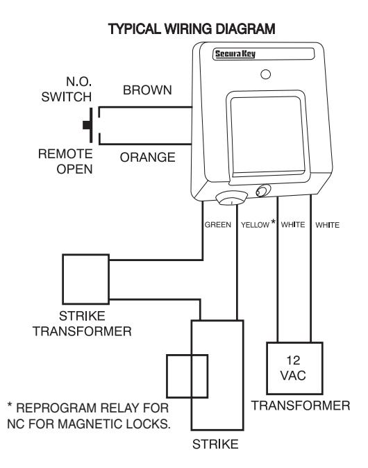
FIGURE 2.
Secura Key • 12
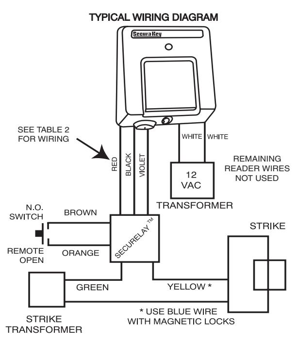
FIGURE 3
Secura Key • 13
REMOTE OPEN (REX). Connect the Brown and orange wires to any Normally Open switch. Closing this circuit will activate the Latch Relay for the number of seconds you have selected when you set the Latch Timer.
SecuRelayTM . The SecuRelayTM from Secura Key may be purchased separately for use with ENTRACOMP® 26SA units which have firmware version 4.0 or later. SecuRelayTM allows the lock/gate control circuit to be remotely located so that attacking the 26SA will not open the passageway on the SecuRelayTM wiring harness. The 3 pin connector must be cut off and the following connections must be made.
| SecuRelay™ | ENTRACOMP® 26SA |
|---|---|
| RED WIRE | RED WIRE (PIN 7) |
| VIOLET WIRE | YELLOW WIRE (PIN 3) |
| BLACK WIRE | BROWN WIRE (PIN 10) |
| N/A |
CONNECT GREEN WIRE (PIN 5)
TO BROWN WIRE (PIN 10) |
TABLE 2
NOTE: Remote Open must be disabled if SecuRelayTM is used.
INSTALLATION INSTRUCTIONS
SURFACE HOUSING TO SINGLE GANG ELECTRICAL BOX (See Figure 4)
- 1. For exterior walls, apply 1/4 inch bead of silicone sealant around rear perimeter surface of mounting bracket gasket. Be sure there is sufficient sealant to make a good seal between gasket and wall.
- 2. Use two 6-32 x 1 pan head screws provided to secure mounting plate to box.
- 3. Connect power and control lines to wire leads provided as per the wiring instructions.
- 4. Plug connector into reader board.
- 5. Place ENTRACOMP® 26SA housing against mounting plate, top edge first, centering housing on retaining tabs. Secure housing to plate at bottom using one 6-32 x 3/8 security screw provided or equivalent.
- 6. Lock cam lock.
SURFACE HOUSING WITHOUT ELECTRICAL BOX (See Figure 5)
1. For exterior walls, apply 1/4 inch bead of silicone sealant around rear perimeter surface of mounting bracket gasket. Be sure there is sufficient sealant to make a good seal between gasket and wall.
- 2. Mount plate to wall using appropriate fasteners. Use at least four of six holes provided.
- 3. Connect power and control lines to wire leads provided as per the wiring instructions.
- 4. Plug connector into reader board.
- 5. Place ENTRACOMP® 26SA housing against mounting plate, top edge first, centering housing on retaining tabs. Secure housing to plate at bottom using one 6-32 x 3/8 security screw provided or equivalent.
- 6. Lock cam lock.
SURFACE HOUSING WITH POST MOUNT ADAPTER (See Figure 6)
- 1. Mount post mount adapter (optional) to post (not supplied). Screw 1 1/2 inch pipe coupling on rear of post mount adapter plate to post until almost tight, stopping when reader cover is at top (12 O'clock). A small tack weld is strongly suggested to keep the housing from rotating on post.
- 2. Apply 1/8 inch bead of silicone sealant around rear perimeter surface of mounting bracket gasket.
- 3. Press plate against adapter and secure with four 10-32 x 5/16 pan head screws (provided).
- 4. Connect power and control lines to wire leads provided as per the wiring instructions.
- 5. Plug connector into reader board.
- 6. Place ENTRACOMP® 26SA housing against mounting plate, top edge first, centering housing on retaining tabs. Secure housing to plate at bottom using one 6-32 x 3/8 security screw provided or equivalent.
- 7. Lock cam lock.
SURFACE HOUSING WITH FLANGE MOUNT ADAPTER (See Figure 7)
- 1. Position flange mount adapter (optional) against post flange (not supplied). Locate and mark four (untapped) holes. Then drill and tap four 10-32 holes in post flange.
- 2. Apply silicone bead around perimeter of post flange. Place flange mount adapter against post flange and secure with four 10-32 x 1/2 flat head countersunk screws provided.
- 3. Follow instructions 2 7 for post mount adapter.
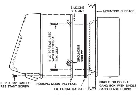
FIGURE 4
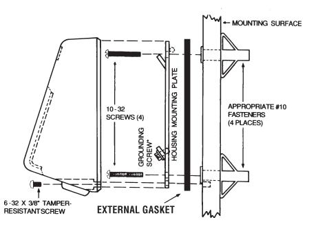
FIGURE 5
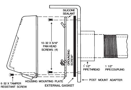
FIGURE 6
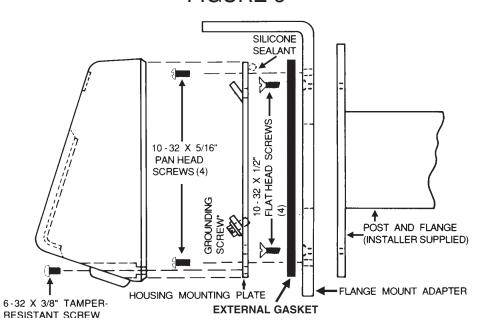
FIGURE 7
FLUSH MOUNT TO EXISTING 5S BOX (See Figure 8)
- 1. Use wall cutout template provided. Align template over 5S box. (When running wires to the 5S box, don't use center top hole as it will interfere with housing lock.) Transfer appropriate cutout corner locations of clearance hole for the housing lock to the wall with pointed instrument.
- 2. Draw lines from point to point, outlining cutout.
- 3. Cut out opening, being careful not to make opening larger than indicated on the template.
- 4. Mount mounting plate to 5S box using the four 8-32 flat head screws provided. For an outdoor installation, silicone sealant is recommended between the mounting plate and the wall.
- 5. Be sure all appropriate wiring has been connected to the terminal board, and then plug the terminal board cable into the socket on the circuit board (see wiring instructions).
- 6. Place reader and faceplate assembly against the mounting plate. Faceplate will hook onto mounting plate by pushing plate in and then sliding it down.
- 7. Secure faceplate to mounting plate using the two 4-40 screws provided.
- 8. Place faceplate door into door opening and rotate key 90° clockwise.
FLUSH MOUNT WITH 5S BOX (See Figure 9)
- 1. Use the wall cutout template provided. Locate template on the wall. Transfer appropriate cutout corner locations to the wall with a pointed instrument.
- 2. Draw lines from point to point, outlining cutout.
- 3. Cut out opening, being careful not to make opening larger than indicated on the template.
- 4. Place mounting plate against wall in its proper location. Using it as a template, mark four holes in corners. Remove faceplate, and using appropriate drill, drill four holes for appropriate fasteners (8-32 fasteners are recommended).
- 5. Fasten mounting plate to 5S box using the four 8-32 flat head screws provided. (When running wires to the 5S box, don't use the center top hole as it will interfere with the housing lock.)
- 6. Secure mounting plate and 5S box to wall. Screws must be flat head countersunk #6 or #8. Make sure any cables have been pulled into the box prior to securing assembly to wall. For an outdoor installation, silicone sealant is recommended between the mounting plate and the wall.
- 7. Be sure all appropriate wiring has been connected to the terminal board and then plug the terminal board cable into the socket on the circuit board (see wiring instructions).
- 8. Place reader and faceplate assembly against the mounting plate. Faceplate will hook onto mounting plate by pushing plate in and then sliding it down.
- 9. Secure faceplate to mounting plate using the two 4-40 screws.
- 10. Place faceplate door into door opening and rotate key 90° clockwise.
FLUSH MOUNT WITHOUT 5S BOX (See Figure 10)
- 1. Use the wall cutout template provided. Locate template on the wall. Transfer appropriate cutout corner locations to the wall with a pointed instrument.
- 2. Draw lines from point to point, outlining cutout.
- 3. Cut out opening, being careful not to make opening larger than indicated on the template.
- 4. Place mounting plate against wall in its proper location. Using it as a template, mark four holes in corners. Remove faceplate and using appropriate drill, drill four holes for appropriate fasteners (8-32 fasteners are recommended).
- 5. Secure mounting plate to wall. Screws must be flat head countersunk #6 or #8. For an outdoor installation, silicone sealant is recommended between the mounting plate and the wall.
- 6. Be sure all appropriate wiring has been connected to the terminal board and then plug the terminal board cable into the socket on the circuit board (see wiring instructions).
- 7. Place reader and faceplate assembly against the mounting plate. Faceplate will hook onto mounting plate by pushing plate in and then sliding it down.
- 8. Secure faceplate to mounting plate using the two 4-40 screws.
- 9. Place faceplate door into door opening and rotate key 90° clockwise.
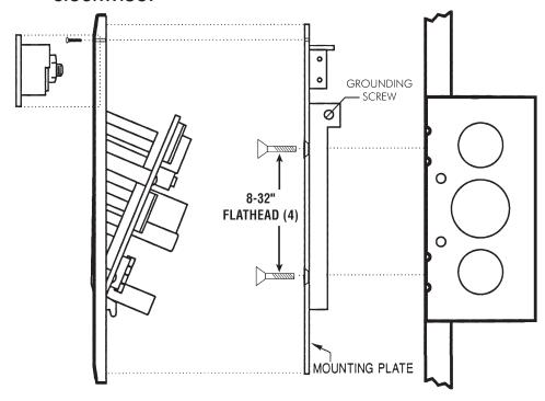
FIGURE 8
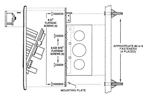
FIGURE 9
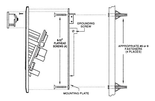
FIGURE 10
METAL SURFACE HOUSING TO SINGLE GANG ELECTRICAL BOX (Figure 11)
- 1. For exterior walls, apply 1/4 inch bead of silicone sealant around rear perimeter surface of mounting bracket gasket. Be sure there is sufficient sealant to make a good seal between gasket and wall.
- 2. Use two 6-32 x 1 pan head screws provided to secure mounting bracket and gasket to box.
- 3. Connect power and control lines to wire leads provided as per the wiring instructions.
- 4. Plug connector into reader board.
- 5. Place ENTRACOMP® 26SA housing over mounting bracket. Push housing in against wall. Secure housing to mounting bracket in door opening using two 6-32 x 3/8 screws provided. Secure housing to bracket at bottom using one 6-32 x 1/4 security screw provided or equivalent.
- 6. Place housing door into door opening and rotate key 90 degrees clockwise.
METAL SURFACE HOUSING WITHOUT ELECTRICAL BOX (See Figure 12)
1. For exterior wall, apply sealant to rear perimeter of mounting bracket gasket.
- 2. Mount plate to wall using appropriate fasteners. Use at least four of six holes provided.
- 3. Connect power and control lines to wire leads provided as per the wiring instructions.
- 4. Plug connector into reader board.
- 5. Place ENTRACOMP® 26SA housing over mounting bracket. Push housing in against wall. Secure housing to mounting bracket in door opening using two 6-32 x 3/8 screws provided. Secure housing to bracket at bottom using one 6-32 x 1/4 security screw provided or equivalent.
- 6. Place housing door into door opening and rotate key 90° clockwise.
METAL SURFACE HOUSING WITH POST ADAPTER (See Figure 13)
- 1. Mount post mount adapter (optional) to post (not supplied). Screw 1 1/2 inch pipe coupling on rear of post mount adapter plate to post until almost tight, stopping when reader cover is at top (12 O'clock). A small tack weld is strongly suggested to keep the housing from rotating on post.
- 2. Apply 1/8 inch bead of silicone sealant around rear perimeter surface of mounting bracket gasket.
- 3. Press bracket with gasket against adapter and secure with the four 10-32 x 5/16 pan head screws provided.
- 4. Connect power and control lines to wire leads provided as per the wiring instructions.
- 5. Plug connector into reader board.
- 6. Place ENTRACOMP® 26SA housing over mounting bracket. Push housing in against wall. Secure housing to mounting bracket in door opening using two 6-32 x 3/8 screws provided. Secure housing to bracket at bottom using one 6-32 x 1/4 security screw provided or equivalent.
- 7. Place housing door into door opening and rotate key 90 degrees clockwise.
METAL SURFACE HOUSING WITH FLANGE ADAPTER (See Figure 14)
- 1. Position flange mount adapter (optional) against post flange (not supplied). Locate and mark four (untapped) holes. Then drill and tap four 10-32 holes in post flange.
- 2. Apply silicone bead around perimeter of post flange. Place flange mount adapter against post flange and secure with four 10-32 x 1/2 flat head countersunk screws provided.
- 3. Follow instructions 2 7 for post mount adapter.
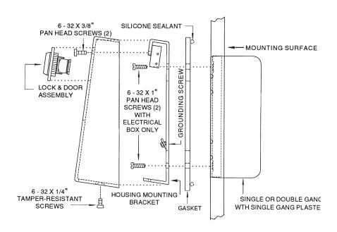
FIGURE 11
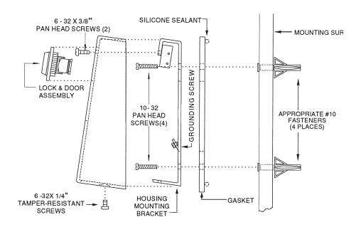
FIGURE 12
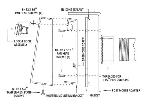
FIGURE 13
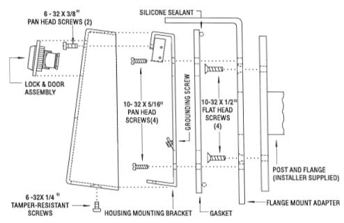
FIGURE 14
Secura Key • 29
SPECIFICATIONS
PHYSICAL
| Surface Housing | Flush Housing | Metal Housing | |
|---|---|---|---|
| Depth | 2.25 in (5.72 cm) | 1.50 in (3.8 cm) | 1.75 in (4.45 cm) |
| Width | 4.00 in (10.16 cm) | 5.50 in (13.97 cm) | 4.00 in (10.20 cm) |
| Height | 4.60 in (11.70 cm) | 7.63 in (19.38 cm) | 5.62 in (14.30 cm) |
| Weight |
20 oz
(0.57 kg) |
18 oz (0.51 kg) | 45 oz (1.28 kg) |
| Material | Lexan7 | (Polycarbonate) meets UL standard | All Steel |
POWER REQUIREMENTS
94 flame retardant rating
10 to 24 VAC, 70 mA , 50 or 60 Hz or 10 to 24 VDC, 70 mA
OUTPUTS
| Latch | SPST contact, 1A up to 60 VAC or DC |
|---|---|
| Tamper (optional) | SPDT contact, 115 VAC, 2A maximum |
INPUTS
Remote Open (REX) Close circuit to operate Latch Relay
ENVIRONMENT
Ambient Temperature -40 o F to 158 o F (-40 o C to 70 o C)
Humidity 0% to 95% relative humidity (non-condensing)
OPERATIONAL
Memory E 2 PROM (non-volatile)
Card Capacity 65,503 cards
Facility Code Up to 10 different codes simultaneously Latch Relay Programmable from 1 to 99 seconds Timed Antipassback Programmable from 1 to 99 minutes
This product complies with UL 294 standards.
WARRANTY (U.S. and Canadian)
"Secura Key products are warranted against defects in materials and workmanship for a period of 2 years from the date of purchase. Secura Key will replace any Secura Key manufactured product, except cards or tags, returned to us freight prepaid within the warranty period. This warranty does not include freight, taxes, duties, or installation expenses. THE WARRANTY SET FORTH ABOVE IS EXCLUSIVE AND NO OTHER WARRANTY, WHETHER WRITTEN OR ORAL, IS EXPRESSED OR IMPLIED. SECURA KEY SPECIFICALLY DISCLAIMS ANY IMPLIED WARRANTIES OR MERCHANTABILITY AND FITNESS FOR A PARTICULAR PURPOSE. The remedies provided herein are the buyers' sole and exclusive remedies. In no event shall Secura Key be liable for direct, indirect, special, incidental or consequential damages (including loss of profits), whether based on contract, tort or any other legal theory." Contact Secura Key for Export Warranty Policy.
Warning :
This equipment generates, uses, and can radiate radio frequency energy and if not installed and used in accordance with the instruction manual, may cause interference to radio communica tions. It has been tested and found to comply with the limits for a Class A computing device pursuant to Subpart J of Part 15 of FCC Rules, which are designed to provide reasonable protection against such interference when operated in a commercial environ ment. Operation of this equipment in a residential area is likely to cause interference in which case the user at his own expense will be required to take whatever measures may be re quired to correct the interference.

20301 Nordhoff Street Chatsworth, CA 91311 Phone: 818-882-0020 • Fax: 818-882-7052
TOLL FREE (800) 891-0020 www.securakey.com mail@securakey.com