Schlage_ALX_Vandlgard_Conversion_Instruction_Sheet_113357 – English
Open the original PDF document
View PDFALX Series Vandlgard Conversion

For ALX functions: ALX40, ALX44, ALX50, ALX53, ALX70, ALX80
These instructions describe conversion of ALX locks to or from Vandlgard functionality.
Tools and materials needed:
- small drop cloth or rag
- disposable gloves
- phillips head screwdriver
- lever removal tool
- lock grease
CAUTION
Wear protective eyewear to avoid potential injury.
BEFORE YOU BEGIN, CHECK THAT LOCK IS UNLOCKED
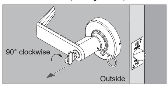
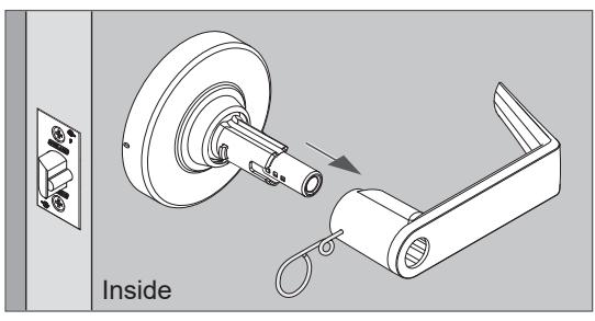
1 Remove the cylinder, outside lever, and outside rose.
Lever with KIL cylinder
- 1. Insert key and turn 90 degrees clockwise.
- 2. Push the lever catch with the pin wrench.
- 3. Pull off the lever while pushing on the pin wrench.
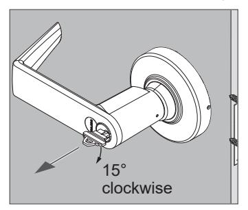
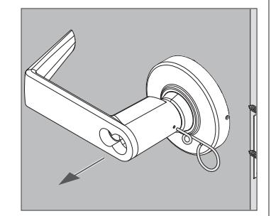
Lever with IC cylinder
- 1. Insert control key and turn 15 degrees clockwise.
- 2. Pull out the cylinder.
- 3. Push the lever catch with the pin wrench.
- 4. Pull off the lever while pushing on the pin wrench.
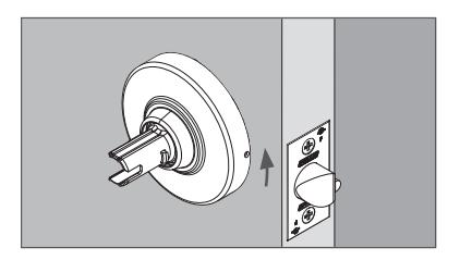
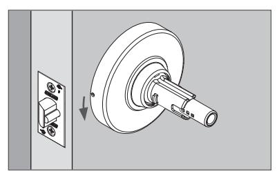
Rose
- 1. Rotate the rose counterclockwise approximately 10°.
- 2. Remove the rose.
2 Remove the inside lever and inside rose.
- 2a Push the lever catch with the pin wrench.
- 2b Pull off the lever while pushing on the pin wrench.
ALX50 shown
2c Rotate the rose counterclockwise approximately 10°. Then, remove the rose.
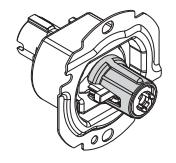
3 Remove inside spring cage assembly.
ALX50 shown
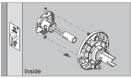
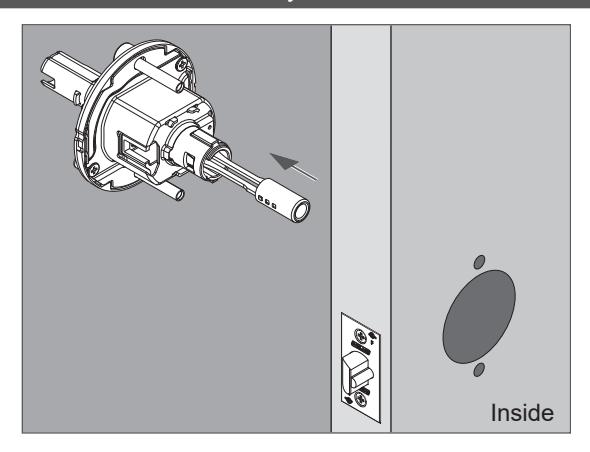
4 Remove chassis assembly from the door.
5 Remove two screws from the back of chassis assembly.
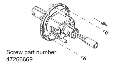
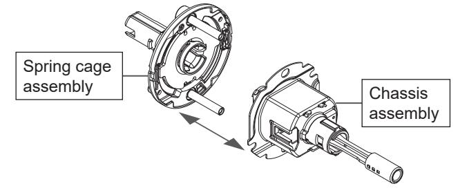
6 Separate chassis assembly from outside spring cage assembly.
CAUTION - Separate the assemblies carefully as springs may pop out.
Protect hands and work surfaces from grease.
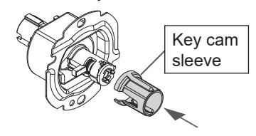
7 Move key cam sleeve from the spring cage to chassis assembly.
7a Take the key cam sleeve out of the spring cage assembly.
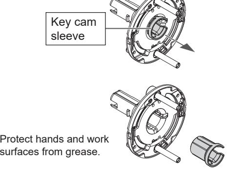
7b Place the key cam sleeve on the chassis assembly as shown.
8 Hold the outside spring cage assembly with spindle facing down and push the spindle up to disassemble.
CAUTION - Springs will pop out of the assembly. Keep fingers around the parts as they come out.
Protect hands and work surfaces from grease.
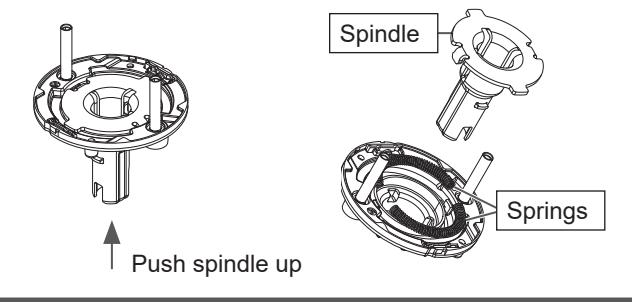
- 9 Rotate the spring cage housing and reinstall springs.
- 9a Set the spings aside.
- Take care to keep debris off the springs after removal.
- Avoid wiping grease away from the springs or from inside the spring cage housing.
- 9b Rotate the spring cage housing 180 degrees.
- Note the starting position of the "V" and rotate so that the "V" is on the opposite side.
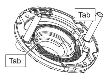
9c Reinstall the springs. The springs fit against the tabs as shown. CAUTION - Use both hands to reinstall each spring as tension may cause a spring to pop out again.
10 Determine correct position and reinstall the spindle.
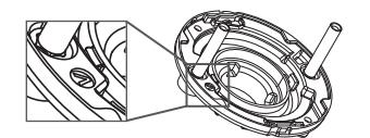
10a Check proper positioning for Vandlgard or non-Vandlgard:
- For Vandlgard (clutching) the center slot on the spindle must face the center of the wide curved indent in the spring cage (see detail below).
- For non-Vandlgard (non-clutching/rigid lever) the center slot faces the opposite direction, facing the center of the narrow indent in the spring cage.
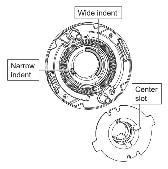
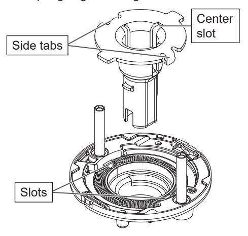
10b Snap the spindle into place with the side tabs aligned with the slots on the spring cage housing.
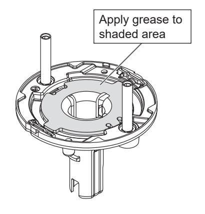
10c Apply a thin layer of lock grease to the flange on the spindle.
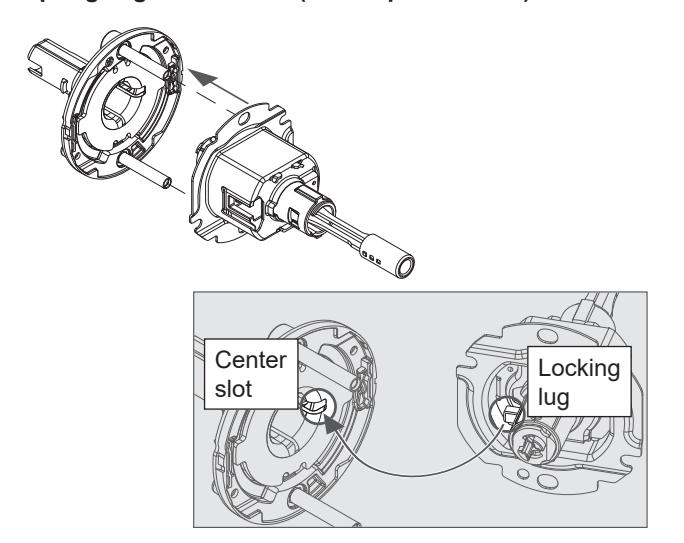
11 Reassemble the chassis assembly and outside spring cage assembly.
11a Reassemble as shown.
Be sure to align the locking lug on the chassis assembly with the center slot on the spring cage assembly.
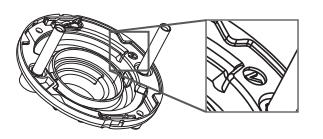
IMPORTANT! Before installing screws, confirm correct spring cage orientation (see step 11b below).
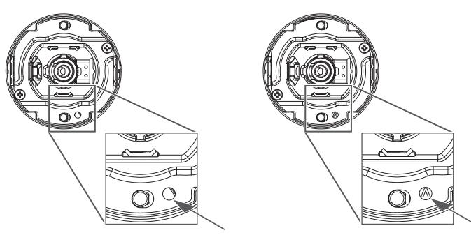
11b To check for correct orientation, look for the "V" in the opening next to the mounting post.
Non-Vandlgard, rigid lever Vandlgard lever

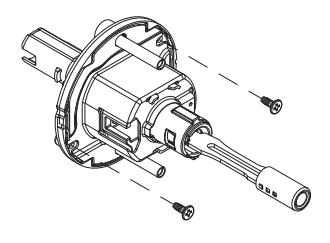
11c Reinstall two screws on spring cage assembly.
Do not use a drill driver. Do not overtighten.
Customer Service
1-877-671-7011 us.allegion.com
© Allegion 2019 Rev. 10/19