Schlage_ALX_Installation_Instructions_113125
Open the original PDF document
View PDFALX-Series

Installation Instructions
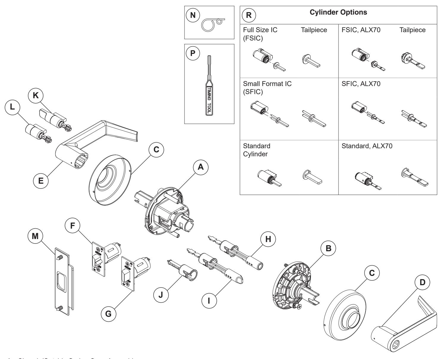
- A Chassis/Outside Spring Cage Assembly
- B Inside Spring Cage Assembly
- C Rose
- D Inside Lever
- E Outside Lever
- F Dead Latch Assembly (ALX50, ALX53, ALX70, ALX80)
- G Spring Latch Assembly (ALX10, ALX40, ALX44)
- H Push Button Plunger Assembly (ALX40, ALX44, ALX50)
- I Push-Turn Button Plunger Assembly (ALX53)
- J Storeroom Function Plunger (ALX80)
- K Outside Button Hospital/Privacy Function (ALX44)
- L Outside Button Bedroom/Bathroom Function (ALX40)
- M Strike Assembly
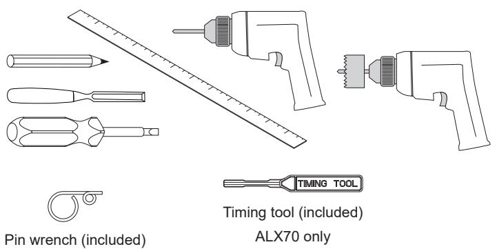
- N Pin Wrench, included
- P Timing Tool, included (ALX70 only)
- R Cylinder (ALX50, ALX53, ALX70, ALX80)
| INDEX | |
|---|---|
| TOOLS | 2 |
| INSTALLATION PREPARATION | 2 |
| BASIC LOCK INSTALLATION | 2 |
| KIT LOCK ASSEMBLY | 5 |
| ALX70 | 8 |
| LOCK DISASSEMBLY | 12 |
| LOCK FUNCTIONAL TESTING | 13 |
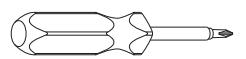
TOOLS
INSTALLATION PREPARATION
Tools required:
Optional tools:
Door preparation:
Before installation, check the door for proper preparation.
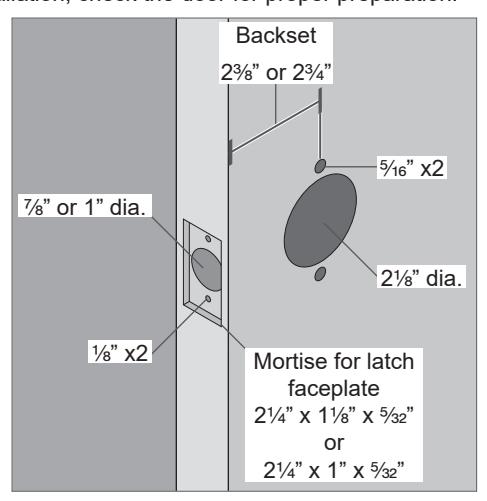
To prepare a door, use the template included in the package with the lock. For additional information, visit the website www.allegion.com/us or contact technical support at 877-671-7011 (U.S.) or 800-900-4734 (Canada) .
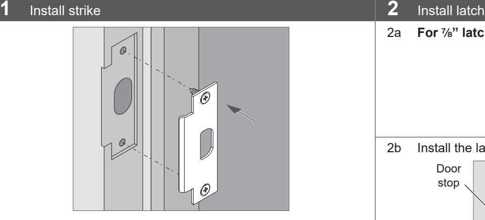
BASIC LOCK INSTALLATION
L THE FOLLOWING STEPS ARE FOR LOCKS PRECONFIGURED AT THE FACTORY.
For KIT lock products, see "KIT LOCK ASSEMBLY" on page 5.
stop
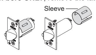
2a For M\," latch bore ONLY , remove the latch sleeve.
2b Install the latch with bevel facing toward the door stop.
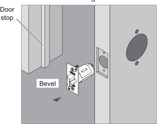
Note: For installation on unreinforced hollow metal doors, use of door spacer (part number 24483760) is recommended.
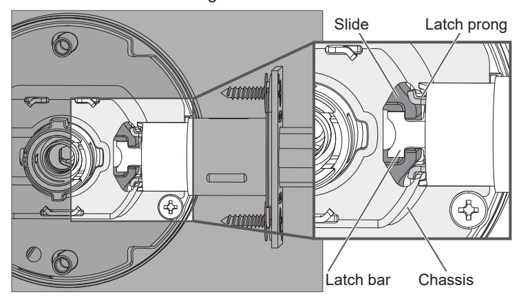
3 Install chassis/outside spring cage assembly
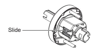
Slide faces toward door edge.
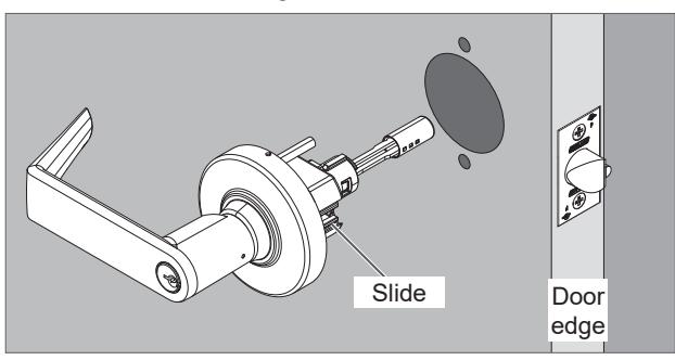
ALX50 shown
IMPORTANT! Latch prongs fit above and below the slide and inside the chassis housing.
4 Install inside spring cage assembly
Fully tighten mounting screws. Lever catch faces door edge.
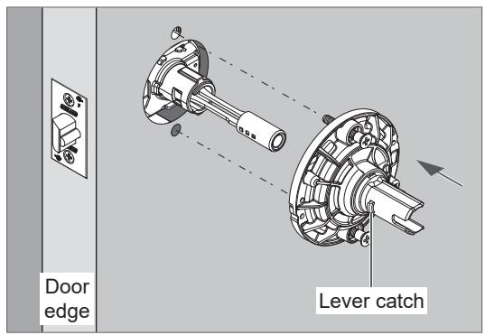
ALX50 shown
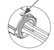
5 Install inside rose
5a Align the indent on the rose with the upper notch on the spring cage.
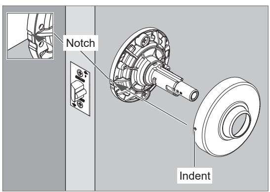
ALX50 shown
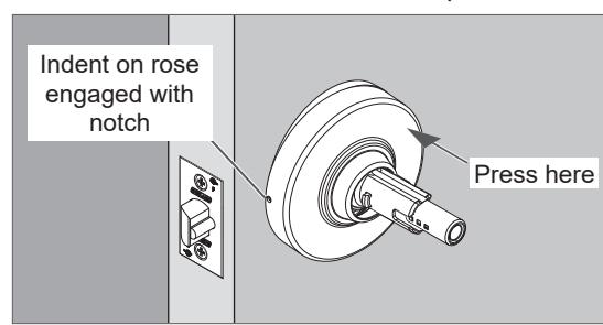
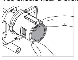
5b Place the indent on the notch with the opposite side of the rose angled slightly away from the spring cage as shown. Then, press the other side of the rose into place.
You should hear a click as the rose is pressed into place.
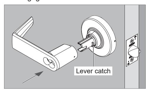
6 Install inside lever
Push the inside lever onto the spindle. Be sure to engage the lever catch.
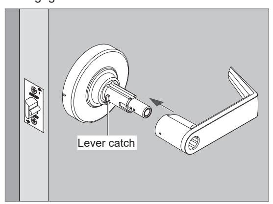
ALX50 shown
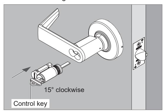
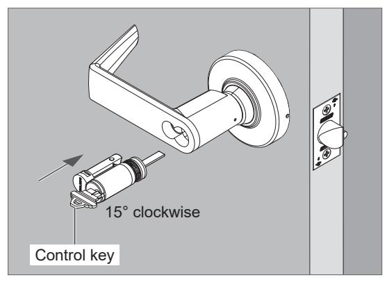
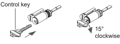
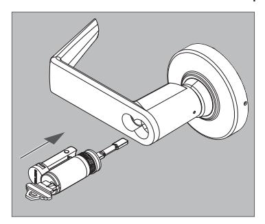
7 If applicable, install outside IC (interchangeable core) cylinder – ALX50, ALX53, ALX80 ONLY*
- * For ALX70 IC cylinder installation, see page 9 .
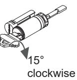
- 7a Insert the control key into the cylinder and rotate 15 degrees clockwise. Then insert the cylinder assembly into the lever.
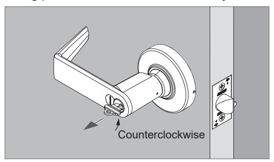
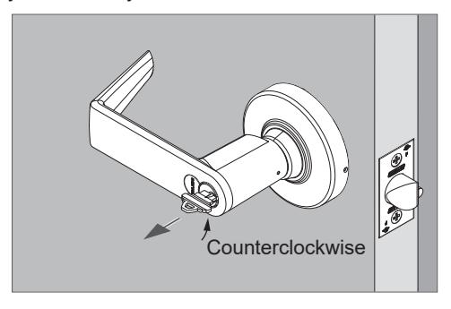
7b Rotate the key counterclockwise to starting position and remove it from the cylinder.
KIT LOCK ASSEMBLY
L The following pages describe the assembly of complete locks from product kits. Assembly for models ALX40, ALX44, ALX50, ALX53, ALX70 and ALX80 are shown.
Once assembled, refer to "BASIC LOCK INSTALLATION" on page 2 for installation on the door.
Install inside button assembly – ALX40, ALX44, ALX50 and ALX53 ONLY
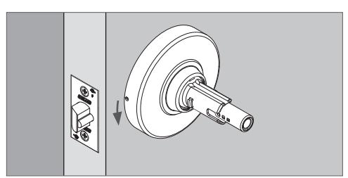
Install inside storeroom plunger – ALX80 ONLY
If necessary, adjust the positon of the button according to door thickness.
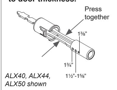
- The default position is 1C\v".
- To adjust, press and hold the shafts of the plunger assembly together (toward center).
- Move the button to the appropriate hole for door thickness.
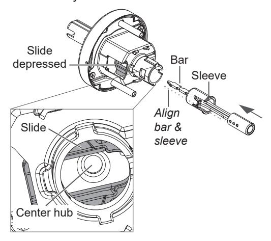
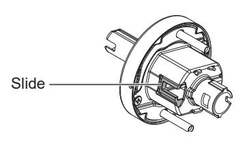
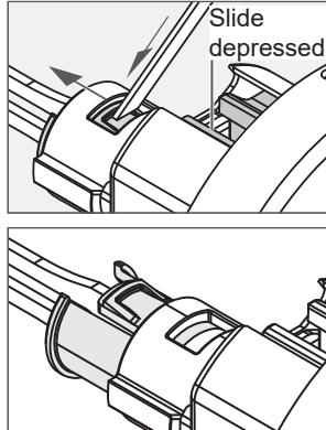
1. Push in and hold down the slide on the chassis.
2. Align the plunger bar and sleeve.
Insert the button assembly while holding the slide in as shown.
Be sure to engage the tip of the bar in the center hub of the chassis assembly.
3. Press the plunger shoulder to fit tight against the spindle.
You should hear a click.
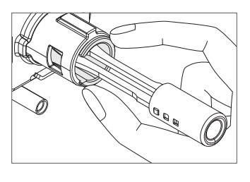
Check that the plunger assembly is correctly seated.
1. Push in and hold down the slide on the chassis.
2. While holding down the slide, insert the plunger.
Be sure to engage the tip of the plunger in the center hub of the chassis assembly.
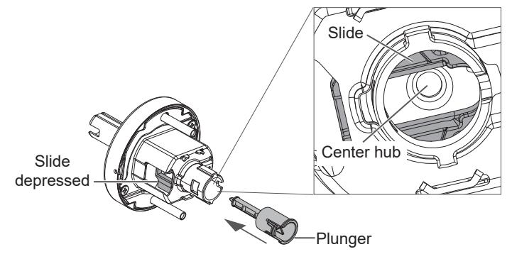
3. Press the plunger shoulder to fit tight against the spindle.
You should hear a click.
Check that the plunger is correctly seated.
See following page for assembly of outside of lock components.
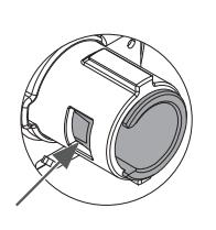
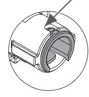
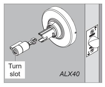
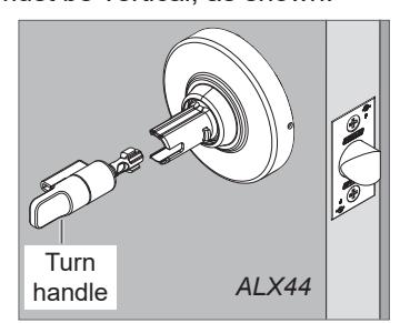
Install emergency turn with outside lever – ALX40, ALX44 ONLY
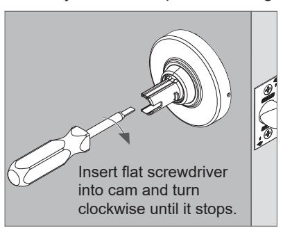
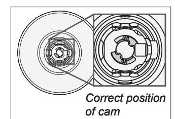
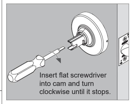
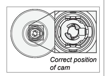
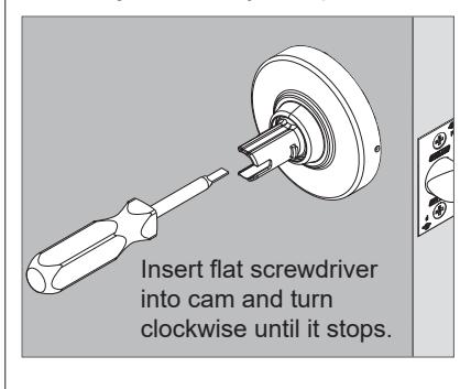
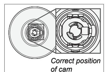
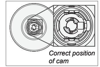
1. Adjust the cam position using a flat screwdriver.
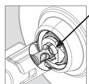
Place the turn assembly into the spindle.The turn slot or turn handle must be vertical, as shown.
Turn properly
installed
in lock hub
Push the outside lever onto the spindle.Be sure to engage the lever catch.
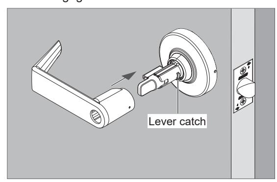
ALX44 shown
Install KIL (key-in-lever) cylinder with outside lever – ALX50, ALX53 & ALX80 ONLY For ALX70, see page 8.
See next page for IC (interchangeable core) cylinder installation.
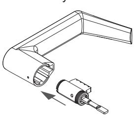
1. Adjust the cam position using a flat screwdriver.
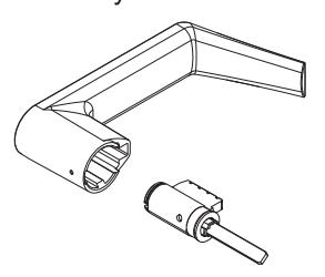
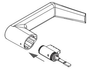
2. Place the cylinder assembly into the lever.
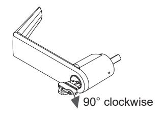
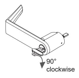
3. Insert the key and rotate 90 degrees clockwise.
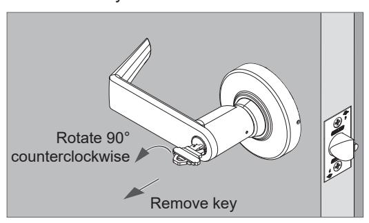
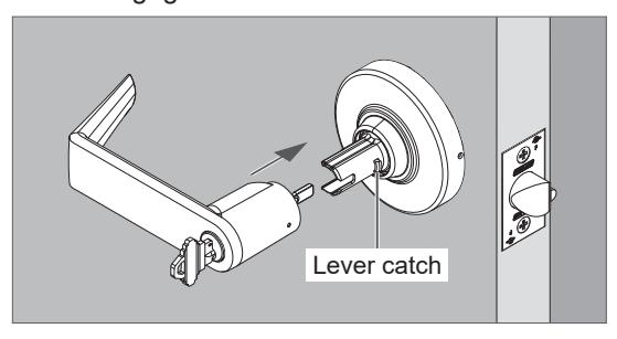
4. With key still rotated 90 degrees clockwise, push outside lever onto the spindle.
Be sure to engage the lever catch.
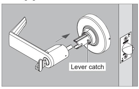
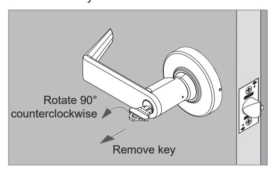
5. Rotate the key counterclockwise back to the starting position and remove the key.
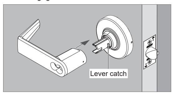
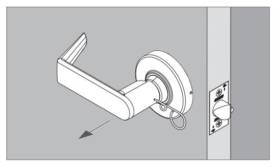
Install IC cylinder with outside lever – ALX50, ALX53 & ALX80 ONLY For ALX70 IC cylinder, see page 9
1. If the outside lever is not installed, push the lever onto the spindle.
Be sure to engage the lever catch.
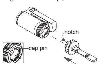
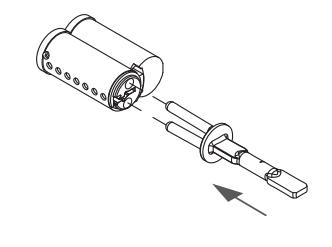
2. Install IC cylinder tailpiece.
Push tailpiece until it snaps into place.
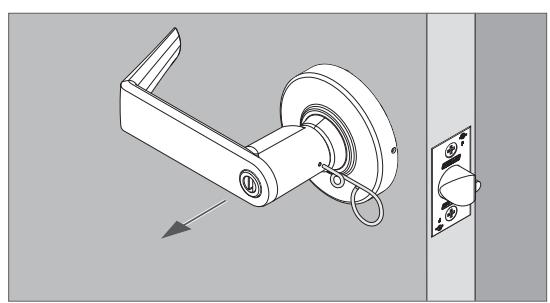
FSIC cylinder:
SFIC cylinder:
Align notch with cap pin.
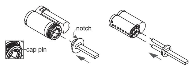
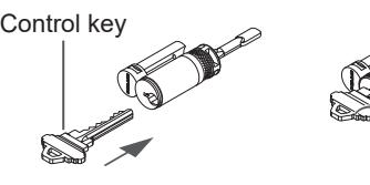
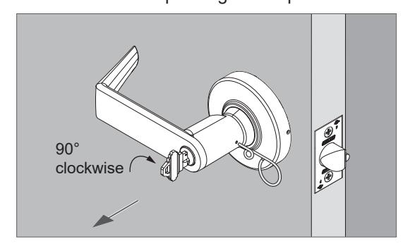
3. Insert the control key into the cylinder and rotate 15 degrees clockwise.
Then, insert the cylinder assembly into the lever.
4. Rotate the key counterclockwise until it stops and remove the key from the cylinder.
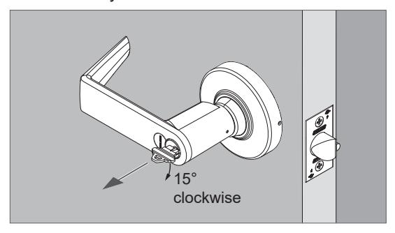
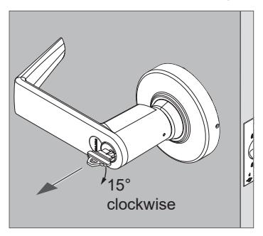
To remove IC cylinder:
Insert the control key and turn it 15 degrees clockwise, then remove cylinder.
Δ1 X70
- (i) IMPORTANT! The following steps apply ONLY to ALX70 locks. ALX70 locks include a unique cylinder tailpiece. The following steps must be used for correct cylinder installation and lock performance.
- (i) ALX70 locks require timing before cylinder installation. The Timing Tool should be used to time the lock (included with ALX70 configured locks and function kits). If the timing tool is not available, see page 10.
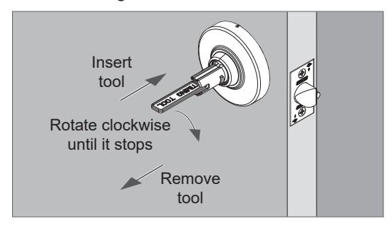
Install outside lever with KIL (key-in-lever) cylinder, ALX70 function ONLY
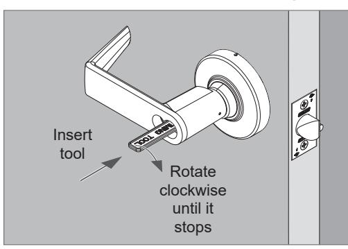
Insert the timing tool (horizontal position) into the lever spindle until the tool bottoms out.
If the timing tool is not available, see page 10.
- 2. Rotate the timing tool <u>clockwise</u> until it stops. The tool handle should be horizontal when it stops.
- 3. Remove the timing tool.
4. Adjust the keycam position using a flat screwdriver.
Place the cylinder assembly into the lever.
6. Insert the key and rotate 90 degrees <u>clockwise</u>.
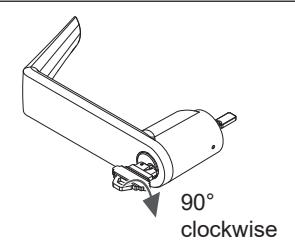
7. With key still rotated 90 degrees clockwise, push the outside lever onto the spindle.
Be sure to engage the lever catch.
8. Rotate the key counterclockwise back to the starting position and remove the key.
- L IMPORTANT! The following steps apply ONLY to ALX70 locks. ALX70 locks include a unique cylinder tailpiece. The following steps must be used for correct cylinder installation and lock performance.
- L ALX70 locks require timing before cylinder installation. The Timing Tool should be used to time the lock (included with ALX70 configured locks and function kits). If the timing tool is not available, see page 11.
Install IC cylinder into outside lever, ALX70 function ONLY
1. Insert the timing tool (horizontal position) into the lever until the tool bottoms out .
If the timing tool is not available, see page 11.
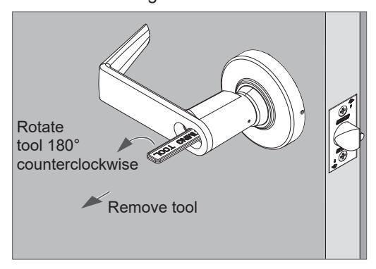
2. Rotate the timing tool clockwise until it stops . The tool handle should be horizontal when it stops .
3. Rotate the timing tool 180 degrees counterclockwise . Then remove the timing tool.
4. Install cylinder tailpiece.
Push tailpiece until it snaps into place.
FSIC cylinder:
Align notch with cap pin.
SFIC cylinder:
5. Insert the CONTROL KEY into the cylinder and turn 15 degrees clockwise.
6. Place the cylinder into the outside lever.
Then turn the key counterclockwise until it stops and remove the key.
- (1) IMPORTANT! The following steps apply ONLY to ALX70 locks. ALX70 locks include a unique cylinder tailpiece. The following steps must be used for correct cylinder installation and lock performance.
- (i) ALX70 locks require timing before cylinder installation. Follow these steps ONLY IF THE TIMING TOOL IS <u>NOT AVAILABLE</u>. If the timing tool is available, follow steps starting on page 8.
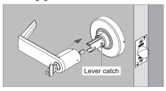
Install outside lever with KIL (key-in-lever) cylinder, ALX70 function
1. Insert key into cylinder.
2. Place the cylinder with key into the outside lever spindle until it bottoms out.
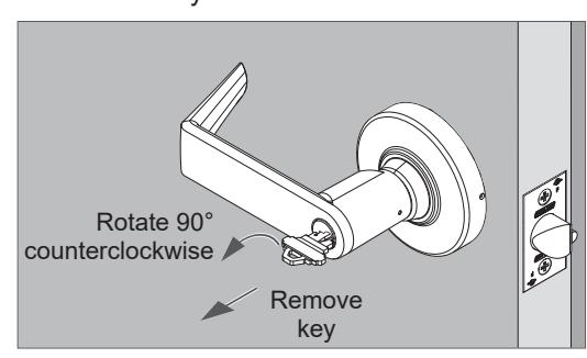
3. Turn the key <u>clockwise</u> until it stops. The key should be horizontal when it stops.
4. Remove cylinder and remove key from cylinder.
5. Adjust the keycam position using a flat screwdriver.

6. Place the cylinder assembly into the lever.
7. Insert the key and rotate 90 degrees clockwise.
8. With key still rotated 90 degrees clockwise, install the outside lever onto the spindle.
Be sure to engage the lever catch.
9. Rotate the key <u>counterclockwise</u> back to the starting position and remove the key.
- L IMPORTANT! The following steps apply ONLY to ALX70 locks. ALX70 locks include a unique cylinder tailpiece. The following steps must be used for correct cylinder installation and lock performance.
- L ALX70 locks require timing before cylinder installation. Follow these steps ONLY IF THE TIMING TOOL IS NOT AVAILABLE. If the timing tool is available, follow steps starting on page 9 .
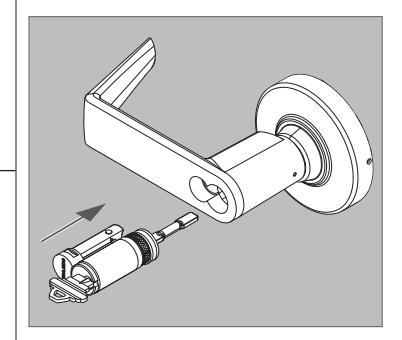
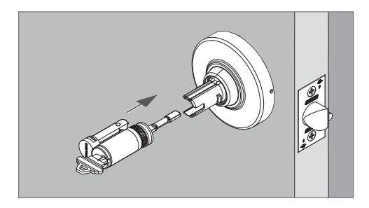
Install IC cylinder with outside lever, ALX70 function
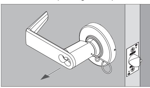
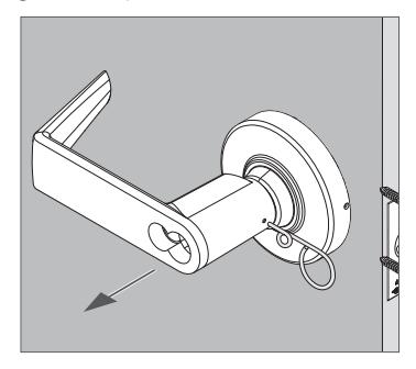
1. Remove the outside lever if it was pre-installed. Pull off the lever while pushing on the pin wrench.
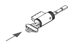
2. Install cylinder tailpiece.
Push tailpiece until it snaps into place.
FSIC cylinder:
Align notch with cap pin.
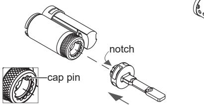
SFIC cylinder:
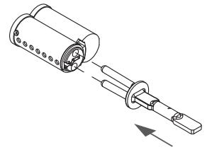
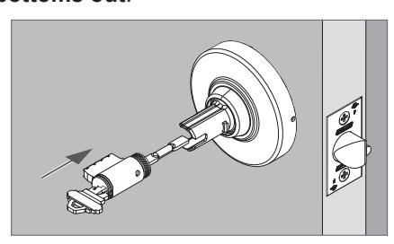
3. Insert the USER KEY into the cylinder.
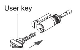
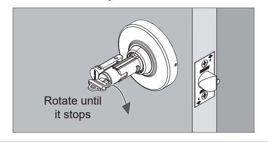
4. Place the cylinder with key into the outside lever spindle until it bottoms out .
5. Rotate the key clockwise until it stops. The key should be horizontal when it stops .
6. Rotate the key counterclockwise 180 degrees.
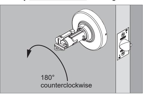
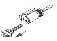
7. Remove cylinder and remove key from cylinder.
8. Install the lever onto the spindle. Be sure to engage the lever catch.
9. Insert the CONTROL KEY into the cylinder and turn 15 degrees clockwise.
10.Place the cylinder into the outside lever. Then, turn the key counterclockwise until it stops and remove the key.
LOCK DISASSEMBLY
Closed lever
- 1. Push the lever catch with the pin wrench.
- 2. Pull off the lever while pushing on the pin wrench.
Lever with turn (ALX40 and ALX44)
- 1. Push the lever catch with the pin wrench.
- 2. Pull off the lever while pushing on the pin wrench.
ALX40 shown
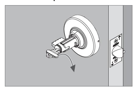
Lever with KIL cylinder
- 1. Insert key and turn 90 degrees clockwise.
- 2. Push the lever catch with the pin wrench.
- 3. Pull off the lever while pushing on the pin wrench.
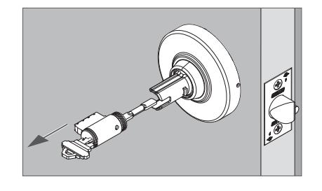
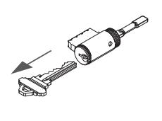
Lever with IC cylinder
- 1. Insert control key and turn 15 degrees clockwise.
- 2. Pull out the cylinder.
- 3. Push the lever catch with the pin wrench.
- 4. Pull off the lever while pushing on the pin wrench.
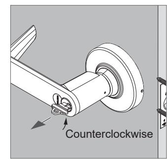
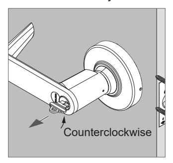
Rose
- 1. Rotate the rose counterclockwise approximately 10°.
- 2. Then, remove the rose.
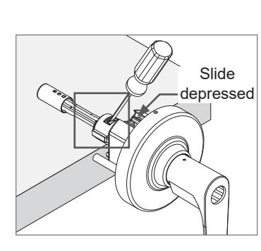
Button or plunger assembly removal
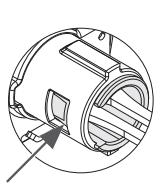
- 1. Place the chassis assembly on a table with the spindle resting on the table and the slide facing up as shown.
- 2. Push in and hold down the slide.
- 3. Use a flat screwdriver to press and push outward against the tab on the button sleeve (or plunger).
© Allegion 2019 Rev. 11/19
LOCK FUNCTIONAL TESTING
NOTICE
Test the lock with the door open to prevent being locked out.
| Customer Service (U.S.) | ||
|---|---|---|
| 1-877-671-7011 | www.allegion.com/us | |
| Customer Service (Canada) | ||
ALX10 Passage Function
- 1. Rotate inside lever. Rotation should be smooth and latch should retract.
- 2. Rotate outside lever. Rotation should be smooth and latch should retract.
ALX40 Bathroom/Bedroom Function
- 1. Push the inside button to lock the outside lever. Check that the outside lever is locked.
- 2. Rotate the inside lever to release the button and unlock the outside lever. Check that the outside lever is unlocked.
- 3. Push the inside push button to relock the outside lever. Check that the outside lever is locked.
- 4. Using a flat screwdriver, rotate the outside emergency turn to release the inside button. Check that the outside lever is unlocked.
- 5. The inside lever should always be unlocked and rotate freely.
ALX44 Hospital/Privacy Function
- 1. Push the inside push button to lock the outside lever. Check that the outside lever is locked.
- 2. Rotate the inside lever to release the button and unlock the outside lever. Check that the outside lever is unlocked.
- 3. Push the inside push button to relock the outside lever. Check that the outside lever is locked.
- 4. Rotate the outside emergency turn to release the inside button. Check that the outside lever is unlocked.
- 5. The inside lever should always be unlocked and rotate freely.
ALX50 Entrance/Office Function
- 1. Push the inside push button to lock the outside lever. Check that the outside lever is locked.
- 2. Rotate the inside lever to release the button and unlock the outside lever. Check that the outside lever is unlocked.
- 3. Push the inside push button to relock the outside lever. Check that the outside lever is locked.
- 4. Use the outside key to retract the latch and release the push button. Check that the outside lever is unlocked.
- 5. The inside lever should always be unlocked and rotate freely.
ALX53 Entrance Function
- 1. Push the inside push-turn button to lock the outside lever. Check that the outside lever is locked.
- 2. Rotate the inside lever to release the button and unlock the outside lever. Check that the outside lever is unlocked.
- 3. Push the inside push-turn button to relock the outside lever. Check that the outside lever is locked.
- 4. Use the outside key to retract the latch and release the push-turn button. Check that the outside lever is unlocked.
- 5. Push and turn the inside push-turn button 90 degrees clockwise to lock the outside lever. Check that the outside lever is locked.
- 6. Use the outside key to retract the latch. The push-turn button should stay in the locked (depressed and turned) position.
- 7. Rotate the inside push-turn button 90 degrees counterclockwise and then rotate the inside lever to release the inside push-turn button and unlock the outside lever. Check that the outside lever is unlocked.
- 8. The inside lever should always be unlocked and rotate freely.
ALX70 Classroom Function
- 1. Turn the outside key 180 degrees counterclockwise, then turn key 180 degrees clockwise (back to start position) to lock the outside lever. Check that the outside lever is locked.
- 2. Turn the outside key 180 degrees clockwise, then turn key 180 degrees counterclockwise (back to start position) to unlock the outside lever. Check that the outside lever is unlocked.
-
3. The inside lever should always be unlocked and rotate freely.
- Note : Key will not rotate 360 degrees.
ALX80 Storeroom Function
- 1. Check that the outside lever is fixed/locked.
- 2. Use the outside key to retract the latch.
- 3. The inside lever should always be unlocked and rotate freely.