Schlage AL Series Service Manual 106719
Open the original PDF document
View PDF

Contents
Introduction
Trim Assemblies
- Passage Latch Trim
- Exit Lock Trim
- Bath/Bedroom Privacy Lock Trim
- Hospital Privacy Lock Trim
- Entrance/Office Lock Trim
- Entrance Lock Trim
- Classroom Lock Trim
- Storeroom Lock Trim
- Faculty Restroom Lock Trim
- Single Dummy Trim
Trim Options
Chassis Assemblies
- AL10S Passage Lock Chassis Assembly
- AL25D Exit Lock Chassis Assembly
- AL40S Bath/Bedroom Lock Chassis Assembly
- AL44S Hospital Privacy Lock Chassis Assembly
- AL50PD Entrance /Office Lock Chassis Assembly
- AL53PD Entrance Lock Chassis Assembly
- AL70PD Classroom Lock Chassis Assembly
- AL80PD Storeroom Lock Chassis Assembly
- AL85PD Faculty Restroom Lock Chassis Assembly
Latches
Latch accessories and adapters
Strikes
Cylinder Options
- Standard Cylinders
- FSIC and SFIC Cylinders
- Full Size Interchangeable Core
- Small Format Interchangeable Core
- Interchangeable Core Related Parts and Levers
- Cylinder Conversion
Parts
Screws and Screw Packs
Door Handing
Ordering Procedure
Limited Warranty
Introduction
This manual contains a complete listing of AL-Series (Grade 2) cylindrical lock parts and assemblies manufactured by the Schlage Lock Company. This edition lists components of AL-Series locks manufactured after June, 2003.
Exploded views of chassis and trim are shown with parts for standard size doors, with accompanying charts to identify parts for replacement purposes. In addition, lock trim ordering procedures, general cylinder information, and all auxiliary components of the AL-Series cylindrical locks are included.
Schlage AL-Series lock parts are manufactured to close tolerances and are interchangeable between functions. Conversion of functions may be performed by identifying necessary substitution parts and following assembly as indicated on the lock drawings.
| Standard Features* | |||
|---|---|---|---|
| Certifications | ANSI/BHMA Certified A156.2, 2003, Series 4000, Grade 2, UL listed for 3-hour fire door | ||
| Latch | 1Z" x 2Z\v", Square corner faceplate, 1" housing diameter, Z\x" throw | ||
| Strike | 1Z\v" x 4M", ANSI, Square corner, no box | ||
| Backset | 2C\v" | ||
| Cylinder | 6-Pin solid brass, keyed 6-pin, S123 keyway, keyed different (KD)** | ||
| Door Range | 1C" – 1M" | ||
| Keys | Two nickel silver cut keys per lock, 6-pin, S123 section** | ||
- * Locks are furnished with standard features unless otherwise specified.
- ** Items specified in C keyway will be furnished with cylinder keyed 5-pin and with 5-pin keys unless otherwise specified.
Lock Assembly Drawing Index
The Lock Assembly Drawing Index provides illustrations and textual descriptions of available functions. Page numbers for full trim and chassis drawings are referenced.
| Function | ANSI A156.2, 2003, Series 4000, Grade 2 | Trim | Chassis | |||
|---|---|---|---|---|---|---|
| Schlage | ANSI | Description | Outside function | Inside function | Page | Page |
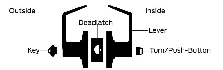
| AL10S | F75 | Passage Latch | Lever is always unlocked. |
Lever is always unlocked and is always
free for immediate egress. |
9 | 22 |
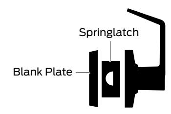
| AL25D | Exit Lock | Blank plate outside. |
Lever is always unlocked and is always
free for immediate egress. |
10 | 23 | |
| AL40S | F76 |
Bath/Bedroom
Privacy Lock |
Outside lever is locked by inside
push-button. May be unlocked from outside with small screwdriver (not included), or with 35-250 emergency key |
Push-button locks outside lever.
Turning inside lever or closing door releases button. Inside lever is always free for immediate egress. |
11 | 24 |
Note: Any function with a deadlatch locks the latchbolt when door is closed. See page 5 for identification.
* AL85 functions are not available in Full Size or Small Format Interchangeable cores.
| Function | ANSI A156.2, 2003, Series 4000, Grade 2 | Trim | Chassis | ||||
|---|---|---|---|---|---|---|---|
| Schlage | ANSI | Description | Outside function | Inside function | Page | Page | |
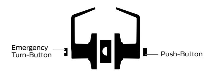
| AL44S |
Hospital
Privacy Lock |
Outside lever is locked by inside
push-button. Unlocked from outside by turning emergency turn-button. |
Push-button locks outside lever.
Turning inside lever or closing door releases button. Inside lever is always free for immediate egress. |
12 | 25 | ||
| AL50PD | F82 |
Entrance/
Office Lock |
Outside lever is locked by inside
push-button. Unlocked from outside with key. |
Push-button locks outside lever.
Turning inside lever releases button. Inside lever is always free for immediate egress. |
13 | 26 | |
| AL53PD | F109 | Entrance Lock |
Turn/Push-Button: Outside lever is
locked by pushing and turning the inside turn/push-button. Key must be used until turn/push-button is unlocked. Push-Button: Outside lever is locked by pushing the inside push-button. Key must be used until push-button is unlocked. Unlocked from outside with key. |
Turn/Push-Button:
Outside lever is locked by pushing and turning the inside turn/push-button until button is manually unlocked. Push-Button: Pushing button locks outside lever. Turning inside lever releases button. Inside lever is always free for immediate egress. |
14 | 27 | |
| AL70PD | F84 |
Classroom
Lock |
Outside lever is locked and unlocked by
key outside. |
Inside lever is always unlocked and free
for immediate egress. |
15 | 28 | |
| AL80PD | F86 |
Storeroom
Lock |
Outside lever is fixed. Entrance by key
only. |
Inside lever is always unlocked and free
for immediate egress. |
16 | 29 | |
| AL85PD * | F93 |
Faculty
Restroom Lock with Indicator Cylinder |
Outside lever is fixed. Entrance by key
only. When push-button is activated from inside, only the emergency master key will allow entrance. |
Push-button activates occupancy
indicator, allowing only emergency master key to operate. Turning lever or closing door releases button. Spanner button rotation provides lock-out feature. Inside lever is always free for immediate egress. |
17 | 30 | |
| AL170 |
Single Dummy
Trim |
Dummy trim for one side of door. Use as
door pull or as matching inactive trim. |
18 | — | |||
Note: Any function with a deadlatch locks the latchbolt when door is closed. See page 5 for identification.
* AL85 functions are not available in Full Size or Small Format Interchangeable cores.
- Passage Latch Trim
- Exit Lock Trim
- Bath/Bedroom Privacy Lock Trim
- Hospital Privacy Lock Trim
- Entrance/Office Lock Trim
- Entrance Lock Trim
- Classroom Lock Trim
- Storeroom Lock Trim
- Faculty Restroom Lock Trim
- Single Dummy Trim
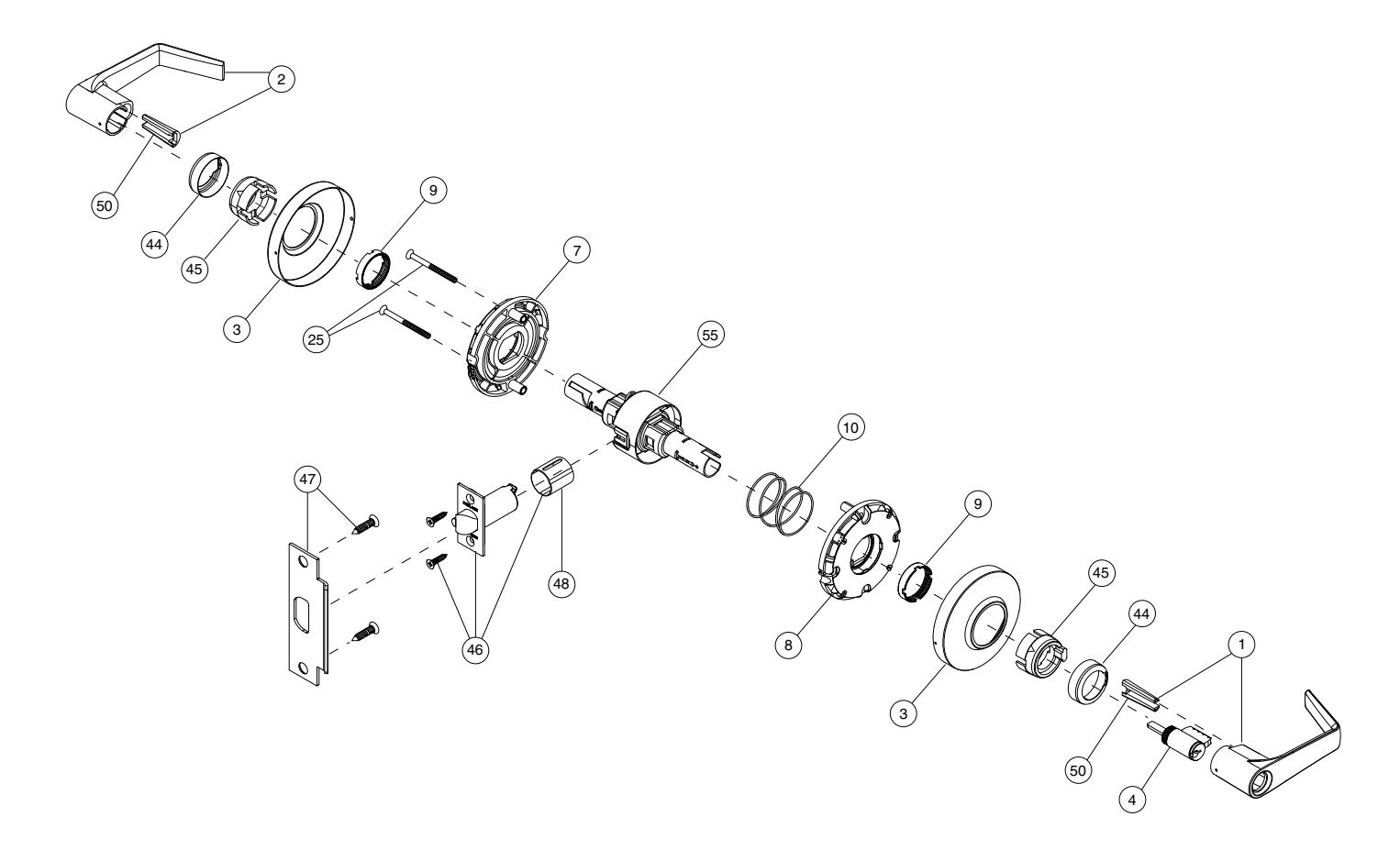
Passage Latch Trim
AL10S
| No. | Description | Part no. |
|---|---|---|
| 2 | Closed Lever (2) | 51-025* |
| 3 | Rose (2) | 04-060 |
| 7 | Inside Spring Cage | A100-053** |
| 8 | Outside Spring Cage | A100-054** |
| 9 | Castle Nut (2) | C604-354 |
| 10 | Anchor Spring | C503-308 |
| 25 | Spring Cage Mounting Screw (2) | C604-395 |
| No. | Description | Part no. |
|---|---|---|
| 44 | Driver Cap | A700-041** |
| 45 | Driver Bushing | A700-039** |
| 46 | Springlatch | 11-116 |
| 47 | Strike, ANSI standard, no box | 10-025 |
| 48 | Latch Housing Sleeve (for M" housing only) | G506-815 |
| 50 | Lever insert (2) | A700-044** |
| 55 | AL10 Chassis | 61-210-134*** |
- * For locks manufactured after June 2003. See Levers on page 19 for a complete list of lever part numbers.
- ** For locks manufactured after May 2002.
- *** Chassis part number is for reference only.
Exit Lock Trim
AL25D
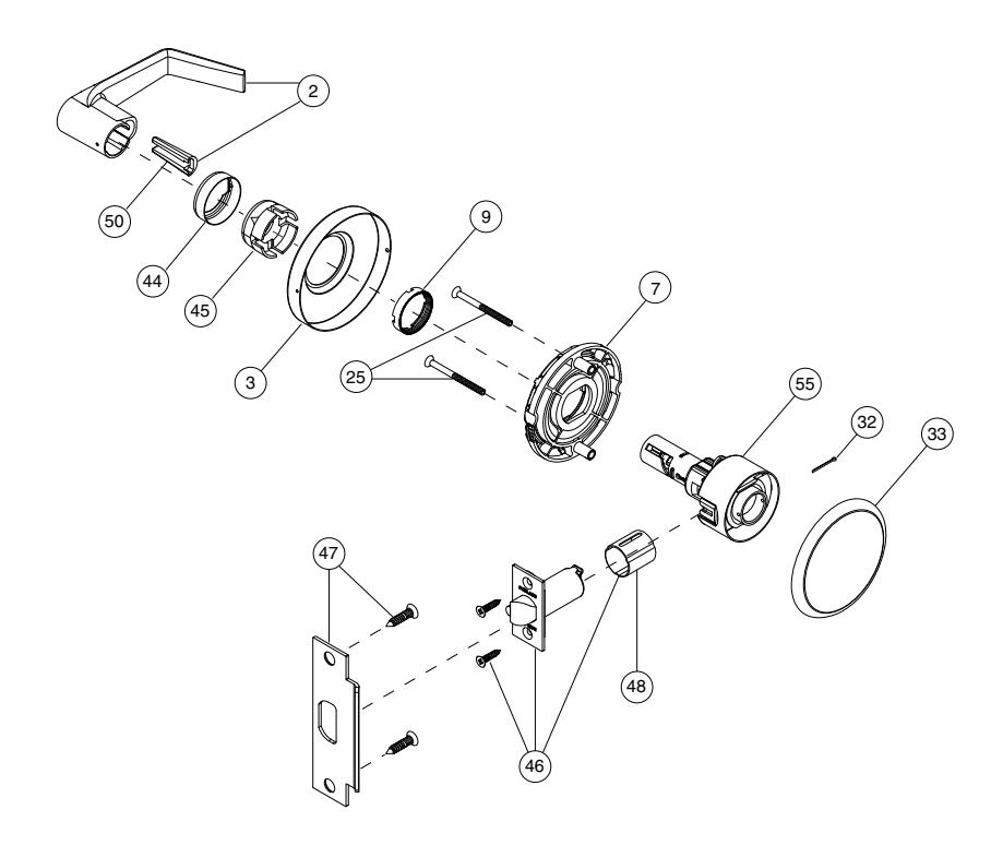
| No. | Description | Part no. |
|---|---|---|
| 2 | Closed Lever | 51-025* |
| 3 | Rose | 04-060 |
| 7 | Inside Spring Cage | A100-053** |
| 9 | Castle Nut | C604-354 |
| 25 | Spring Cage Mounting Screws (2) | C604-395 |
| 32 | Cotter Pin | C604-273 |
| 33 | Rose, Outside Blank | C604-402 |
| No. | Description | Part no. |
|---|---|---|
| 44 | Driver Cap | A700-041** |
| 45 | Driver Bushing | A700-039** |
| 46 | Deadlatch | 11-096 |
| 47 | Strike, ANSI standard, no box | 10-025 |
| 48 | Latch Housing Sleeve (M" housing only) | G506-815 |
| 50 | Lever insert | A700-044* |
| 55 | AL25 Chassis | 61-225-134*** |
- * For locks manufactured after June 2003. See Levers on page 19 for a complete list of lever part numbers.
- ** For locks manufactured after May 2002.
- *** Chassis part number is for reference only.
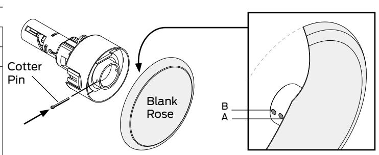
AL25 Door Thickness Adjustment
| Door Thickness | Blank Rose Adjustment |
|---|---|
| 1C" | Place cotter pin at hole A on the Blank Rose. |
| 1C\v" | Place cotter pin at hole B on the Blank Rose. |
| 2" |
Non-standard door thickness for AL25.
Specify 2" door thickness on order. If cotter pin adjustment is necessary, place at hole B. |
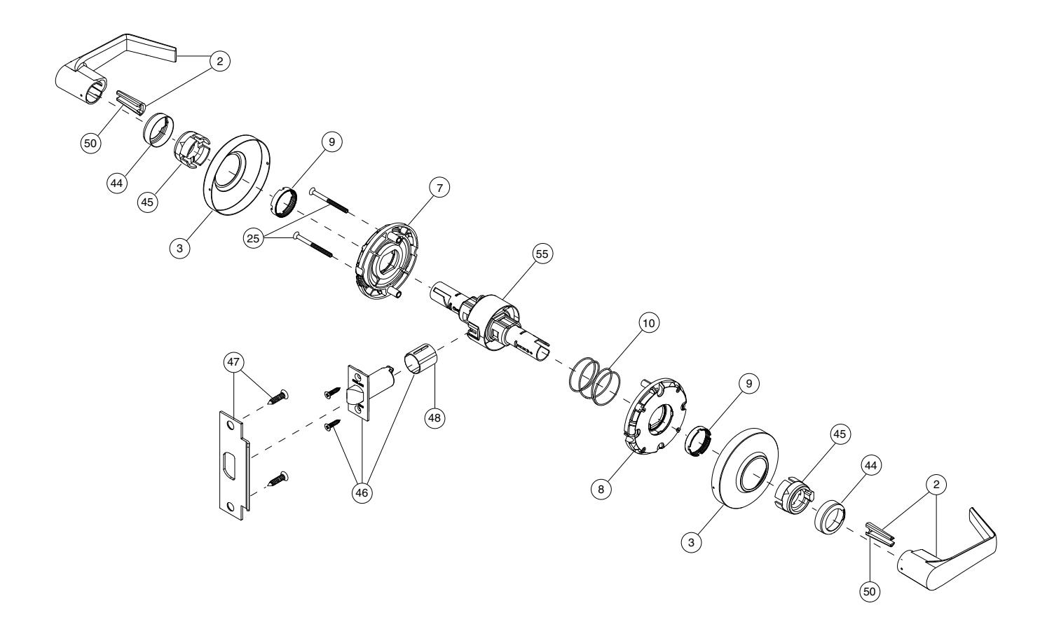
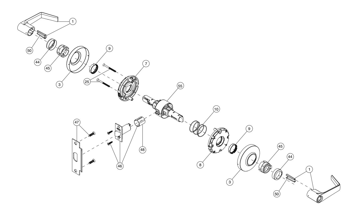
Bath/Bedroom Privacy Lock Trim
AL40S

| No. | Description | Part no. |
|---|---|---|
| 1 | Open Lever (2) | 51-026* |
| 3 | Rose (2) | 04-060 |
| 7 | Inside Spring Cage | A100-053** |
| 8 | Outside Spring Cage | A100-054** |
| 9 | Castle Nut (2) | C604-354 |
| 10 | Anchor Spring | C503-308 |
| 25 | Spring Cage Mounting Screws (2) | C604-395 |
| No. | Description | Part no. |
|---|---|---|
| 44 | Driver Cap | A700-041** |
| 45 | Driver Bushing | A700-039** |
| 46 | Springlatch | 11-116 |
| 47 | Strike, ANSI standard, no box | 10-025 |
| 48 | Latch Housing Sleeve (for M" housing only) | G506-815 |
| 50 | Lever insert (2) | A700-044** |
| 55 | AL40 Chassis | 61-240-134*** |
* For locks manufactured after June 2003. See Levers on page 19 for a complete list of lever part numbers.
** For locks manufactured after May 2002.
*** Chassis part number is for reference only.
Hospital Privacy Lock Trim
AL44S
| No. | Description | Part no. |
|---|---|---|
| 1 | Open Lever (2) | 51-026* |
| 3 | Rose (2) | 04-060 |
| 7 | Inside Spring Cage | A100-053** |
| 8 | Outside Spring Cage | A100-054** |
| 9 | Castle Nut (2) | C604-354 |
| 10 | Anchor Spring | C503-308 |
| 25 | Spring Cage Mounting Screws (2) | C604-395 |
| No. | Description | Part no. |
|---|---|---|
| 44 | Driver Cap | A700-041** |
| 45 | Driver Bushing | A700-039** |
| 46 | Springlatch | 11-116 |
| 47 | Strike, ANSI standard, no box | 10-025 |
| 48 | Latch Housing Sleeve (for M" housing only) | G506-815 |
| 50 | Lever insert (2) | A700-044* |
| 55 | AL44 Chassis | 61-240-134*** |
- * For locks manufactured after June 2003. See Levers on page 19 for a complete list of lever part numbers.
- ** For locks manufactured after May 2002.
- *** Chassis part number is for reference only.
Entrance/Office Lock Trim
AL50PD

| No. | Description | Part no. |
|---|---|---|
| 1 | Open Lever (2) | 51-026* |
| 3 | Rose (2) | 04-060 |
| 4 | Cylinder | 21-020 |
| 7 | Inside Spring Cage | A100-053** |
| 8 | Outside Spring Cage | A100-054** |
| 9 | Castle Nut (2) | C604-354 |
| 10 | Anchor Spring | C503-308 |
| 25 | Spring Cage Mounting Screws (2) | C604-395 |
| No. | Description | Part no. |
|---|---|---|
| 44 | Driver Cap | A700-041** |
| 45 | Driver Bushing | A700-039** |
| 46 | Deadlatch | 11-096 |
| 47 | Strike, ANSI standard, no box | 10-025 |
| 48 | Latch Housing Sleeve (for M" housing only) | G506-815 |
| 50 | Insert (2) | A700-044** |
| 55 | AL50 Chassis | 61-253-134*** |
- * For locks manufactured after June 2003. See Levers on page 19 for a complete list of lever part numbers.
- ** For locks manufactured after May 2002.
- *** Chassis part number is for reference only.
Entrance Lock Trim
AL53PD

| No. | Description | Part no. |
|---|---|---|
| 1 | Open Lever (2) | 51-026* |
| 3 | Rose (2) | 04-060 |
| 4 | Cylinder | 21-020 |
| 7 | Inside Spring Cage | A100-053** |
| 8 | Outside Spring Cage | A100-054** |
| 9 | Castle Nut (2) | C604-354 |
| 10 | Anchor Spring | C503-308 |
| 25 | Spring Cage Mounting Screws (2) | C604-395 |
| No. | Description | Part no. |
|---|---|---|
| 44 | Driver Cap | A700-041** |
| 45 | Driver Bushing | A700-039** |
| 46 | Deadlatch | 11-096 |
| 47 | Strike, ANSI standard, no box | 10-025 |
| 48 | Latch Housing Sleeve (for M" housing only) | G506-815 |
| 50 | Insert (2) | A700-044** |
| 55 | AL53 Chassis | 61-253-134*** |
- * For locks manufactured after June 2003. See Levers on page 19 for a complete list of lever part numbers.
- ** For locks manufactured after May 2002.
- *** Chassis part number is for reference only.
Classroom Lock Trim
AL70PD
| No. | Description | Part no. |
|---|---|---|
| 1 | Open Lever | 51-026* |
| 2 | Closed Lever | 51-025* |
| 3 | Rose (2) | 04-060 |
| 4 | Cylinder | 21-020 |
| 7 | Inside Spring Cage | A100-053** |
| 8 | Outside Spring Cage | A100-054** |
| 9 | Castle Nut (2) | C604-354 |
| 10 | Anchor Spring | C503-308 |
| No. | Description | Part no. |
|---|---|---|
| 25 | Spring Cage Mounting Screws (2) | C604-395 |
| 44 | Driver Cap | A700-041** |
| 45 | Driver Bushing | A700-039** |
| 46 | Deadlatch | 11-096 |
| 47 | Strike, ANSI standard, no box | 10-025 |
| 48 | Latch Housing Sleeve (for M" housing only) | G506-815 |
| 50 | Lever insert (2) | A700-044** |
| 55 | AL70 Chassis | 61-270-134*** |
- * For locks manufactured after June 2003. See Levers on page 19 for a complete list of lever part numbers.
- ** For locks manufactured after May 2002.
- *** Chassis part number is for reference only.
Storeroom Lock Trim
AL80PD

| No. | Description | Part no. |
|---|---|---|
| 1 | Open Lever | 51-026* |
| 2 | Closed Lever | 51-025* |
| 3 | Rose (2) | 04-060 |
| 4 | Cylinder | 21-020 |
| 7 | Inside Spring Cage | A100-053** |
| 8 | Outside Spring Cage | A100-054** |
| 9 | Castle Nut (2) | C604-354 |
| 10 | Anchor Spring | C503-308 |
| No. | Description | Part no. |
|---|---|---|
| 25 | Spring Cage Mounting Screws (2) | C604-395 |
| 44 | Driver Cap | A700-041** |
| 45 | Driver Bushing | A700-039** |
| 46 | Deadlatch | 11-096 |
| 47 | Strike, ANSI standard, no box | 10-025 |
| 48 | Latch Housing Sleeve (for M" housing only) | G506-815 |
| 50 | Lever insert (2) | A700-044** |
| 55 | AL80 Chassis | 61-280-134*** |
- * For locks manufactured after June 2003. See Levers on page 19 for a complete list of lever part numbers.
- ** For locks manufactured after May 2002.
- *** Chassis part number is for reference only.
Faculty Restroom Lock Trim
AL85PD
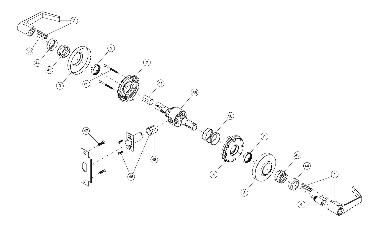
| No. | Description | Part no. |
|---|---|---|
| 1 | Open Lever | 51-026* |
| 2 | Closed Lever | 51-025* |
| 3 | Rose (2) | 04-060 |
| 4 | Cylinder | 21-021 |
| 7 | Inside Spring Cage | A100-053** |
| 8 | Outside Spring Cage | A100-054** |
| 9 | Castle Nut (2) | C604-354 |
| 10 | Anchor Spring | C503-308 |
| 25 | Spring Cage Mounting Screws (2) | C604-395 |
| No. | Description | Part no. |
|---|---|---|
| 41 | Sleeve, Spindle | A700-003 |
| 44 | Driver Cap | A700-041** |
| 45 | Driver Bushing | A700-039** |
| 46 | Deadlatch | 11-096 |
| 47 | Strike, ANSI standard, no box | 10-025 |
| 48 | Latch Housing Sleeve (for M" housing only) | G506-815 |
| 50 | Lever insert (2) | A700-044** |
| 55 | AL85 Chassis | 61-285-134*** |
- * For locks manufactured after June 2003. See Levers on page 19 for a complete list of lever part numbers.
- ** For locks manufactured after May 2002.
- *** Chassis part number is for reference only.
Single Dummy Trim
AL170
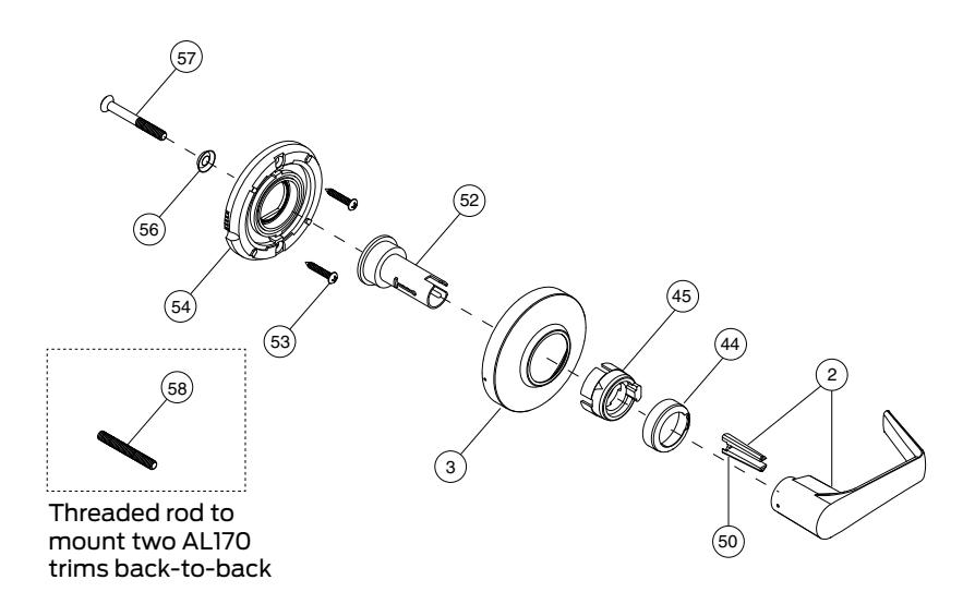
| No. | Description | Part no. |
|---|---|---|
| 2 | Closed Lever | 51-025* |
| 3 | Rose | 04-060 |
| 7 | Inside Spring Cage | A100-053** |
| 44 | Driver Cap | A700-041** |
| 45 | Driver Bushing | A700-039** |
| 50 | Lever insert | A700-044** |
| No. | Description | Part no. |
|---|---|---|
| 52 | Spindle and Hub | A710-007 |
| 53 | Mounting Screws (2) | L583-133 |
| 54 | Housing, Spring Cage | C604-400 |
| 56 | Washer | A501-171 |
| 57 | Thru Bolt | A501-746 |
| 58 | Spindle, Threaded Rod | A501-167 |
* For locks manufactured after June 2003. See Levers on page 19 for a complete list of lever part numbers.
** For locks manufactured after May 2002.
Trim Options
Levers
| Description | Part number | Manufactured date |
|---|---|---|
| Closed lever and insert | 51-021 | Before June 2003 |
| Open lever and insert | 51-023 | |
| Closed lever and insert | 51-025 | After June 2003 |
| Open lever and insert | 51-026 | |
| Full size core lever and insert | 51-022 | – |
| Small format core lever and insert | 51-024 |
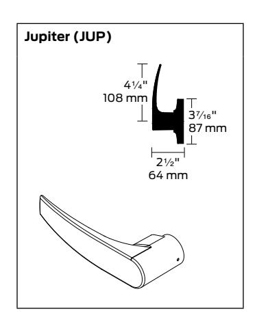
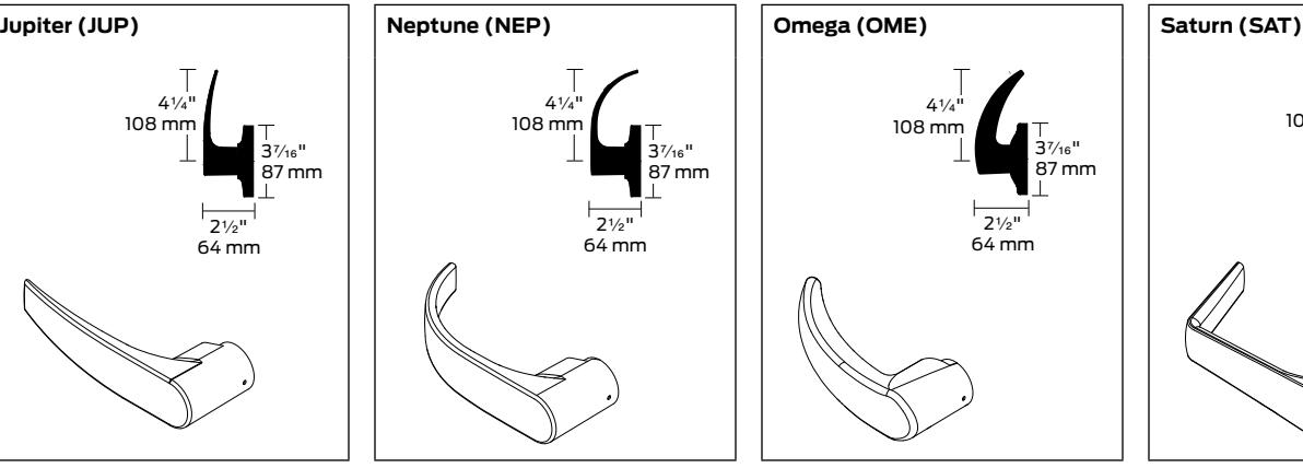
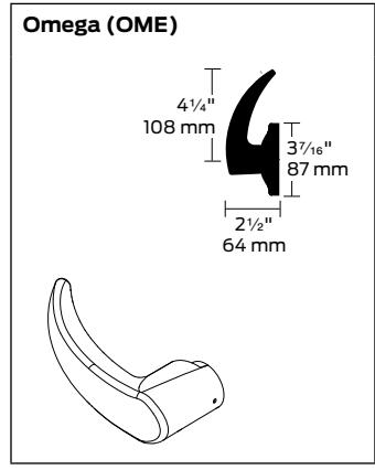
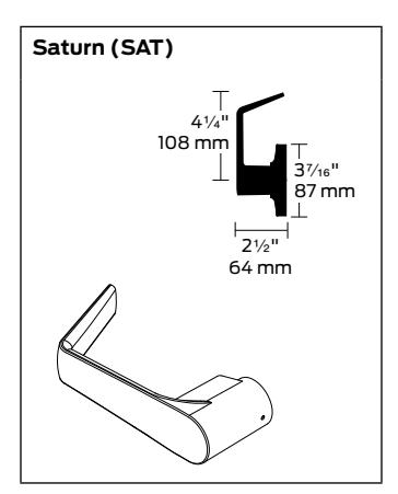
Lever Designs
Levers are pressure cast zinc. All levers are ADA Accessibility compliant. Neptune, Omega and Saturn lever designs meet California code for Z\x" or less return to the door.
Lever Inserts
| Description | Part number |
|---|---|
| Lever insert for 1C" -1M" doors * | A700-015 |
| Lever insert for 1C" -1M" doors ** | A700-044 |
| Lever insert for SFIC | A700-045 |
| Lever insert for interchangeable core with 1C" -1M" doors *** | A700-047 |
- * For locks manufactured before May 2002
- ** For locks manufactured after May 2002.
- *** For locks manufactured after March 2003.
Tactile Warning
Available on Saturn design levers only. Applied to outside lever only unless otherwise specified.
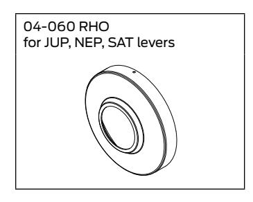
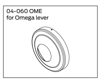
Roses
Rose trims are available in wrought brass or bronze.
Trim Finishes
Schlage AL-Series lock products are available in a range of durable, top-quality finishes. Most are available with a clear coating that protects against damaging environmental factors, including sea air, high humidity, or corrosive vapors.
The antimicrobial coating on Schlage AL-Series locks works to protect the hardware's surface by inhibiting the growth of bacteria, mold and mildew. The coating is made using ionic silver (AG+), a single atom that is missing one orbital electron that interacts with the bonding sites on the microbe surface. The result is that silver ions surround bacterial cells, blocking food and respiration supply, and slowing bacterial growth.
Finishes are coded according to the Builders Hardware Manufacturers Association (BHMA). The nearest old U.S. equivalent code designations are shown in parentheses.
| Code | Description | |
|---|---|---|
| 605 | (US 3) | Bright brass |
| 606 | (US 4) | Satin brass |
| 609 | (US 5) | Antique brass |
| 612 | (US 10) | Satin bronze |
| 613 | (US 10B) | Oil rubbed bronze |
| Code | Description | |
|---|---|---|
| 619 | (US 15) | Satin nickel |
| 625 | (US 25) | Birght chromium plated |
| 626 | (US 26D) | Satin chromium plated |
| 626AM | Antimicrobial coating on satin chromium | |
| 643e | (US 11) | Aged bronze (e=equivalent to bhma std) |
- Passage Lock Chassis Assembly
- Exit Lock Chassis Assembly
- Bath/Bedroom Lock Chassis Assembly
- Hospital Privacy Lock Chassis Assembly
- Entrance /Office Lock Chassis Assembly
- Entrance Lock Chassis Assembly
- Classroom Lock Chassis Assembly
- Storeroom Lock Chassis Assembly
- Faculty Restroom Lock Chassis Assembly
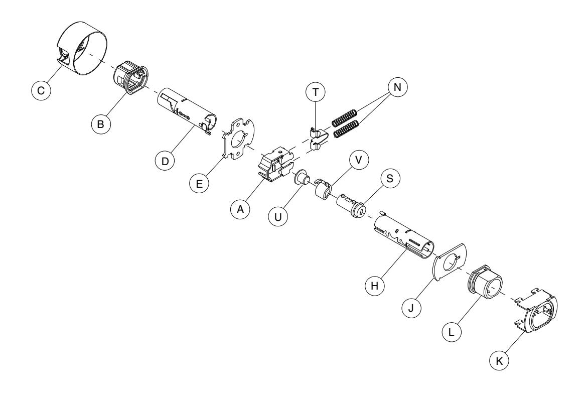
Passage Lock Chassis Assembly
AL10S
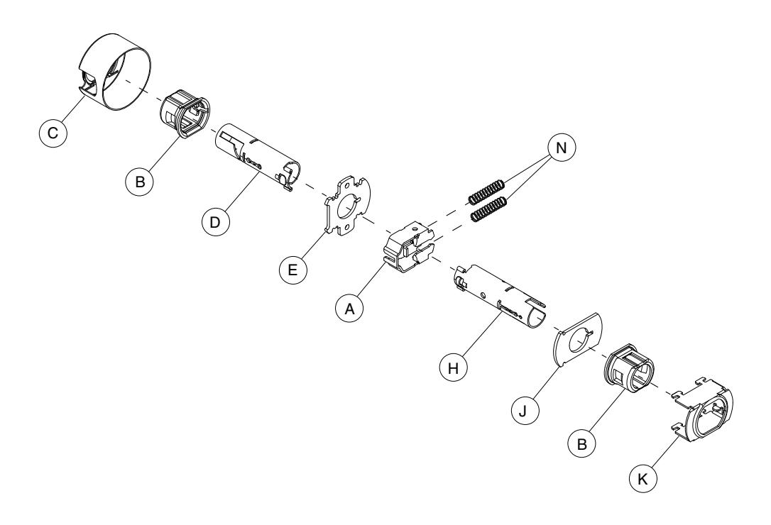
| Letter | Description | Part no. |
|---|---|---|
| A | Slide, Non-Restoring | A590-181 |
| B | Hub (2) | A700-046 |
| C | Housing, Chassis | A700-057 |
| D | Spindle and Catch, Inside | A710-004 |
| E | Plate, Hub, Inside | A501-305 |
| Letter | Description | Part no. |
|---|---|---|
| H | Spindle and Catch, Outside | A710-020 |
| J | Plate, Outside | A700-004 |
| K | Frame, Hub | A700-056 |
| N | Spring, Slide (2) | A501-311 |
Exit Lock Chassis Assembly
AL25D
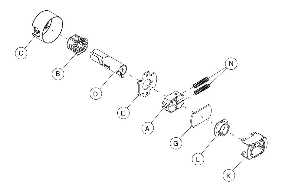
| Letter | Description | Part no. |
|---|---|---|
| A | Slide, Non-Restoring | A590-181 |
| B | Hub | A700-046 |
| C | Housing, Chassis | A700-057 |
| D | Spindle and Catch, Inside | A710-004 |
| E | Plate, Hub, Inside | A501-305 |
| Letter | Description | Part no. |
|---|---|---|
| G | Plate, AL25 Outside | A501-874 |
| K | Frame, Hub | A700-056 |
| L | Hub, AL25 Outside | A700-016 |
| N | Spring, Slide (2) | A501-311 |
Bath/Bedroom Lock Chassis Assembly
AL40S
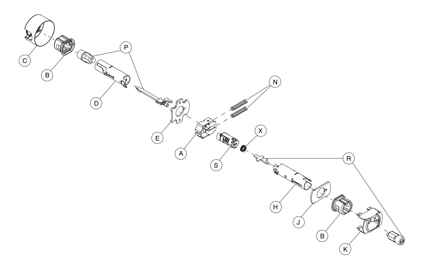
| Letter | Description | Part no. |
|---|---|---|
| A | Slide, Restoring | A590-180 |
| B | Hub (2) | A700-046 |
| C | Housing, Chassis | A700-057 |
| D | Spindle and Catch, Inside | A710-004 |
| E | Plate, Hub, Inside | A501-305 |
| H | Spindle and Catch, Outside | A710-020 |
| J | Plate, Outside | A700-004 |
| Letter | Description | Part no. |
|---|---|---|
| K | Frame, Hub | A700-056 |
| N | Spring, Slide (2) | A501-311 |
| P | Plunger and Button, Inside | 51-039 |
| R | Plunger and Button, Outside | 51-040 |
| S | Cam and Spring | A301-402 |
| X | Spring | A700-036 |
Hospital Privacy Lock Chassis Assembly
AL44S
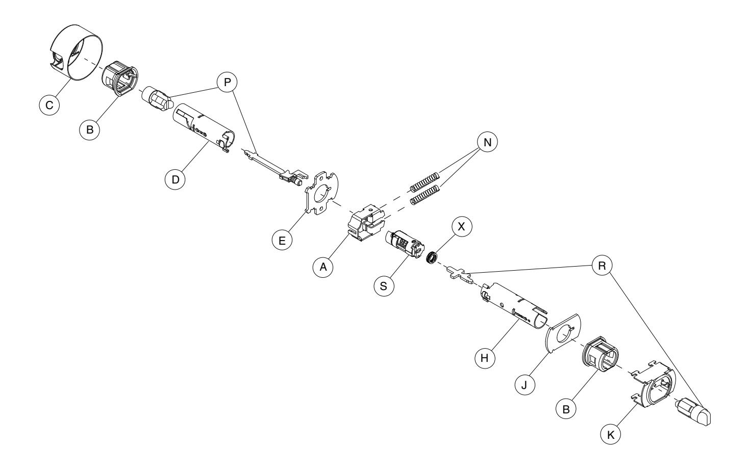
| Letter | Description | Part no. |
|---|---|---|
| A | Slide, Restoring | A590-180 |
| B | Hub (2) | A700-046 |
| C | Housing, Chassis | A700-057 |
| D | Spindle and Catch, Inside | A710-004 |
| E | Plate, Hub, Inside | A501-305 |
| H | Spindle and Catch, Outside | A710-020 |
| J | Plate, Outside | A700-004 |
| Letter | Description | Part no. |
|---|---|---|
| K | Frame, Hub | A700-056 |
| N | Spring, Slide (2) | A501-311 |
| P | Plunger and Button, Inside | 51-039 |
| R | Plunger and Button, Outside | 51-041 |
| S | Cam and Spring | A301-402 |
| X | Spring | A700-036 |
Entrance /Office Lock Chassis Assembly
AL50PD
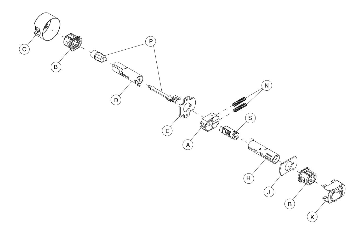
| Letter | Description | Part no. |
|---|---|---|
| A | Slide, Non-Restoring * | A590-181 |
| B | Hub | A700-046 |
| C | Housing, Chassis | A700-057 |
| D | Spindle and Catch, Inside | A710-004 |
| E | Plate, Hub, Inside | A501-305 |
| H | Spindle and Catch, Outside | A710-001 |
| Letter | Description | Part no. |
|---|---|---|
| J | Plate, Outside | A700-004 |
| K | Frame, Hub | A700-056 |
| N | Spring, Slide (2) | A501-311 |
| P | Plunger and Button | 51-039 |
| S | Cam and Spring | A301-402 |
* AL50PD is available with restoring slide. Order by AL50PD x XA11-297.
Entrance Lock Chassis Assembly
AL53PD
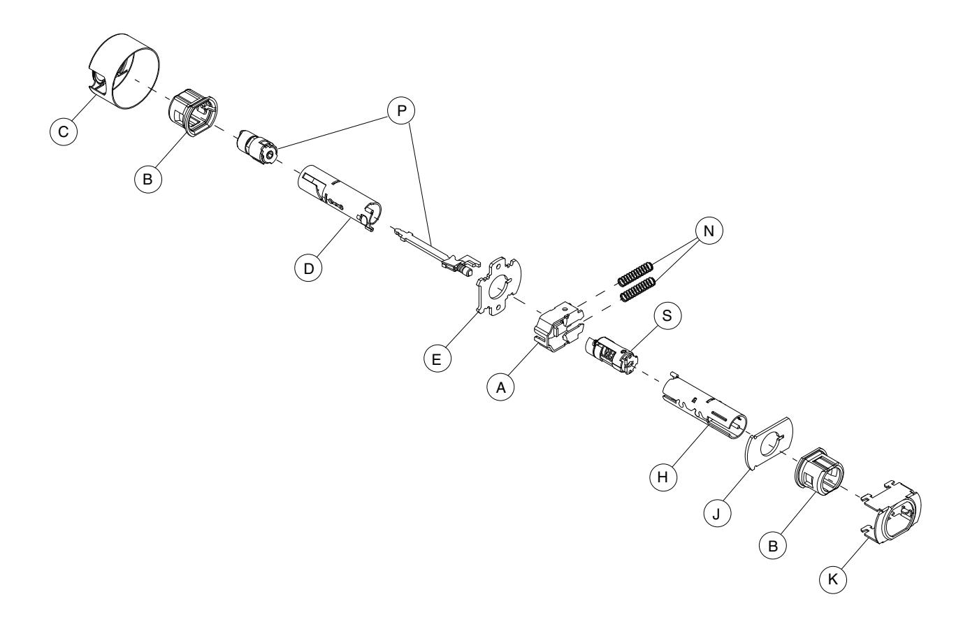
| Letter | Description | Part no. |
|---|---|---|
| A | Slide, Non-Restoring * | A590-181 |
| B | Hub | A700-046 |
| C | Housing, Chassis | A700-057 |
| D | Spindle and Catch, Inside | A710-004 |
| E | Plate, Hub, Inside | A501-305 |
| H | Spindle and Catch, Outside | A710-001 |
| Letter | Description | Part no. |
|---|---|---|
| J | Plate, Outside | A700-004 |
| K | Frame, Hub | A700-056 |
| N | Spring, Slide (2) | A501-311 |
| P | Plunger and Button | 51-037 |
| S | Cam and Spring | A301-402 |
* AL53PD is available with restoring slide. Order by AL50PD x XA11-297.
Classroom Lock Chassis Assembly
AL70PD
| Letter | Description | Part no. |
|---|---|---|
| A | Slide, Non-Restoring | A590-159 |
| B | Hub | A700-046 |
| C | Housing, Chassis | A700-057 |
| D | Spindle and Catch, Inside | A710-004 |
| E | Plate, Hub, Inside | A501-305 |
| H | Spindle and Catch, Outside | A710-001 |
| J | Plate, Outside | A700-004 |
| Letter | Description | Part no. |
|---|---|---|
| K | Frame, Hub | A700-056 |
| L | Hub, AL70 Outside | A700-014 |
| N | Spring, Slide (2) | A501-311 |
| S | Plug, Cam | A501-721 |
| T | Spring Seat | A508-597 |
| U | Spacer, Cam | A501-791 |
| V | Cam, Spiral | A700-017 |
Storeroom Lock Chassis Assembly
AL80PD
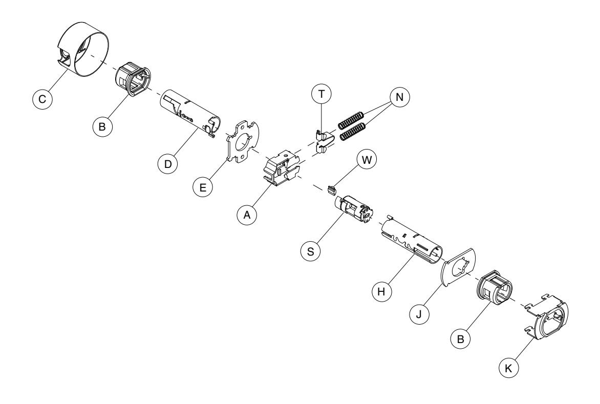
| Letter | Description | Part no. |
|---|---|---|
| A | Slide, Non-Restoring | A590-159 |
| B | Hub (2)w | A700-046 |
| C |
Housing, Chassis
A700-057 |
|
| D | Spindle and Catch, Inside | A710-004 |
| E | Plate, Hub, Inside | A501-305 |
| H | Spindle and Catch, Outside | A710-001 |
| Letter | Description | Part no. |
|---|---|---|
| J | Plate, Outside | A501-901 |
| K | Frame, Hub | A700-056 |
| N | Spring, Slide (2) | A501-311 |
| S | Cam and Spring | A201-370 |
| T | Spring Seat | A508-597 |
| W | Wedge, Spindle | A501-615 |
Faculty Restroom Lock Chassis Assembly
AL85PD

| Letter | Description | Part no. |
|---|---|---|
| A | Slide, Restoring | A590-158 |
| B | Hub | A700-046 |
| C | Housing, Chassis | A700-057 |
| D | Spindle and Catch, Inside | A710-004 |
| E | Plate, Hub, Inside | A501-305 |
| H | Spindle and Catch, Outside | A710-001 |
| J | Plate, Outside | A501-901 |
| Letter | Description | Part no. |
|---|---|---|
| K | Frame, Hub | A700-056 |
| N |
Spring, Slide (2)
A501-311 |
|
| P | Plunger and Button | 51-038 |
| S | Cam and Spring | A301-402 |
| T |
Spring Seat
A508-597 |
|
| W | Wedge, Spindle | A501-615 |
Latches
| Part number |
Backset
Housing |
Description | ||
|---|---|---|---|---|
| Springlatch | Deadlatch | diameter | ||
| 11-068 | 11-085 | 2C" | M" | Square corner, 1" x 2Z\v" |
| 11-069 | 11-088 | Z\v" radius round corner, 1" x 2Z\v" | ||
| 11-110 | 11-104 | 1" | 1" circular drive-in, (605 and 626 finish only) | |
| 11-111 | 11-091 | 2C\v" | M" | Square corner, 1" x 2Z\v" |
| 11-112 | 11-092 | Z\v" radius round corner, 1" x 2Z\v" | ||
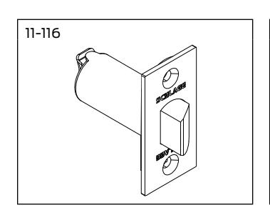
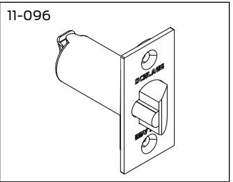
| 11-116 | 11-096 |
Square corner, 1Z" x 2Z\v", standard
1" |
||
| 11-113 | 11-105 | 1" circular drive-in, (605 and 626 finish only) | ||
| 11-118 | 11-103 | 3C\v" |
Square corner, 1Z" x 2Z\v"
1" |
|
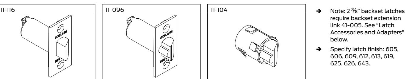
- require backset extension link 41-005. See "Latch Accessories and Adapters" below.
- Î Specify latch finish: 605, 606, 609, 612, 613, 619, 625, 626, 643.
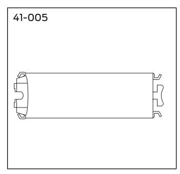
Latch accessories and adapters
| Part number | Description |
|---|---|
| 37-001 | Metal door reinforcement kit for M" and 1" diameter housings. (Specify door thickness) |
| 39-030 * | Adapts a square corner latch and a 2 C\v" high square corner strike to a Z\x" rabbeted door and frame preparation |
| 41-005 ** | 5" Backset extension link (must be used with 2Z" backset latches) |
| A501-565 | Reinforcement for non-reinforced metal doors 1C" thick. Fits both M" and 1" diameter housings |
| A501-566 | Reinforcement for non-reinforced metal doors 1C\v" thick. Fits both M" and 1" diameter housings |
| A501-567 | 3Z\x" long latch housing sleeve, reinforcement for joint between latch and backset link, or to hold latch in metal doors |
| A501-878 | Faceplate adapter to adapt 1" faceplate to 1Z" door preparation |
| G506-815 | 1" long latch housing sleeve to adapt M" diameter housing to 1" latch bore |
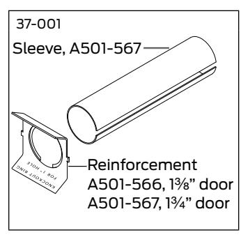
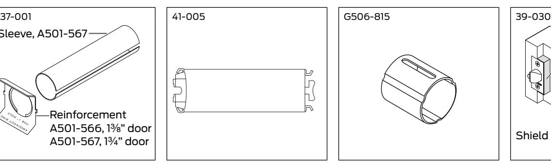
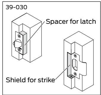
- * 39-030 Rabbeted latch and strike kit is available for Springlatch and Deadlatch applications. Available in 605 and 626 finish only.
- ** 41-005 requires: 1) reinforcement when used in hollow metal doors, and 2) one G506-815 sleeve when used with 1" latch holes.
Strikes
| Part Number | Lip Length | Description |
|---|---|---|
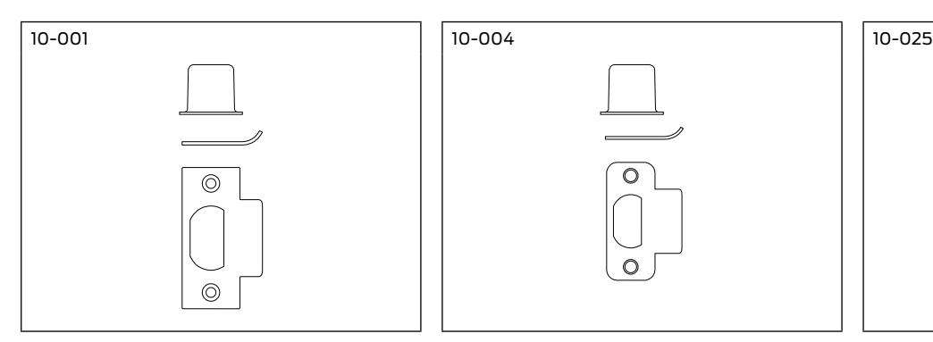
| 10-001 | 1", 1Z", 1Z\v", 1Z\x", 1C\v", 2" | Square corner T-strike 1Z" x 2C\v", with strike box (specify lip length) |
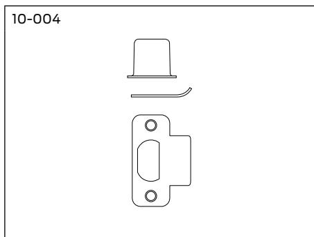
| 10-004 | 1Z" | Z\v" radius round corner T-strike 1Z" x 2C\v", with strike box |
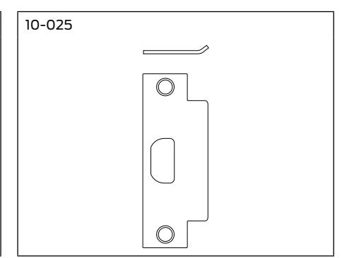
| 10-025 | 1C\zn" | ANSI 1Z\v" x 4M", standard, no box |
| 1C", 1Z\x" | ANSI 1Z\v" x 4M", no box (specify lip length) | |
| 10-026 | 1Z" | Square corner, 1B" x 2Z\v", full lip, no box |
| 10-027 | 1Z" | Z\v" radius round corner, 1B" x 2Z\v", full lip, no box |
| 10-058 | 1M\cx" | Circular, adjustable 1C\v" diameter (605 and 626 finish only) |
| K510-066 | – | Box for ANSI strike |
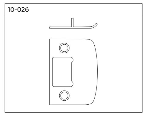
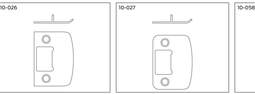
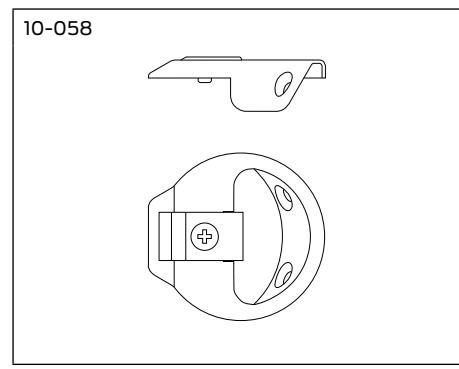
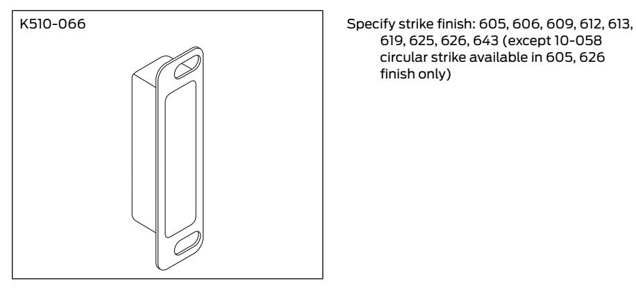
619, 625, 626, 643 (except 10-058 circular strike available in 605, 626 finish only)
Cylinder Options
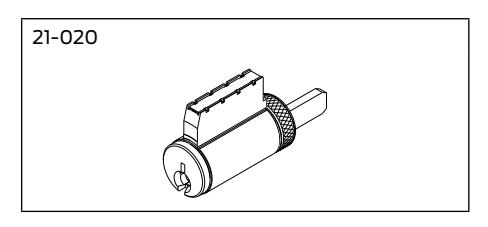
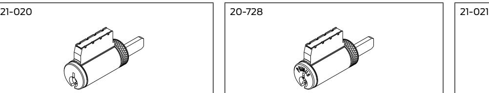
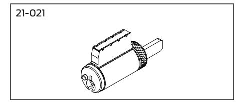
Standard Cylinders
Standard cylinders are available in Classic keyway or patented Everest keyway. Specify keyway.
| Functions | Cylinder Mechanism | Complete Cylinder |
|---|---|---|
| All functions except AL85 | Conventional | 21-020 |
| Primus | 20-728 | |
| Primus-XP | 20-728-XP | |
| Primus UL437 | 20-528 | |
| Primus UL437-XP | 20-258-XP | |
| AL85 Hotel/Motel Lock | Conventional | 21-021 |
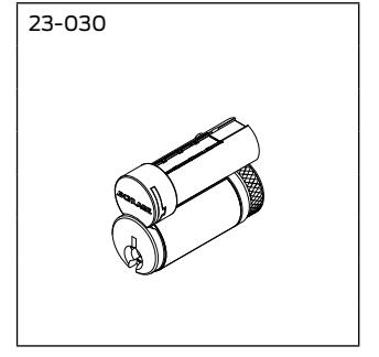
FSIC and SFIC Cylinders
Full Size Interchangeable Core (FSIC) cylinders are available for Saturn lever design and JD suffix locksets only. Locks are furnished 1-bitted with two 6-pin keys unless otherwise specified. FSIC cylinders may be integrated into any 5-pin or 6-pin Schlage key system.
Small Format Interchangeable Core (SFIC) cylinders are available for Saturn lever design and BD suffix locksets only. SFIC cylinders are for Schlage Everest B and Everest 29 R family restricted keyway cores. SFIC cylinders are compatible with Best®, Falcon and other competitive small format cores.
FSIC and SFIC cylinders are not available with Omega lever design, and not available with AL85 function .
| Description | Part Number |
|---|---|
| FSIC Conventional core | 23-030 |
| FSIC Primus | 20-740 |
| FSIC Primus-XP | 20-740-XP |
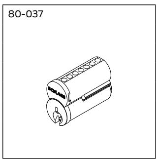
| SFIC Everest combinated core | 80-037 |
| SFIC Everest uncombinated core | 80-036 |
| SFIC Best keyway 7-pin uncombinated core | 80-033 |
| SFIC Best keyway 6-pin uncombinated core | 80-043 |
Full Size Interchangeable Core
Classic, Exploded View
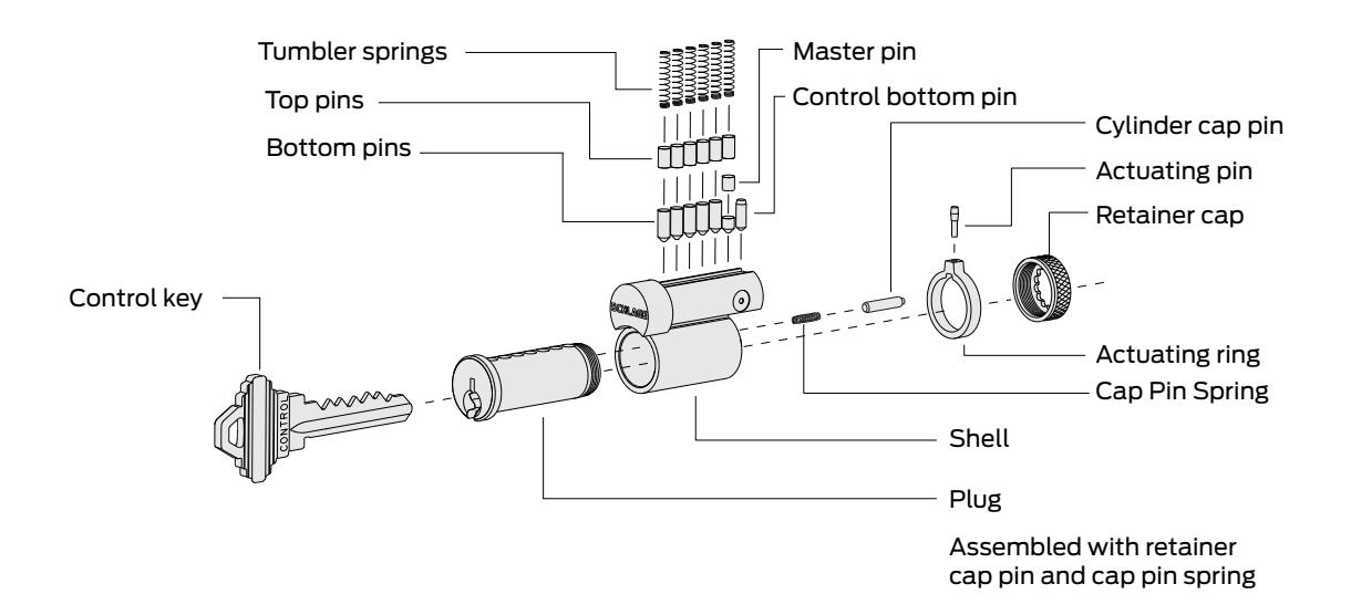
Full Size Interchangeable Core Parts
| Description | Part Number | Description | Part Number |
|---|---|---|---|
| Cap pin spring | C503-115 | Actuating ring | C603-956 |
| Retainer cap | C503-118 | Actuating pin (control top pin) | C603-964 |
| Cylinder cap pin | C603-827 | Control bottom pin | C603-967 |
| Description | Part Number |
|---|---|
| Actuating ring | C603-956 |
| Actuating pin (control top pin) | C603-964 |
| Control bottom pin | C603-967 |
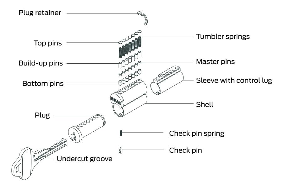
Small Format Interchangeable Core
Everest, Exploded View
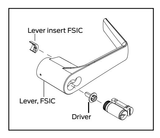
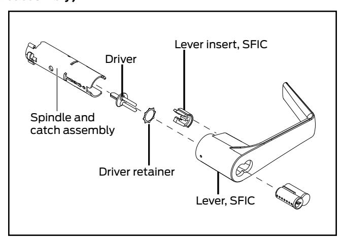
Interchangeable Core Related Parts and Levers
| Description | Part Number |
|---|---|
| Full size core lever and lever insert | 51-022 |
| Full size core driver, universal | A700-052 |
| Small format core lever and lever insert | 51-024 |
| Small format core retainer | A700-021 |
| Small format core driver | C604-381 |
| Small format core spacer | D500-000* |
| Small format core spindle and catch, outside (AL50, AL53, AL70, AL80) | A710-008 |
| Lever insert, SFIC | A700-045 |
| Lever insert, FSIC, 1C" - 1M" doors | A700-047** |
* Two spacers required for 6-pin, one spacer required for 7-pin.
Cylinder Conversion
(for part numbers, refer to list above)
Conventional Cylinder to FSIC Conventional Cylinder to SFIC (requires chassis disassembly)
** For locks manufactured after March 2003.
Parts
Parts for 2-Inch Doors
| Part Number | Description |
|---|---|
| A700-043 | Driver Bushing, 2-inch door (specify finish) |
| A700-028 | Hub, 2-inch door, outside and inside, except AL25 and AL70 outside (for locks manufactured after May 2003) * |
| A700-029 | Hub, 2-inch door, outside AL70 (for locks manufactured after May 2003) * |
| A700-030 | Hub, 2-inch door, outside AL25 |
| A700-033 | Full size interchangeable core lever insert, 2-inch door |
| A700-034 | Lever insert, 2-inch door |
* For locks manufactured before May 2003, see "Hub, Frame and Housing Kits" below.
Hub, Frame and Housing Kits
for Locks Manufactured before May, 2003
| Part Number | Function(s) | Door Thickness | Kit Contents | |||||
|---|---|---|---|---|---|---|---|---|
| A700-048 | ALL except AL25 | 1C" - 1M" | A700-046, Hub (2) | A700-057, Housing (1) | ||||
| and AL70 | A700-056, Frame, hub (1) | |||||||
| A700-050 | 2" | A700-056, Frame, hub (1) | A700-057, Housing (1) | |||||
| A700-028, Hub (2) | ||||||||
| A700-049 | AL70 | 1C" - 1M" | A700-056, Frame, hub (1) | A700-014, Hub (1) | ||||
| A700-046, Hub (1) | A700-057, Housing (1) | |||||||
| A700-051 | A700-056, Frame, hub (1) | A700-029, Hub (1) | ||||||
| A700-028, Hub (1) | A700-057, Housing (1) | |||||||
Plunger Units
| Part Number | Description |
|---|---|
| 51-037 | Plunger unit, inside, AL53 |
| 51-038 | Plunger unit, inside, AL85 |
| 51-039 | Plunger unit, inside, AL40, AL44, AL50 |
| 51-040 | Plunger unit, outside, AL40 |
| 51-041 | Plunger unit, outside, AL44 |
Specify finish.
Screws and Screw Packs
Screws
| Part Number | Description |
|---|---|
| A501-171 | Washer, thru bolt, AL170, specify finish |
| A501-746 | Mounting, thru bolt, AL170 (Z\v"-20 x 2Z\x", POH machine screw), specify finish |
| C603-256 | ANSI strike, (12-24 x 1", PFH combo screw), specify finish |
| C603-897 | Latch and strike, (8-32 x C\v", PFH combo screw), specify finish |
| C604-395 | Spring cage, (8-32 x 2Z", PFH machine screw) |
| L583-133 | Mounting, surface, AL170 (#8 x 1", sheet metal screw) |
Screw Packs, Standard
| Part Number | Description/Contents |
|---|---|
| B202-517 | Latch and strike: C603-897 (4), specify finish |
| C203-736 | ANSI strike: C603-256 (2), specify finish |
| C303-438 | Spring cage: C604-395 (2) |
| C303-029 | Mounting, all functions except AL170: C603-897 (4); C604-395 (2); C603-256 (2); M504-271 (1), specify finish |
| C303-421 | Mounting, AL170: A501-167 (1); A501-171 (1); A501-746 (1); L583-133 (2); M504-271 (1), specify finish |
Screw Packs, Torx
| Part Number | Description/Contents | |||||
|---|---|---|---|---|---|---|
| C203-311 | Latch and strike: C503-766, T-15 (4), specify finish | |||||
| C203-312 | Latch and strike: C503-766, T-15 (2); L583-371, T-20 (2), specify finish | |||||
Note: Torx screw packs are furnished with appropriate T-xx installation tool(s).
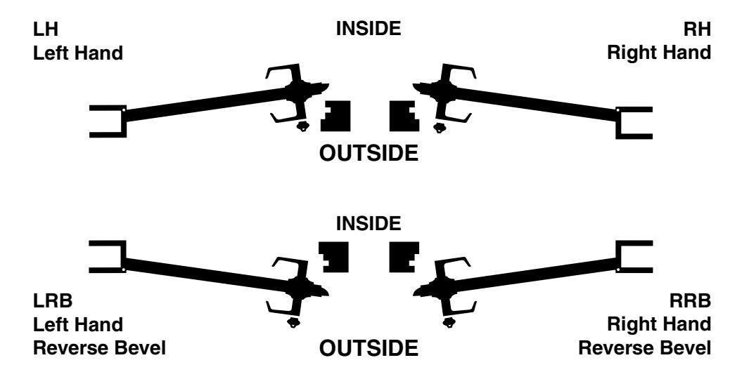
Door Handing
All Schlage locks are reversible. Hand information should be specified to ensure proper cylinder orientation in keyed functions, and to ensure proper finish of latchbolt and strike for locks to be installed on reverse bevel doors. Use the diagram below to correctly determine the hand of the door.
Ordering Procedure
To order Schlage products, descriptive data should be in the same sequence as shown below.
| Line | Qty | Product | Outside | Inside |
Hand
Latch |
Strike | Dr | Ext | Dim | Additional | |||
|---|---|---|---|---|---|---|---|---|---|---|---|---|---|
| Item | DES | FIN | DES | FIN | Thk | Details | |||||||
| 1 | 2 | 3 | 4 | 5 | 6 | 7 | 8 | 9 | 10 | 11 | 12 | 13 | 14 |
| Line Item: | Line item number |
|---|---|
| Qty: | Quantity |
| Product: | Complete lock product or part number |
| Outside DES: | Outside design code |
| Outside FIN: | Outside finish code |
| Inside DES: | Inside design code |
| Inside FIN: | Inside finish code |
| Hand: | Hand of door: Only one hand allowed per line item. Example: RH=right hand, LH=left hand, RR=right reverse, LH=left reverse |
| Latch: | Leave blank for standard latch or specify part number if non-standard latch is required |
| Strike: | Leave blank for standard strike or specify part number if non-standard latch is required. LLL=less strike |
| Dr Thk: |
Door thickness: Enter door thickness if non-standard, example 138=1C", 214=2Z\v", 212=2Z\x" (EI or EO assumes the latch will be
centered on 1" door, to which material has been added) |
| Ext: |
Extension: Enter one of the following when door 2" thick or greater are specified: EE=extended equally, EI=extended inside,
EO=extended outside, ED=extended differently |
| Dim: | Dimension: Enter dimension for non-standard strike lip length and mortise cylinder or blocking ring length |
| Additional Details: | Enter detail for keying information and for special requirements. |
Limited Warranty
Schlage Lock Company (the "Company") extends a three-year limited warranty from the original date of purchase to the Original User of the products manufactured by the Company (the "Product") against defects in material and workmanship. Certain Products contain restrictions to this limited warranty, additional warranties or different warranty periods. Please see below for specific Product warranty information.
The provisions of this warranty do not apply to Products:(i) used for purposes for which they are not designed or intended; (ii) which have been subjected to alteration, abuse, misuse, negligence or accident; (iii) which have been improperly stored, installed, maintained or operated; (iv) which have been used in violation of written instructions provided by Schlage; (v) which have been subjected to improper temperature, humidity or other environmental conditions (i.e., corrosion); or (vi) which, based on Schlage's examination, do not disclose to Schlage's satisfaction non-conformance to the warranty. Additionally, Schlage will not warrant ANSI A156.2 Grade 2 lever Product installed in educational facilities and student housing.
Specific Product Warranty Restrictions / Additional Warranties
Small Format Interchangeable Core (SFIC) Warranty: This limited warranty also applies to Schlage locks and housings when used with another manufacturer's cores, or to Schlage cores (i.e. SFIC) when used in another manufacturer's locks and housings. The use of unauthorized cylinder cams or other components with the Products shall void this warranty.
Everest® Primus® Limited Lifetime Key Breakage Warranty:A limited lifetime warranty is provided to the Original User against key breakage, subject to the restrictions of this limited warranty.
About Allegion
Allegion (NYSE: ALLE) creates peace of mind by pioneering safety and security. As a $2 billion provider of security solutions for homes and businesses, Allegion employs more than 7,800 people and sells products in more than 120 countries across the world. Allegion comprises 23 global brands, including strategic brands CISA®, Interflex®, LCN®, Schlage® and Von Duprin®.
For more, visit www.allegion.com .