Schlage AD 400 User Guide
Open the original PDF document
View PDF


P516-127
AD-400 AD-402
Networked wireless lock user guide Instructions for adaptable series networked wireless locks
Contents
| Overview3 | |
|---|---|
|
Getting started
4 |
|
| Schlage Utility Software (SUS)4 | |
| Optional inside push button (IPB)5 | |
|
User management
5 |
|
|
Construction access mode
6 Locks with keypads – Construction access mode6 Locks with card readers – Create a master construction credential 6 Locks with card readers – Add construction access mode user credentials7 |
|
|
Cancel construction access mode
7 |
|
|
Link to a PIM4008
Link LED and beep reference 8 |
|
|
Test lock operation9
Mechanical test 9 Electronic test9 |
|
|
Reset to factory default settings
10 Level 1 factory default reset10 Level 2 factory default reset10 |
|
| Communication properties | 11 |
| Communication failure | 11 |
|
Batteries12
Installing or replacing batteries 12 Low battery indications12 Battery failure modes 13 |
|
|
External power supply
13 |
|
| LED and beep reference13 | |
|
Troubleshooting
14 |
|
|
FCC/IC statements
15 |
To comply with FCC and Industry Canada RF radiation exposure limits for general population, the antenna(s) used for this transmitter must be installed such that a minimum separation distance of 20 cm is maintained between the radiator (antenna) and all persons at all times and must not be co-located or operating in conjunction with any other antenna or transmitter.
This product is compliant of UL294 and ULCS319 standard. This product's compliance would be invalidated through the use of any add-on, expansion, memory or other module that has not yet been evaluated for compatibility for use with this UL Listed product, in accordance with the requirements of the Standards UL294 and ULCS319. This product has been evaluated for ULC-S319 Class I.
UL294 Access Control Levels tested to: Destructive Attack - Level 1; Line Security - Level 1; Endurance - Level 4; Standby Power - Level 1.
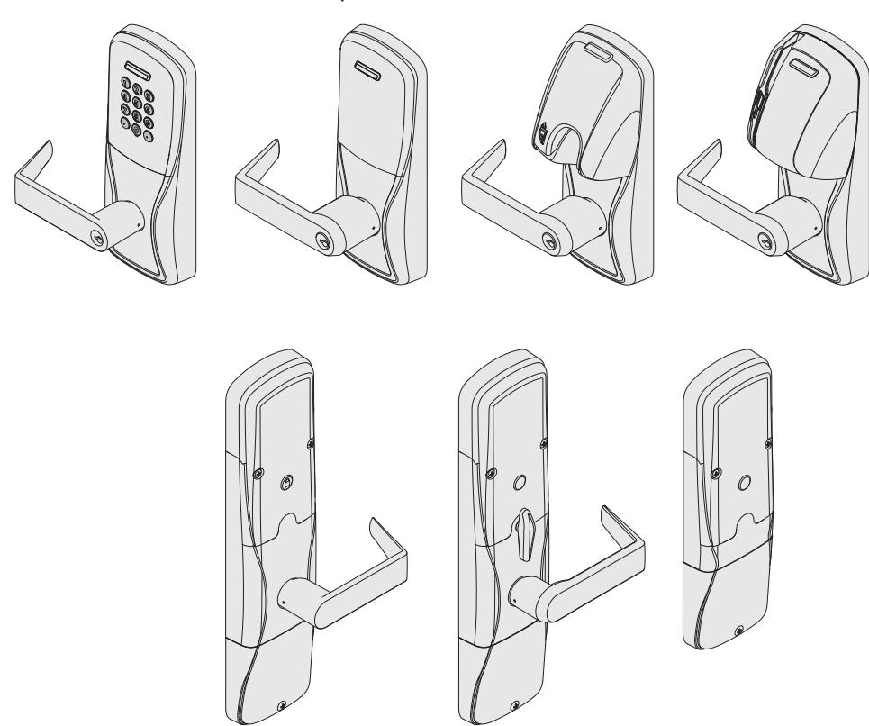
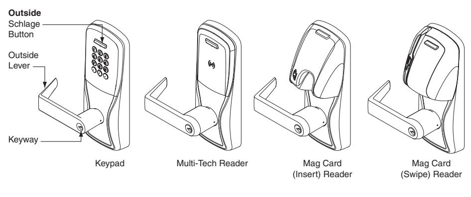
Overview
The Schlage AD-400 is an open architecture Wireless Access Point Module (WAPM) designed to interface with third-party panels through a PIM400.
The Schlage AD-402 is a certified Wireless Access Point Module (WAPM).
- The AD-400/AD-402 communicates with the PIM400 via RF (radio frequency).
- The AD-400/AD-402 may be battery powered or connected to external power using a UL294 or ULCS318/ULCS319 listed power supply. See Batteries on page 12 or External power supply on page 13 for more information.
- The outside lever is normally locked.
- The inside lever always allows egress.
- The AD-400/AD-402 normally operates in on-line mode. Information contained in the user credential is passed to an access control panel (ACP), which controls lock functions. The ACP maintains the audit trail.
Additional AD-400 Reader options: Mag + Keypad, Multi-Tech + Keypad.
Note: Proximity card (PR, PRK) ONLY and Smart card (SM, SMK) ONLY reader have been discontinued and replaced by the Multi-Tech (MT, MTK) readers that provide all the same funcionality as the original Proximity and Smart card readers in a single credential reader.
The AD-402 reader is a FIPS-201-2 certified Multi-Tech + Keypad (FM2) reader.
Getting started
Follow these steps when setting up a new lock.
- 1. Install the lock. See the installation guide that came with the lock or visit www.allegion.com/us for more information.
- 2. Make sure the batteries are installed properly. See Batteries on page 12 for more information.
- 3. Configure the Master Construction Credential (where applicable). See Construction access mode on page 6 for more information. The lock should remain in Construction Access Mode until you are ready to set up the rest of the wireless access system with connection to the PIM400 and the access control panel (ACP).
- 4. Link the lock to the PIM400. See Link to a PIM400 on page 8 for more information.
- 5. Test the lock for proper mechanical and electronic operation. See Test lock operation on page 9 for more information.
- 6. Consult the SUS User Guide for information about configuring the lock and PIM400.
- 7. Familiarize yourself with the information contained in this user guide.
Save this user guide for future reference.
Schlage Utility Software (SUS)
The SUS is used to configure locks and the PIM400.
L When in a low battery condition the lock may operate but not have sufficient power to communicate with the SUS. When intitiating SUS communication, the Schlage button will light solid red for one second to indicate power is not sufficient. If this should occur, change the batteries immediately. See Batteries on page 12.
The SUS is used for programming lock characteristics and setup only. Access rights for the AD-400/AD-402 are set by the access control panel, not by the SUS.
For more information about the SUS, see AD-Series Locks in the SUS User Guide.
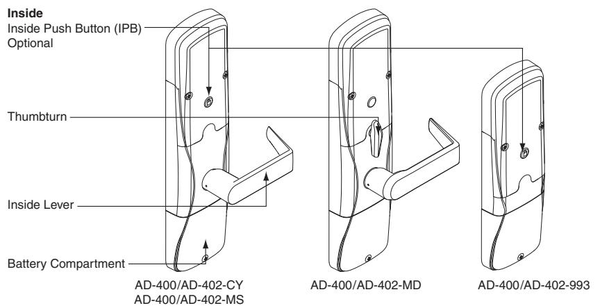
Optional inside push button (IPB)
- The inside push button (IPB) state is communicated to the access control panel by the PIM400-485. The manner in which the network access control software utilizes this communication is configured at the host. The IPB may be used to communicate a lock/ unlock request or be completely ignored by the network software.
- AD-400 IPB activity will only be reported to control systems connected to a PIM400-485 with a RS-485 connection.
- The IPB may be configured by the ACP or SUS to take direct action on the lock state in case communication from the control system to the AD-400 fails and the lock remains powered.
User management
User management is controlled by the access control system. If the access control panel has not yet been connected, use Construction Access Mode to add and delete users.
L See Construction access mode on page 6 for more information.
For compliance with the UL Standards UL294 and ULCS319, the AD-400/AD-402 must be connected to an access control panel (ACP) that is UL listed for UL294 for UL installations and ULCS319 for cUL installations.
Construction access mode
Construction access mode is used to allow access before the lock has been programmed, and for testing purposes.
- Enabled by default.
- The lock will remain in construction access mode until the mode is cancelled as described below.
- No audits are captured while lock is in construction access mode.
- Use the same master construction credential for all the locks in the facility.
- If you present the first card to a new lock to create the master construction credential and the card is not accepted, the lock has either been programmed or already has a master construction credential.
- If the master construction credential cannot be located, or to put the lock back into construction access mode, reset the lock to factory settings (see page 10 for details).
Locks with keypads – Construction access mode
In the factory default state, locks with keypads have a default PIN of 13579 and "#", which can be used for installation, testing and construction access. To test, enter default PIN. The Schlage button will blink and the lock will unlock.
The default PIN, 13579 and "#" is automatically deleted when a construction access user credential is added to the lock, or a new programming credential is created, or the lock is programmed with the SUS.
Locks with card readers – Create a master construction credential
The master construction credential is used to program construction access mode credentials.
To create a master construction credential:
- 1. Press and hold the Schlage button while presenting a credential.
- 2. The Schlage button will blink green on the left and right as confirmation.
- 3. Use this card to add construction access mode user credentials.
- L The master construction credential will not grant access. It is used only to add additional credentials.
Locks with card readers – Add construction access mode user credentials
|
Construction
access mode credential type |
Steps to add construction access mode user credentials | ||||
|---|---|---|---|---|---|
| 1 | 2 | 3 | 4 | 5 | |
|
Normal use
construction credential Unlocks the lock for relock delay period |
Present
master construction credential to reader |
Green LEDs
blink |
Present user
credential within 20 seconds |
Green LEDs
blink and credential is added |
Repeat steps
3 and 4 for additional credentials. |
|
Toggle
construction credential Changes the state of the lock from locked to unlocked or vice versa |
Present
master construction credential to reader |
Green LEDs
blink |
Press and
hold Schlage button while presenting user credential within 20 seconds |
Green LEDs
blink 5 times, 2 beeps will sound and credential is added |
Credentials
added with the master construction credential will have 24/7 access. |
Cancel construction access mode
Do one of the following:
- Program the lock with the SUS. See the SUS user guide for more information.
- Reset the lock to factory settings. See Reset to factory default settings on page 10 for more information.
When construction mode is cancelled, the master construction credential and all other credentials added using the master construction credential will no longer function.
Link to a PIM400
-
L
Only one AD-400/AD-402 can be linked at one time. Ensure that no other PIM400 units are in link mode during this process.
- 1. Make sure the batteries are installed in the AD-400/ AD-402. See Batteries on page 12 for more information.
- 2. Make sure the PIM400 is in link mode. For PIM400-TD2: Hold down one of the LINK buttons. (LINK button 1 or 2 will assign the lock door number). For PIM400-485: Use SUS to put the PIM400-485 into LINK mode with the door number tab and assign the lock door number. See the SUS User Guide for more information.
- 3. Open the AD-400/AD-402 door.
- 4. Create a request-to-exit condition by holding down the inside lever or crash bar.
TIP
During linking, the Schlage button will blink red and green. Green blinks indicate successful packets and red blinks indicate unsuccessful packets. If you get several red blinks, the lock and PIM400 may still link, but you may experience intermittent communication in the future. You should move the PIM400 closer to the lock, select another RF channel or add another PIM400.
- L If using a crash bar, Request to Exit (RTX) must be installed. If RTX is not installed, temporarily short the RTX input on the lock main PCB during this procedure.
- 5. While holding down the lever or crash bar, present a card to the prox or mag card reader. For a keypad reader, press the "#" key.
- 6. Continue to hold down the lever or crash bar until the AD-400/AD-402 Schlage button starts to blink green, indicating that the link process has begun (approximately 8 seconds).
- 7. Release the inside lever or crash bar.
- 8. The Schlage button will blink green, and the beeper will beep.
-
L
The number of green blinks and beeps indicates the frequency channel number on which the lock is linked to the PIM400 (example: 3 blinks and beeps = channel 3).
- 9. If the link fails, the Schlage button will blink red three (3) times and five (5) short beeps will sound. The PIM400 will remain in link mode. Carefully repeat steps 1-8 above. If repeated LINK attempts fail, change the frequency channel of the PIM400 and/or move the PIM400, then repeat steps 3-7.
- 10. Test the lock for normal operation. See Test lock operation on page 9 for more information.
Re-linking is required anytime the AD-400/AD-402 lock or the PIM400 is moved or replaced, Dynamic Channel Switching is activated, deactivated, or the frequency channel is manually changed.To re-link, repeat the procedure above. The lock's link to the PIM400 is retained in the event of power loss.
Link LED and beep reference
| Lights | Beeps | Action |
|---|---|---|
| 1 Red, | 0 | One link request was sent to find a PIM400 in link mode. This will |
| 1 Green | repeat once and then the lock will stop trying to find a PIM400. | |
| 1 Green | 0 | Successful RF packet transmission |
| 1 Red | 0 | Unsuccessful RF packet transmission |
| Z Green1 | Z1 | Linking was successful1 |
| 3 Red | 5 | Linking was unsuccessful |
Z = Frequency channel number on which the lock is linked (1-10). The frequency channel number of each PIM400 in the area should be known and recorded. Use this information to make sure the AD-400/AD-402 lock is linked to the intended PIM400.
Test lock operation
If you encounter problems while performing any of the following tests, review the installation instructions and this guide and correct any problems.
Mechanical test
- 1. Rotate the inside lever. Operation should be smooth, and the latch should retract.
- 2. Insert the key into the keyway and rotate the key, or the key and lever to open the door. Operation should be smooth, and the latch should retract.
Electronic test
Test the AD-400/AD-402 in factory default mode
- 1. For locks with a keypad, press any number key. The lock should beep.
- 2. Press the Schlage button. The keypad should light blue for a few seconds.
- 3. For locks with a card reader, present a credential to the reader. The lock will beep and the Schlage button will blink red one time. When the lock is in factory default mode, no credentials are accepted and the lock will respond with one red blink indicating the lock is not linked with the PIM400.
- 4. Locks with keypads, with or without additional credentials, have a default PIN of 13579 and " # ". To test, enter the default PIN. The Schlage button will blink and the lock will unlock.
Test the AD-400/AD-402 in construction access mode
- 1. When the master construction credential is presented, the AD-400/AD-402 will beep and the Schlage button will light green for 20 seconds awaiting the presentation of another credential to be granted construction user access.
- 2. When a valid construction access user credential is presented, the lock will unlock for the re-latch delay period (default three seconds), and the Schlage button will blink green. When the lock re-locks after the re-latch delay period, the Schlage button will blink red.
- 3. If an invalid construction access user credential is presented, the lock will beep and the Schlage button will blink red one time. See Construction access mode on page 6 for more information.
NOTE: Construction access mode is cancelled when the lock is either linked to a PIM400, or reset to factory defaults. When construction access mode is cancelled, the master construction credential and all other credentials added using the master construction credential will no longer function.
Test with the AD-400/AD-402 linked to the PIM400 and Access Control Panel
Once the AD-400/AD-402 is linked to the PIM400, the SUS will indicate a successful link. The SUS will display AD-400/AD-402 operations and communication status with the PIM400.
- 1. In the SUS "demo/diagnostics" menu display for the PIM400, choose "Select door" and set a door number for the lock being tested. The SUS will display operation and status for link, reader data, motor, tamper, battery, request-to-enter, request-to-exit and door position switch.
-
L
If the SUS demo/diagnostics "UNLOCK ON READ" box is checked, all credentials will unlock the AD-400/AD-402 during demo/diagnostics check.
- 2. Present a valid credential to the AD-400/AD-402. The Schlage button will blink green, a beep will sound and the door will unlock for the preset lock delay period. The lock will re-lock after the lock delay period and the Schlage button will then blink red.
- 3. If an invalid credential is presented, the Schlage button will blink red, a beep will sound and the door will not unlock. Credential data for all credentials is reported to the PIM400 and displayed at the ACP.
Reset to factory default settings
L All information in the lock will be deleted and reset to factory defaults!
Level 1 factory default reset
- L Level 1 factory default reset will delete configurations and settings in the main controller in the lock.
-
L
Level 1 factory default reset will not reset configurations and settings in the reader.
- 1. Remove the top inside cover.
- 2. Press and hold the Schlage button until two (2) beeps sound (10 seconds).
- 3. Release the Schlage button.
- 4. Press and release the inside push button (IPB) three (3) times within 10 seconds. One beep will sound and one red blink will occur with each press.
- 5. The Schlage button and IPB will both light green for one second and a one-second beep will sound to confirm that the lock has been reset.
- L If IPB is not pressed 3 times within 10 seconds, two beeps with two red blinks indicate timeout.
- 6. Replace the top inside cover.
Level 2 factory default reset
- L Level 2 factory default reset will delete all configurations and settings in the lock and the reader.
- L Reader configurations that will reset to factory default include: keypad format, magstripe reader track, beeper on/off, and contactless card.
- L Days in use counter and lock type configurations will not reset.
To complete Level 2 factory default reset, repeat steps 2 through 5 above within 10 seconds of the confirmation signals of Level 1 factory default reset . If more than 10 seconds pass after the confirmation signals of Level 1 reset, then Level 1 reset will be repeated.
Communication properties
| Property | Description |
|---|---|
| Heartbeat |
When the lock is idle, the heartbeat is a brief communication from the lock
to the PIM400. |
|
The heartbeat allows an idle lock to check for messages from the PIM400. By
default, this occurs every 10 minutes, but can be adjusted in the range of 15 seconds to many hours. Short heartbeat intervals are suggested only if "Time Zones" accuracy of less than 10 minutes is desired. |
|
|
The value indicates the time between the heartbeats. Set the value to a shorter
time (lower number) to achieve more frequent communication while the lock is idle. Set the value to a longer time (higher number) to achieve less frequent communication. |
|
| Immediate |
A smaller value will decrease battery life. A larger value will increase battery life.
When the lock is used, there is immediate communication to and from the PIM400 regardless of the heartbeat interval. |
|
Wake-Up
On Radio |
When enabled, this feature causes the lock to respond within seconds to a
centralized command from the access control panel. When disabled, the lock will respond only during its heartbeat, which could result in a delay. |
|
Test the function of Wake-Up On Radio, both lock and unlock operations, after
all locks are installed. To test, verify that all locks go to the requested state with no assistance or intervention. If test fails, toggle Dynamic Channel Switching (DCS) to its opposite state (off to on, or on to off). Then, re-link all locks and test again. |
|
|
Cache
Mode |
When enabled and communicating with the ACP, the lock keeps a local
database of successful access grants. |
|
(not
applicable on AD-402 |
In the event of communication failure between the AD-400 lock and the
PIM400, or between the PIM400 and the ACP, access is enabled for facility codes or recent valid users full card numbers. |
| locks) |
Note: When cache mode is configured for Smart cards, the default of "full card
numbers" must be used. |
|
The local lock database does not capture audit events. See the SUS User
Guide for more information. |
Communication failure
When communication fails between the AD-400/AD-402 and the PIM400, the lock will go into communication failure mode. If the ACP or the PIM400 lose power, the lock can lock, unlock, remain as-is, or allow valid access without communicating to the ACP or the PIM400. This mode can be configured using the SUS. See the SUS user guide for more information.
| Mode | Description |
|---|---|
| Fail unsecure | Lock unlocks and remains unlocked until communication is restored. |
| unlocked | |
| Fail secure locked | Lock locks and remains locked until communication is restored. |
| Fail as-is | Lock remains in current state until communication is restored. |
In addition, the AD-400 has an internal cache, that can be enabled using the SUS, to allow limited access while the lock is offline. If cache mode is enabled, it is not affected by the communication failure mode configuration. See the SUS User Guide for more information.
Batteries
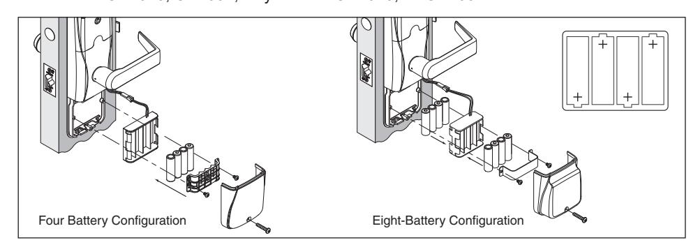
Installing or replacing batteries
Approximately one month prior to the end of the battery life, a Low Battery Trouble signal is indicated at the PIM400 and a Trouble signal will be sent to the access control panel.
- 1. Remove the battery cover.
- 2. Remove the battery bracket. Do not allow the battery pack to hang from the wires .
- 3. Install the new batteries (install only new AA Alkaline batteries). Make sure the batteries are installed in the correct orientation.
- 4. Reinstall the battery pack and battery bracket.
- 5. Reinstall the battery cover, making sure the connector is above the battery pack.
CAUTION! Danger of explosion if battery is incorrectly replaced! Replace only with the same or equivalent type. Dispose of used batteries according to the manufacturer's instructions.
This product has been evaluated for ULC-S319 compliance with AA and coin cell batteries listed below. For installations requiring ULC-S319, these battery models should be used.
AA batteries: Duracell PC1500, MN1500; Energizer E91, EN91, AX91, XR91; RayoVac 815, 815-HE
Coin cell batteries: Energizer CR2025, CR2032; Maxell CR2025, CR2032, Panasonic CR2025, CR2032; RayoVac KECR2025, KECR2032
Low battery indications
- L Replacement of batteries does not affect any programmed data. Battery voltage can be checked with the SUS.
- L When in a low battery condition the lock may operate but not have sufficient power to communicate with the SUS. When intitiating SUS communication, the Schlage button will light solid red for one second to indicate power is not sufficient. If this should occur, change the batteries immediately.
| Condition | Indicator | Solution |
|---|---|---|
| Low battery | No beeps | Replace batteries immediately to avoid |
|
Low battery condition is reported
to the Access Control Panel. |
failure. | |
| Battery failure | No LED or beeps | Replace batteries immediately. |
|
(configured
by SUS) |
Valid credentials do not grant
access |
Mechanical override key must be used
to unlock the lock. |
Battery failure modes
L The battery failure mode is set using the SUS. See the SUS user guide for more information.
| Mode | Description |
|---|---|
| Fail As-Is (default) | Lock remains in current state until batteries are replaced. |
| Fail Unlocked1 | Lock unlocks and remains unlocked until batteries are replaced. |
| Fail Locked1 | Lock locks and remains locked until batteries are replaced. |
1 Fail Unlocked and Fail Locked modes are not available if lock is externally powered.
External power supply
The AD-400/AD-402 may be connected to external power using a UL294 listed power supply for UL installations, and a power supply that complies with CAN/UL-S318 or CAN/ULC-S319 for cUL installations. The power supply must be capable of sourcing at least 250mA @ 12 or 24 VDC (Schlage PS902, PS904, PS906).
DO NOT connect both external power and AA batteries at the same time.
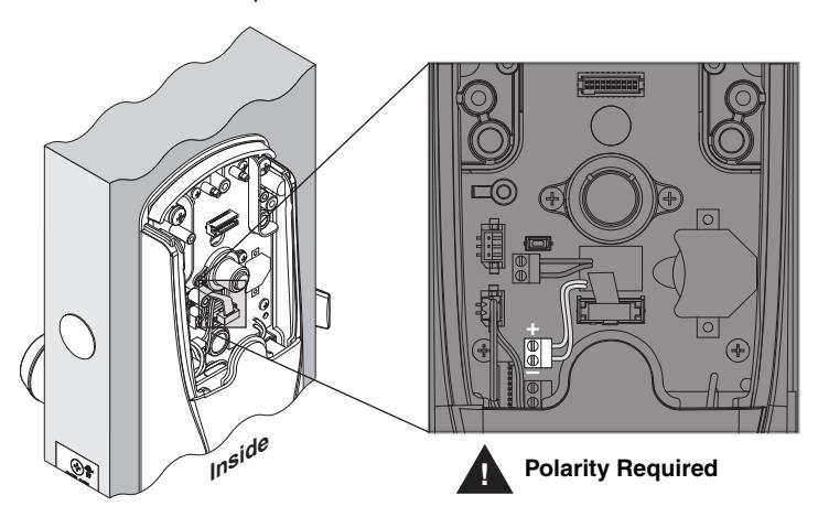
When externally powered, the lock will always fail as-is if power is lost.
LED and beep reference
The beep indicator may be enabled or disabled using the SUS. See the SUS User Guide for more information.
| Action | Schlage button LEDs | Beeps |
|---|---|---|
| Extended (Toggle) unlock | 2 green | 0 |
| Card presented and not read | None | 0 |
| Card presented and read | None | 1 |
| No communication with PIM400 or the ACP when | 1 red | 0 |
| card presented | ||
| Access denied | Controlled by ACP via PIM400 | |
| Access granted, momentary unlock (motor runs) | 1 green | 0 |
| Relock (motor runs) | 1 red | 0 |
Troubleshooting
| Possible cause | Solution | |
|---|---|---|
|
Problem
The lock beeper does not sound and the keypad does not light when the Schlage button is pressed. |
The reader may not be
properly seated into the front escutcheon. The reader connector may have bent pins. |
Check that the reader is fully seated
into the front escutcheon. Check that there are no bent pins in the reader connector. Check that the through door ribbon |
|
The through door ribbon
cable may not be properly plugged in. |
cable is plugged in correctly. The red
wire should be on the left and not pinched in the door. |
|
|
The battery or wired
power may be improperly connected. |
Check that the battery or wired power
is connected correctly. Check that the batteries are inserted in |
|
|
The batteries may be
inserted with incorrect |
the correct polarity.
Refer to the installation instructions |
|
| polarity. |
that came with the lock, or this
user guide for details on the above mentioned procedures. |
|
|
The AD-400/AD-402
will not link to the PIM400: |
The lock and the PIM400
are not linked. The PIM400 is not in |
Repeat the link procedure, making
sure the PIM400 is in link mode before beginning the link procedure with the lock. |
|
When a valid
credential is presented, the Schlage button blinks red one time OR PIM400 SUS Diagnostics shows the door status as not linked. |
link mode before the link
procedure. An incorrect door number was selected when linking the AD-400/AD-402. The Wireless Communication Module is not properly installed. |
Check that you selected the correct
door number when linking the lock, and repeat the link procedure. |
|
Check that the Wireless
Communication Module is installed and fully seated, and that there are no bent pins on the connector. |
||
|
The AD-400/AD-402 is
located too far away from the PIM400. |
The AD-400/AD-402 lock and PIM400
must be within 200 feet of each other, and on the same floor. The distance may be increased by using a remote |
|
|
Data transmission to the
access control panel is not successful even though green blinks are observed when linking to the PIM400. |
antenna or another PIM400 located
closer to the lock. |
|
|
Check that the PIM400 is wired to the
access control panel (ACP). |
||
|
Check that the ACP software has
the AD-400/AD-402 door configured properly. |
||
|
On a 993 exit trim, make sure the
Request To Exit switch is installed. |
||
|
Refer to the lock installation
instructions, and/or this user guide for details on the above mentioned procedures. |
| Problem | Possible cause | Solution |
|---|---|---|
|
The reader is not
working. |
The through hole ribbon
cable may be pinched. |
Check that the through hole ribbon
cable is not pinched. |
|
The Smart card is not
reading. The magnetic swipe |
The Smart card default of
the card reader may not be correct for the Smart card. The "Mag Track in Use" default for all Magnetic Card Credential Readers is "Track2". The magnetic swipe card data may be on Track1 or Track3. |
Change the Smart card format using
the SUS. Select AD-400/AD402 "Lock Properties", "Reader" tab, and "Smart cards in use". |
|
card is not reading
correctly (no beeps or blinks). |
Use the SUS to change "Mag Track
in Use". Select AD-400/AD402 "Lock Properties", "Reader" tab, and "MAG Card Track selection". |
|
|
Refer to the installation instructions
that came with the lock, or the SUS user guide for details on the above mentioned procedures. |
FCC/IC statements
The communication module is a 900 MHz transceiver for electronic locks and non-lock devices. The communication module links the access device to the Access Control Management System, with feedback control to the Access Device via a wireless means. The module contains the embedded fi rmware implementing the radio physical and data layers. There are 5 antennas approved for use with this module:
Approved antenna list:
The required antenna impedance is 50 ohms.
- 1. PCB trace antenna with a 5.7dBi maximum gain
- 2. p/n: 23520587, dual beam antenna with a 3.5dBi gain (ANT400-REM-HALL)
- 3. p/n: 23530579, multi band directional panel antenna with 8.5dBi gain (ANT400-REM-I/O+dB)
- 4. p/n: 23530553, dual band quasi-omni panel antenna with 4.5dBi gain (ANT400-REM-I/O)
- 5. p/n: 23520561, multi band omni antenna with 2dBi gain (ANT400-REM-CEILING)
Antennas having a gain greater than the antenna type approved in the list are strictly prohibited for use with this device. However, antennas of the same type with a gain equal to or less may be used. Examples of this may include:
- a directional panel antenna with a gain equal to or less than 8.5 dBi may be used with this module
- an omni-directional antenna with a gain equal to or less than 2.0 dBi may be used with this module
Specifications of the radio module:
Power output: 18.6 dBm Modulation: BPSK-40 Operating frequency: 906 -924 MHz
Note: The intended use of this module is not for the general public. It is generally for industry/commercial use only. This transceiver is to be professionally installed in the end product by Allegion, and not by a third party. The Schlage XPB-COMAD400V2 900 MHz Communication Board Module will not be sold to third parties via retail, general public or mail order. In the case of a repair, the transceiver will be replaced by a professional Installer.
Federal Communication Commission interference statement
This equipment has been tested and found to comply with the limits for a Class B digital device, pursuant to Part 15 of the FCC Rules. These limits are designed to provide reasonable protection against harmful interference in a residential installation. This equipment generates uses and can radiate radio frequency energy and, if not installed and used in accordance with the instructions, may cause harmful interference to radio communication. However, there is no guarantee that interference will not occur in a particular installation. If this equipment does cause harmful interference to radio or television reception, which can be determined by turning the equipment off and on, the user is encouraged to try to correct the interference by one of the following measures:
- Reorient or relocate the receiving antenna.
- Increase the separation between the equipment and receiver.
- Connect the equipment into an outlet on a circuit different from that to which the receiver is connected.
- Consult the dealer or an experienced radio/TV technician for help.
This device complies with Part 15 of the FCC Rules.
Operation is subject to the following two conditions: (1) This device may not cause harmful interference, and (2) this device must accept any interference received, including interference that may cause undesired operation.
FCC/IC caution
Any changes or modifications not expressly approved by the party responsible for compliance could void the user's authority to operate this equipment.
To comply with FCC/IC RF exposure limits for general population/uncontrolled exposure, the antenna(s) used for this transmitter must be installed to provide a separation distance of at least 20 cm from all persons and must not be co-located or operating in conjunction with any other antenna or transmitter.
Industry Canada statements
This Device complies with Industry Canada License-exempt RSS standard(s). Operation is subject to the following two conditions:
- (1) this device may not cause interference, and
- (2) this device must accept any interference, including interference that may cause undesired operation of the device.
Under Industry Canada regulations, this radio transmitter may only operate using an antenna of a type and maximum (or lesser) gain approved for the transmitter by Industry Canada. To reduce potential radio interference to other users, the antenna type and its gain should be so chosen that the equivalent isotropically radiated power (e.i.r.p.) is not more than that permitted for successful communication.
This radio transmitter, 8053B-COMAD400V2, has been approved by Industry Canada to operate with the antenna types listed below with the maximum permissible gain and required antenna impedance for each antenna type indicated.
Approved antenna list:
The required antenna impedance is 50 ohms.
- 1. PCB trace antenna with a 5.7dBi maximum gain
- 2. p/n: 23520587, Dual Beam Antenna with a 3.5dBi gain (ANT400-REM-HALL)
- 3. p/n: 23530579, Multi band Directional Panel antenna with 8.5dBi gain (ANT400-REM-I/O+dB)
- 4. p/n: 23530553, Dual Band Quasi-Omni Panel Antenna with 4.5dBi gain (ANT400-REM-I/O)
- 5. p/n: 23520561, Multi band Omni Antenna with 2dBi gain (ANT400-REM-CEILING)
Antennas having a gain greater than the antenna type approved in the list are strictly prohibited for use with this device. However, antennas of the same type with a gain equal to or less may be used. Examples of this may include:
- a directional panel antenna with a gain equal to or less than 8.5 dBi may be used with this module
- an omni-directional antenna with a gain equal to or less than 2.0 dBi may be used with this module.
To comply with IC RF exposure limits for general population/uncontrolled exposure, the antenna(s) used for this transmitter must be installed to provide a separation distance of at least 20 cm from all persons and must not be collocated or operating in conjunction with any other antenna or transmitter.