Sargent & Greenleaf Titan Direct Drive Electronic Safe Lock
Open the original PDF document
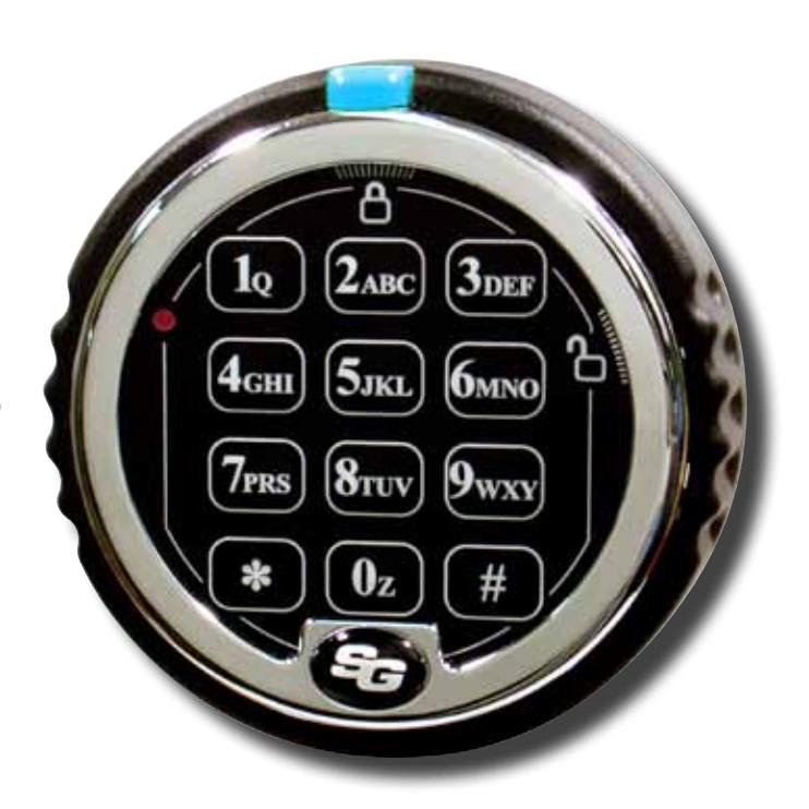
View PDFS&G<sup>®</sup> Titan<sup>™</sup> Direct Drive Electronic Safe Lock
Advanced Design Direct Drive Electronic Safe Lock
Why S&G® Titan™?
- Completely redesigned locking mechanism based on the proven security of a rugged, motorized blocking device.
- Lock bolt retraction and extension is controlled directly by turning the keypad ring.
- Attach boltwork or a blocking bar directly to the lock bolt or to optional locking bars without fear of overwhelming the lock's drive mechanism or accelerating wear.
The Titan™ Direct Drive Advantage:
- An exclusive, no-twist cable design that virtually eliminates the risk of cable damage due to keypad rotation.
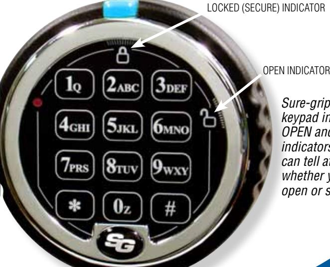
- Sure-grip, low profile keypad gives a good, solid feel for the action of the lock.
- Underwriters Laboratories Type 1 Listing and several additional international agency ratings.


- Low profile keypad incorporates an open/close indicator to let you know at a glance if the safe is locked or unlocked.
- External battery placement puts the battery inside the keypad, where it can be easily changed. And efficient lock design means the battery must be changed significantly less often.
- Field installable bolt position indicator (BPI) module is available to let you tie lock action to alarms, video surveillance recorders, etc. The module can be added to a lock at any time, with minimal labor.
- Program the lock from the keypad at any time.
- The S&G<sup>®</sup> Titan™ lock body is the same size and mounting footprint as other standard S&G locks. allowing for easy retrofit without the need for boltwork or mounting screw location changes. Plus, it's universally handed for RH, LH, VU, and VD mounting.
STANLEY, STANLEY in a notched rectangle, SARGENT AND GREENLEAF, S&G, and TITAN are some of the trademarks of The Stanley Works or its affiliates. UL and UL in a circle are trademarks of Underwriters Laboratories.

Titan™ D-Drive by Sargent and Greenleaf
Advanced electronic technology and positive bolt control
Choose Your Optimum Mode through the Keypad
The Titan™ D-Drive lock is rated by several international security agencies and is UL Type 1 Listed. In addition, it's RoHS compliant.


- Multi-User—The Master Code, Supervisor Code, and any User Code can open the lock with a single code.
- Manager/Employee—Code holders can access the safe only when it's been enabled by a Master Code or Supervisor Code holder.
- Dual Control—Multi-User mode is the factory default, but Dual Control is keypad selectable as an alternate, permanent mode of operation. Two different lock codes must be entered within one minute of each other to open the safe. This provides a higher level of security.
Multiple Codes —
• One Master Code, one Supervisor Code, eight User Codes*, one Time Delay Override Code, and a Management Reset Code.
Holdup Protection —
• Time delay is a proven holdup deterrent. The S&G® Titan™ D-Drive lock gives you a time delay up to 99 minutes, and a time delay override code for instant cash carrier access.
* When a time delay override code is set, the number of available user codes is seven. If the lock is set to multiple user mode and duress is turned on, only User Codes 2 and 3 are available. User Codes 4 – 8 are disabled. User Code 9 will be available to use if time delay override is not enabled. Loss of User Codes when duress is enabled is required to meet EN1300 specifications for this product. If the lock is set to dual user mode, all codes always remain available.
Protect your assets with the Titan™
Optional Bolt Position Indicator (BPI) module can trigger alarms, CCTV recorders, or virtually any relay activated security device.
The lock cable is completely protected in a specially designed channel in the spindle. It can't get caught, pinched, or crimped as the lock is operated day after day.
The lock battery is housed in a special compartment inside the keypad, where it can be easily accessed for changing.
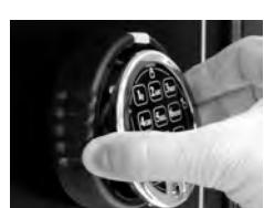
Sure-grip, low profile keypad incorporates OPEN and CLOSE indicators. You can tell at a glance whether your lock is open or secure.
D-Drive electronic safe lock.
www.sargentandgreenleaf.com
Corporate Headquarters: One Security Drive • Nicholasville, Kentucky 40356 • USA • Tel. 859-885-9411, Fax 859-887-2057 European Headquarters: 9, chemin du Croset • 1024 Ecublens• Switzerland • Tel. 41 21 694 34 00, Fax 41 21 694 34 09


Multiple-User Mode Operating Guide for Lock Models 2006 and 2007
Change from Multiple-User to Dual-User—This non-reversible function change must be done before the factory Master Code is changed for the first time. You will need to use the Dual-User Operating Guide after function change.
7 6 * 1 2 3 4 5 6 # ( ) 1 # ( ) 1 # ( )
Note: User 2 will be automatically installed as code 2 2 2 2 2 2, and the Management Reset Code will become inoperable to prevent dual control from being overridden.
Reset the Lock's Factory Programmed Management Reset Code (MRC) to a Code of Your Own Choosing
6 7 * 1 2 3 4 5 6 # ( ) NEW 8-DIGIT MRC # ( ) NEW 8-DIGIT MRC # ( )
Note: The MRC can only be changed at the keypad by using the factory default master code of 1 2 3 4 5 6 before the master code is changed for the first time.
Delete the Lock's Management Reset Code (MRC)
6 7 * 1 2 3 4 5 6 # ( ) # ( ) # ( )
Note: The MRC can only be deleted at the keypad by using the factory default master code of 1 2 3 4 5 6 before the master code is changed for the first time.
Opening the Lock using the Factory Default Code
The factory default Master Code is 1 2 3 4 5 6. To open the lock, enter 1 2 3 4 5 6 # then rotate the keypad to the right if D•Drive or turn safe handle if any other model of lock is installed .
Disable the Time Delay Override Function
8 3 * 1 2 3 4 5 6 # ( ) 1 # ( ) 1 # ( )
Notes: This programming sequence MUST be performed before the Master Code is changed for the first time.
Changing Your Own Code or the Factory Default Code
2 2 * (or 3 3 *) YOUR OLD CODE # ( ) NEW CODE # ( ) NEW CODE # ( )
Creating a New Code (Supervisor or User Code)
7 4 * MASTER CODE OR SUPERVISOR CODE # ( ) PIN POSITION # ( ) NEW CODE # ( ) NEW CODE # ( )
PIN Positions: 1 Supervisor Code (note that a Supervisor Code can only be created by the holder of the Master Code.)
2 – 9 User Codes (User Code 9 only performs as a regular User Code when the time delay override feature is turned off.)
Deleting a Code (Supervisor or User Code)
7 4 * MASTER CODE OR SUPERVISOR CODE # ( ) PIN POSITION # ( ) # ( ) # ( )
PIN Positions: 1 Supervisor Code
2 – 9 User Codes (Code 9 acts as a regular User Code when the time delay override feature is turned off.)
Notes: The Master Code cannot be deleted. The Supervisor Code cannot be used to delete itself. If the lock is using time delay, the time delay override code can only be deleted during an opening window period.
Changing the Length of the Opening Window
7 4 * MASTER CODE # ( ) 0 1 # ( )
LENGTH OF DESIRED OPENING WINDOW # ( ) LENGTH OF DESIRED OPENING WINDOW # ( )
Notes: The opening window period can be set anywhere from 1 to 15 minutes. If the lock is using time delay, the opening window period can only be changed during an opening window period.
Setting, Changing, or Deleting a Time Delay
7 4 * MASTER CODE # ( ) 0 0 # ( )
LENGTH OF DESIRED TIME DELAY # ( ) LENGTH OF DESIRED TIME DELAY # ( )
Notes: The time delay period can be set anywhere from 1 to 99 minutes. An existing time delay can only be changed during an opening window period. To delete a time delay, enter the length of desired time delay as zero.
Creating a Time Delay Override Code
7 4 * MASTER CODE OR SUPERVISOR CODE # ( )
9 # ( ) NEW TIME DELAY OVERRIDE CODE # ( ) NEW TIME DELAY OVERRIDE CODE # ( )
Note: The Time Delay Override Code only works if Time Delay Override is turned on and the lock has a time delay period programmed. If the lock is already using time delay, the time delay override code can only be created during an opening window period.

www.sargentandgreenleaf.com
Phone: (859)-885-9411 Fax: (859)-887-2057 Fax: +41-21 694 34 09

Page 2 of 2

Turning On Time Delay Override Function
4 6 * MASTER CODE # ( ) 1 for Dual Control TDO or 2 for Single Control TDO # ( ) 1 for Dual Control TDO or 2 for Single Control TDO # ( )
Note: Type 1 override requires entry of any valid lock code to start the time delay followed by entry of the Time Delay Override Code within one minute to open the lock. Type 2 override simply requires entry of the Time Delay Override Code to open the lock immediately.
Turning Off Time Delay Override Function
4 6 * MASTER CODE # ( ) 0 # ( ) 0 # ( )
Note: The Time Delay Override Code (PIN 9) will be automatically deleted.
Turning Duress On
3 8 * MASTER CODE # ( ) 1 # ( ) 1 # ( )
Note: Duress function requires an optional duress module and connection to a central alarm system. In a Multiple-User Mode lock, only User Codes 2 and 3 are available. User Codes 4 – 8 are disabled. User Code 9 will be available to use if time delay override is not enabled. Loss of User Codes when duress is enabled is required to meet EN1300 specifications for this product.
Turning Duress Off
3 8 * MASTER CODE # ( ) 0 # ( ) 0 # ( )
Note for the following five programming sequences: Manager / Employee Access Mode is a reversible mode of operation within the Multiple-User configuration. As long as the lock is in Multiple-User configuration, you have the option of turning Manager / Employee mode of operation on and off. Manager / Employee Access Mode is not available in a lock that has been configured for Dual-User.
Turn On and Turn Off Manager / Employee Access Mode
3 2 * MASTER CODE # ( ) 2 (TURN ON) OR 1 (TURN OFF) # ( ) 2 (TURN ON) OR 1 (TURN OFF) # ( ) Note: Lock is in a disabled state immediately after Management/Employee mode is turned on.
It returns to regular multiple-user mode when turned off. Manager / Employee function only works in multiple-user mode (not dual-user).
Enabling and Disabling the Lock in Manager / Employee Access Mode
5 5 * MASTER CODE OR SUPERVISOR CODE # ( ) or ( )
Note: The lock emits 4 quick beeps to indicate 'Enabled' or 2 quick beeps to indicate that it is 'Disabled.' This function only works in multiple-user mode.
Setting User Disable Permission in Manager / Employee Access Mode
5 6 * MASTER CODE # ( ) 1 # ( ) 1 # ( )
Note: In this mode, any user code can be used to "Disable" the lock by using the sequence which immediately follows:
Disabling the Lock by User Code in Manager / Employee Access Mode
5 5 * ANY USER CODE # ( )
Note: The lock emits 2 quick beeps to indicate that it is "Disabled."
Canceling User Disable Permission in Manager / Employee Access Mode
5 6 * MASTER CODE # ( ) 0 # ( ) 0 # ( )
Note: In this mode, only the holder of the Master Code or Supervisor code can "Disable" the lock.
Identifying Active PIN Positions
7 7 * ANY PIN POSITON NUMBER (0 – 9)
Note: If the entered PIN POSITION is in use the lock will emit one short beep. If the PIN POSITION in not in use or disabled, the lock will emit one long beep.
Set Keypad Beeper Volume
7 8 * MASTER CODE # ( ) volume value # ( ) volume value # ( )
Note: volume value is 0 for "OFF" OR 1 for "LOW" OR 2 for "HIGH"
Note that some locks are shipped with an MRC envelope. If the envelope is not enclosed in this lock kit, the lock does not have the MRC function. If your lock kit came with this envelope, use the following instructions to make use of the MRC.
Reset the Master Code by using the Management Reset Code (MRC)
6 7 * MANAGEMENT RESET CODE # ( ) NEW 6-DIGIT MASTER CODE # ( ) NEW 6-DIGIT MASTER CODE # ( ) Note: Codes are automatically deleted when the Management Reset Code is used. These include the Time Delay Override Code, Supervisor Code, and all User Codes. Not affected are the time delay period, opening window period, duress function, or lock access mode.

Phone: (859)-885-9411 Fax: (859)-887-2057 Fax: +41-21 694 34 09 www.sargentandgreenleaf.com
Page 3 of 3

Dual-User Mode Operating Guide for Lock Models 2006 and 2007
The lock must be deliberately changed from multiple-user mode to dual-user mode using the procedure below. You will need to use this Dual-User Operating Guide after function change.
Disable the Time Delay Override Function (Perform this function before changing to dual-user mode)
4 6 * 1 2 3 4 5 6 # ( ) 1 # ( ) 1 # ( )
Notes: This programming sequence MUST be performed before the Master Code is changed for the first time.
Re-enable the Time Delay Override Function (Perform this function before changing to dual-user mode)
4 6 * 1 2 3 4 5 6 # ( ) 0 # ( ) 0 # ( )
Notes: This programming sequence MUST be performed before the Master Code is changed for the first time.
"Permanently" Disable the Time Delay Override Function (Perform this function before changing to dual-user mode)
8 3 * 1 2 3 4 5 6 # ( ) 1 # ( ) 1 # ( )
Notes: This programming sequence MUST be performed before the Master Code is changed for the first time.
Change from Multiple-User to Dual-User—This non-reversible function change must be done before the factory Master Code is changed for the first time. You will need to use this Dual-User Operating Guide after function change. Note that the Management Reset Code function does not work in Dual-User mode.
7 6 * 1 2 3 4 5 6 # ( ) 1 # ( ) 1 # ( )
Note: User 2 will be automatically installed as code 2 2 2 2 2 2.
Opening the Lock using the Factory Default Codes
The factory default Master Code is 1 2 3 4 5 6 #. The factory default User Code in PIN position 2 is 2 2 2 2 2 2. To open the lock, enter:
1 2 3 4 5 6 # ( ) 2 2 2 2 2 2 # (Codes must be entered within 30 seconds of each other.) then rotate the keypad to the right if the lock is a D•Drive model, or turn handle or other mechanism if any other model of lock is installed .
Changing Your Own Code
2 2 * YOUR OLD CODE # ( ) NEW CODE # ( ) NEW CODE # ( )
Creating a New Code (User)
7 4 * MASTER CODE OR SUPERVISOR CODE # ( ) SUPERVISOR OR ANY USER CODE # ( ) PIN POSITION # ( ) NEW CODE # ( ) NEW CODE # ( )
PIN Positions: 1 Supervisor Code, 2 – 9 User Codes (User Code 9 only performs as a regular User Code when the time delay override feature is turned off.)
Deleting a Code
7 4 * MASTER CODE OR SUPERVISOR CODE # ( ) ANY OTHER VALID USER CODE # ( ) PIN POSITION # ( ) # ( ) # ( )
PIN Positions: 1 Supervisor Code
2 – 9 User Codes (Code 9 acts as a regular User Code when the time delay override feature is turned off.)
Notes: The Master Code cannot be deleted. The Supervisor Code cannot be used to delete itself. A time delay override code (PIN position 9) can only be deleted during an opening window period.
Changing the Length of the Opening Window
7 4 * MASTER CODE # ( ) SUPERVISOR OR ANY USER CODE # ( ) 0 1 # ( )
LENGTH OF DESIRED OPENING WINDOW # ( ) LENGTH OF DESIRED OPENING WINDOW # ( )
Notes: The opening window period can be set anywhere from 1 to 15 minutes. If the lock is using time delay, the opening window period can only be changed during an opening window period.
Setting, Changing, or Deleting a Time Delay
7 4 * MASTER CODE # ( ) SUPERVISOR OR ANY USER CODE # ( ) 0 0 # ( )
LENGTH OF DESIRED TIME DELAY # ( ) LENGTH OF DESIRED TIME DELAY # ( )
Notes: The time delay period can be set anywhere from 1 to 99 minutes. An existing time delay can only be changed during an opening window period. To delete a time delay, enter the length of desired time delay as zero.

www.sargentandgreenleaf.com

Page 4 of 4

Creating a Time Delay Override Code
7 4 * MASTER CODE OR SUPERVISOR CODE # ( ) ANY OTHER VALID USER CODE # ( ) 9 # ( ) NEW TIME DELAY OVERRIDE CODE # ( ) NEW TIME DELAY OVERRIDE CODE # ( )
Note: The Time Delay Override Code only works if Time Delay Override is turned on and the lock has a time delay period programmed.
Turning On Time Delay Override Function
4 6 * MASTER CODE # ( ) # 1 # ( ) 1 # ( )
Notes: The Time Delay Override Code only works if Time Delay Override is turned on and the lock has a time delay period programmed. Dual Control Time Delay Override is the only type of override available when the lock is in Dual Control mode.
Turning Off Time Delay Override Function
4 6 * MASTER CODE # ( ) # 0 # ( ) 0 # ( )
Note: The Time Delay Override Code (PIN 9) will be automatically deleted.
Turning Duress On
3 8 * MASTER CODE # ( ) 1 # ( ) 1 # ( )
Note: Duress function requires an optional duress module and connection to a central alarm system. In a Multiple-User Mode lock, only User Codes 2 and 3 are available. User Codes 4 – 8 are disabled. User Code 9 will be available to use if time delay override is not enabled. Loss of User Codes when duress is enabled is required to meet EN1300 specifications for this product.
Turning Duress Off
3 8 * MASTER CODE # ( ) 0 # ( ) 0 # ( )
General Information:
Each time you press a number, letter, or other character on the keypad of your electronic safe lock, it beeps and the red LED flashes. If it doesn't, check your batteries to make sure they are fresh and connected properly, then try again.
The lock responds with various beep ( ) sequences to indicate different conditions. The symbols in examples show the number of beeps you hear. Always wait for each set of beeps to end before entering another number or letter, or you will interrupt the code sequence.
Important points:
Clearing the Lock: If you start to enter a code and make a mistake, you can press * * to clear the lock, or wait 10 seconds and it will clear itself. Note: Do not wait more than 10 seconds between entries or the lock will clear.
Error Beep: If you hear a long continuous beep during any programming sequence, you've made an error. Restart the sequence from the beginning.
Error Penalty: If you enter five incorrect codes in a row within a ten minute period, the lock starts a ten-minute penalty time. If you press any button during this time, you'll hear two long beeps, and the lock will not open. You have no recourse other than to wait ten minutes before entering a valid code to open the lock.
In multiple user mode, the Master Code can be used to create a Supervisor level code (PIN 1). The Supervisor Code can be used to manage the User Codes; it can add and delete User Codes, and enable and disable the lock operation in Management/Employee Access
Time Delay is a security feature that creates a period of time between the entering of a valid code and the ability to open the safe door. Time delay can be set to delay opening from 1 to 99 minutes. Security Note: If time delay has already been set, changes to the opening window and time delay durations can only be made during the opening window period.
The opening window (OW) is the period of time during which you can open the lock, immediately following the end of the time delay period. The OW can be set for 1 to 15 minutes; the factory default is 2 minutes. Security Note: Changes to the opening window duration can only be made during the opening window.
Your lock has duress capability (a silent alarm option). Installation of a duress signal box (optional duress module) is required for proper connection to your existing alarm system. Use the instructions provided with the module to ensure accurate installation and connection. When the duress feature is enabled, you can send a duress signal (silent alarm) by altering the last number of your lock code by plus 1. For example, if your code is 246812, you would enter 246813 to send the duress signal to your alarm company. If the last digit of your code is 9, substitute 0 when entering the code to generate a duress. For example, if your code is 246819, you would enter 246810 to send the alarm signal. When you use a duress code, the lock operates normally.
After changing the opening code or batteries, the lock should be opened and locked several times with the safe door open. Because it is battery operated, the lock can be expected to function properly when operated within a temperature range of 0° to 50° Centigrade (32° to 122° Fahrenheit).
Important: do not select codes such as birthdays or other predictable data that could provide a correlation between the user and the opening code(s).

Phone: (859)-885-9411 Fax: (859)-887-2057 Fax: +41-21 694 34 09 www.sargentandgreenleaf.com

Page 5 of 5
WARRANTY STATEMENT
Seller warrants that for two (2) years from the date of shipment from Seller's point of manufacture, the goods will be free from defects in material and workmanship, provided the goods are normally and properly used according to the Seller's written instructions.
THIS WARRANTY IS EXPRESSLY MADE IN LIEU OF ANY AND ALL OTHER WARRANTIES, EXPRESS OR IMPLIED. S&G DOES NOT WARRANT THAT THE GOODS ARE MERCHANTABLE OR FIT FOR ANY PARTICULAR PURPOSE EXCEPT AS EXPRESSLY PROVIDED HEREIN.
Seller's entire liability and Buyer's exclusive remedy in the event that the goods do not conform to the foregoing warranty shall be Seller's repair or replacement of the goods (including payment of freight costs to and from point of manufacture). This warranty does not apply to batteries or damage from battery leakage.
SELLER SHALL HAVE NO LIABILITY FOR ANY CONSEQUENTIAL, INCIDENTAL, INDIRECT OR SPECIAL DAMAGES. SELLER DOES NOT WARRANT ITS LOCK PRODUCTS TO BE IMPERVIOUS TO FORCIBLE OR SURREPTITIOUS ENTRY, AND SELLER SHALL HAVE NO LIABILITY FOR DAMAGE TO OR LOSS OF PROPERTY SOUGHT TO BE PROTECTED BY ANY SUCH LOCK.
The information contained in this document is proprietary to Sargent & Greenleaf, Inc. The existence of the Management Reset Code and the procedures under which it is implemented and used should be treated as confidential. Publication or duplication of this copyrighted document is strictly prohibited. Sargent & Greenleaf assumes no responsibility or liability for the dissemination or use of the Management Reset Code for any lock.

Phone: (859)-885-9411 Fax: (859)-887-2057 Fax: +41-21 694 34 09 www.sargentandgreenleaf.com
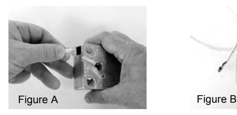
Installation Instructions for Model 2007 D•Drive Safe Lock
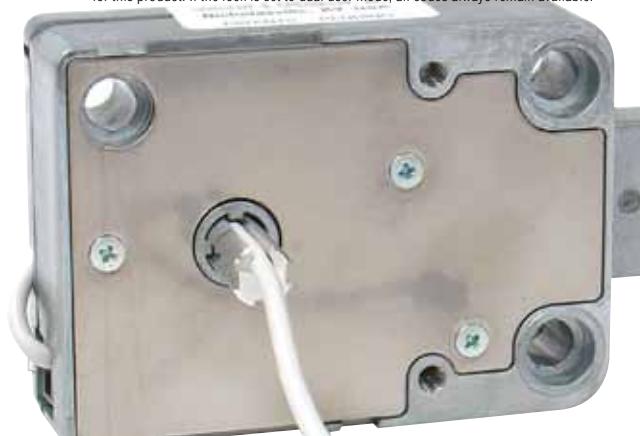
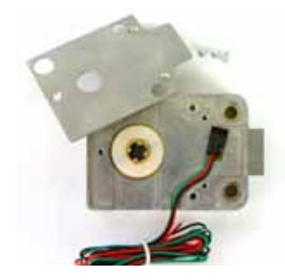
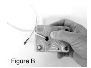
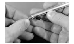
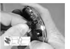
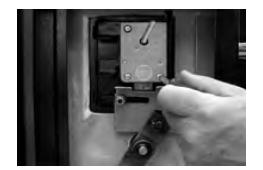
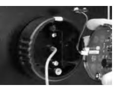
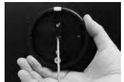
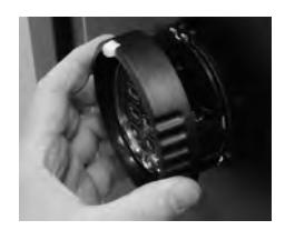
The Model 2007 is a non-handed electronic safe lock. It will be necessary to plug the provided cable into the lock. This is a phone-type connector that will only insert one way (Figure A). Make sure it is fully inserted and locked into the lock case receptacle. The lock cable must to be routed in the recessed channel in the lock's cover. Figure B shows the proper cable placement The cable runs through the opening of the case and on through the safe's spindle hole to the keypad.
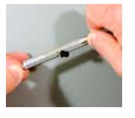
1. Measure the safe's door thickness (distance from the mounting surface for the lock to the mounting surface for the keypad. Add ¾" (19 mm), and cut the aluminum spindle to this length.
7. If not already attached, plug the battery connector cable into the white receptacle on the back of the keypad.
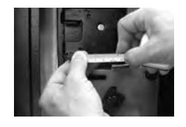
2. Insert the lock cable into the spindle slot as shown. Then slide the cable through the length of the slot.
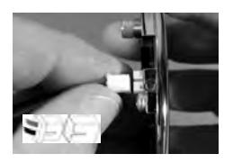
8. Plug the lock cable into the black receptacle on the back of the keypad. Note that there are two raised ridges on the cable plug and two matching slots in the keypad receptacle. Align these features before inserting the plug into the receptacle.
3. As you slide the last bit of cable through the spindle slot, place the spindle into the lock body cam. The spindle and cam are configured to mate together.
9. Place the lock cable into the recessed area of the keypad provided for it on the left side.
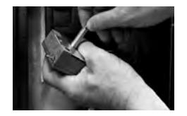
4. Place the end of the lock cable through the safe door from inside. Pulling gently on the cable insert the lock with attached spindle through the safe door so that it can be attached to the door's mounting plate with the three screws provided.
10. Place the battery cable through the slot at the base of the battery cable compartment and place the remainder of the cable in the compartment.
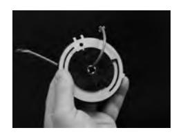
5. Place the lock cable through the center of the keypad base as shown.
11. Keeping the lock cable and the battery cable in their respective compartments, place the keypad onto the base. The top seats into the base first, then the bottom.
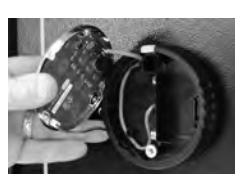
6. Pulling gently on the cable, move the keypad base against the safe door, and attach it using the two machine screws provided. Do not tighten beyond 15 inch-pounds (1,695 Nm).
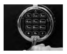
12. Install and tighten the keypad holding screw as shown. Use the one-way security screw for EN1300 applications. The Phillips screw is acceptable for all other applications. Once the screw is in place, cover it with the self-stick S&G logo after peeling the protective film off of the logo.
Sargent & Greenleaf, Inc. Sargent & Greenleaf S.A. A Wholly Owned Subsidiary of Stanley Security Solutions, Inc. 9, chemin du Croset PO Box 930, Nicholasville, KY 40356 1024 Ecublens, Switzerland

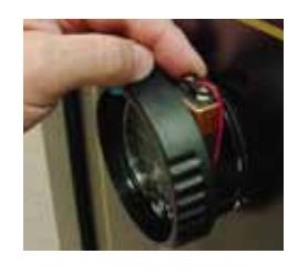
13. To install the battery, pull the keypad tab out slightly and turn the keypad ring counterclockwise. The ring will pull out from the base far enough to reveal the battery connector. Attach the battery and place it in the battery compartment.
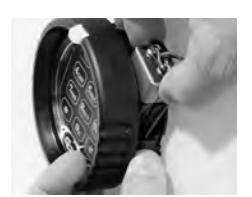
14. Push the keypad ring back against the base and turn it clockwise until it clicks into place. Test the lock function at least three times with the door open before closing the safe.
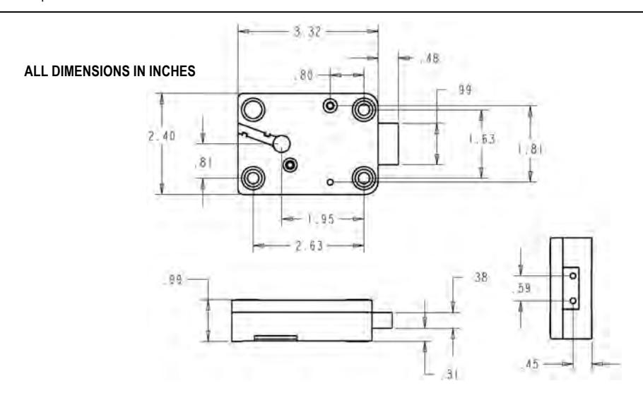
2007 D•Drive Specifications
Attaching Screws: Use only the screws provided with the lock. They must engage the mounting plate by at least four full threads. Do not use lock washers or thread sealing compounds.
Recommended Attaching Screw Torque: 30 to 40 inch-pounds (33,9 to 45,2 Nm) for the lock body. No more than 15 inch-pounds (1,695 Nm) for the keypad base attaching screws.
Minimum Lock Cable (Spindle) Hole Diameter: 0.375 inch (9,5 mm) Maximum Lock Cable (Spindle) Hole Diameter: 0.406 inch (10,3 mm)
Lock is Designed to Move: 2.5 lbs. (11,12 Newtons) continuous / 10 lbs. (44,48 Newtons) maximum
Lock Bolt Maximum Free Movement: 0.352 inch (8,95 mm) 0.109 inch (2,77 mm) remains outside the edge of the lock case when bolt is fully retracted.
Maximum Bolt End Pressure: lock is designed to withstand at least 225 lbs. (1000 Newtons)
Maximum Bolt Side Pressure: safe and container boltwork or locking cam designs must never apply more than 225 lbs. (1000 Newtons) of side pressure on the lock bolt.
Mounting Environment: The lock body is designed to be mounted inside a secure container. The container must be constructed to offer protection against physical attack directed at the lock. The amount of protection is dependent on the desired level of security for the system as a whole. Lock protection may include barrier materials, relock devices, thermal barriers, thermal relock components, or any combination of these. Relock device attaching screws must NOT be longer than the depth of the tapped hole provided in the lock case.
A minimum distance of .150 inch (3,8 mm) is recommended between the end of the lock case and the closest approach of the safe's blocking bar or cam plate (which is normally blocked by the extended lock bolt). Maintaining this clearance will allow the lock to deliver optimum performance.
Code Restrictions: Personal data that can be related to a code holder, such as a birth date, street number, or phone number, should not be used in creating a lock code. Avoid codes that can be easily guessed
Note: Every installation of this product must comply with these requirements and those in the product installation instructions to qualify for the manufacturer's warranty and to comply with EN1300 requirements.
Sargent & Greenleaf, Inc. Sargent & Greenleaf S.A. A Wholly Owned Subsidiary of Stanley Security Solutions, Inc. 9, chemin du Croset