Sargent & Greenleaf Mechanical and Safe Deposit Key Operated Safe Locks 6800 Install and Change
Open the original PDF document
View PDFModels 6860, 6870, 6880 Changeable Double Bitted Key Lock
Changing Instructions
The Sargent & Greenleaf Model Key Lock combines ease of key changing with a very high level of security. Its advanced design makes it easy to operate and easy to change keys. Follow these instructions carefully to get the best possible service from your lock.
INTRODUCTION
The key changing procedure is very simple. Follow these basic precautions:
- Read this entire page before you begin to change the keys.
- Keep the safe door open until the lock has been successfully changed to new keys and checked.
- Never force the lock or key.
- Always keep your key(s) in a safe place.
- If a key is lost or misplaced, change the lock to a new key as soon as possible, even if the original key is recovered.
KEY CHANGING PROCEDURE
- Step 1. Open the safe door. If the door incorporates boltwork, turn the safe handle to extend the bolts fully.
- Step 2. With the door open, turn the key counterclockwise to its stop, and remove it from the lock.
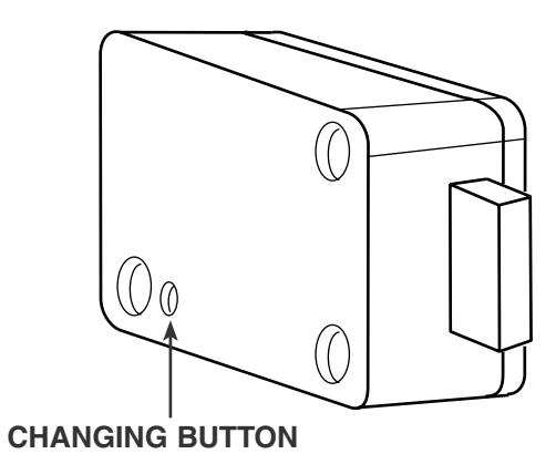
- Step 3. Locate the changing button on the back of the lock. Use a probe (such as the tip of a ball point pen) to depress the button. Keep the button depressed for Step 4.
- Step 4. Insert the old key and turn it clockwise 180º until it reaches its stop. Release the changing button and remove the key.
- Step 5. Insert the new key and turn it counterclockwise 180º to its stop. Remove the new key. Your lock is now set to the new key, and the old key is no longer operable.
- Step 6. Check the operation of the new key(s) in your lock at least three times before closing the safe door.
One Security Drive, Nicholasville, Kentucky 40356 9, chemin du Croset, 1024 Ecublens, Switzerland Phone (859) 885-9411 FAX (859) 887-2057 Phone 41-21-691-9583 FAX 41-21-691-5349 Internet: www.sargentandgreenleaf.com catalog revision 7/7/03

Models 6860, 6870, 6880 Changeable Double Bitted Key Lock
Installation Instructions
INTRODUCTION
Follow these basic precautions:
- The bolt of the Key Lock can withstand an end load up to 1.8 lbs. (8 N). Forces greater than this amount may prevent the lock from working properly.
- The key requires a minimum keyhole diameter of 1 ⁄2 inch (12,7 mm). If a guide tube is used with the lock, the minimum diameter increases to 11⁄16 inch (17,5 mm).
- Installer modifications to the Key Lock are not covered by the manufacturer's warranty.
- Take precautions to prevent metal shavings, safe insulation, paint, weld spatter, or other foreign material from entering the lock.
- Make sure the lock is not installed in a manner that will allow objects to come in contact with the changing button.
- The lock can be mounted right-hand (RH), left-hand (LH), vertical-up (VU), or vertical-down (VD).
- The safe must incorporate a relock device, or have a plate of at least 12-gage steel attached to the back of the lock. Plate dimensions are given in the drawing at right. Attaching screws must be inserted into the blind holes on the lock's back.
- The lock should only be serviced and lubricated by trained service personnel. Improper service or lubrication will damage the lock and void the manufacturer's warranty.
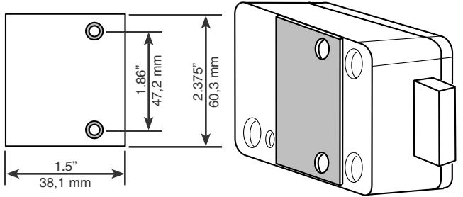
ATTACH PLATE TO LOCK USING (2) 8-32X3⁄ 8" SELF-TAPPING SHEET METAL SCREWS
INSTALLATION PROCEDURE
- Step 1. Insure that the mounting surface for the lock is smooth and flat, and that the keyhole is perpendicular to the mounting surface.
- Step 2. Attach the lock to the mounting surface using three 1 ⁄4 -20 or three M6- 30 machine screws, depending on the dimensions of the screw threads in the mounting surface.Attach the safe relock device or recommended back plate (see illustration above).
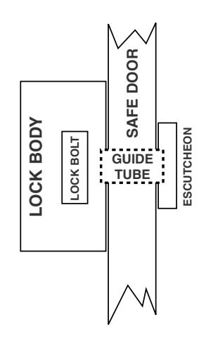
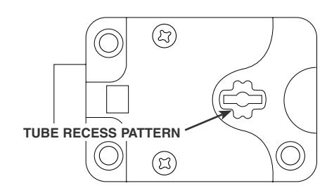
- Step 3. A guide tube should be used on insulated and composite safes. The tube must be cut to a length equal to the safe door thickness plus 3 ⁄16 inch (5mm). This will cause the tube to mate with the pattern surrounding the keyhole and the pattern in the underside of the escutcheon. Remove all sharp edges, burrs, and metal shavings created when the tube is cut.
- Step 4. Attach the escutcheon to the outside surface of the safe door over the keyhole.
- Step 5. Check the operation of the key in the lock. There should be no binding or scraping of the key against the tube or the sides of the keyhole. It should turn easily and smoothly.
- Step 6. Check the operation of the new key(s) in your lock at least three times before closing the safe door.
- Step 7. Make sure the lock bolt does not drag or bind against the safe's boltwork or door frame (rebate).