Sargent & Greenleaf Mechanical and Safe Deposit Group 1 and Group 1R Mechanical Locks S&G 8500 Installation Changing
Open the original PDF document
View PDFInstallation and Combination Changing Instructions
8500 Series MP Safe Locks
Models 8550 (Group 1) and 8560 (Group 1R)

NOTE: READ COMPLETE INSTRUCTIONS BEFORE INSTALLATION
These instructions should be followed when installing Sargent & Greenleaf 8500 Series locks.
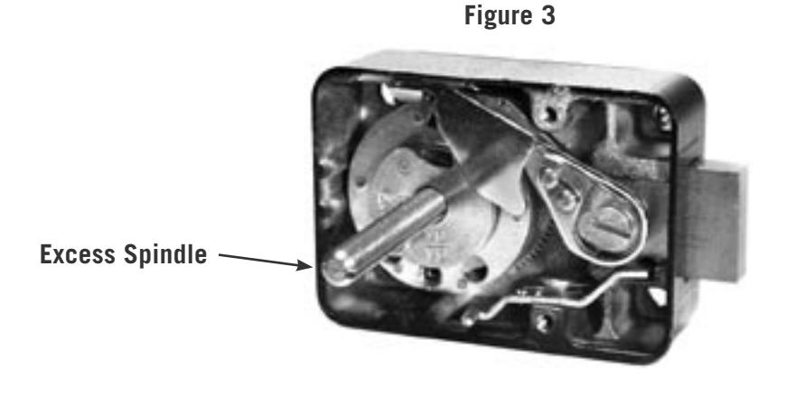
Caution: Lock mounting bedplate and dial ring mounting surfaces must be parallel. Dial ring center line must be precisely aligned with lock spindle center line (see Figure 3).
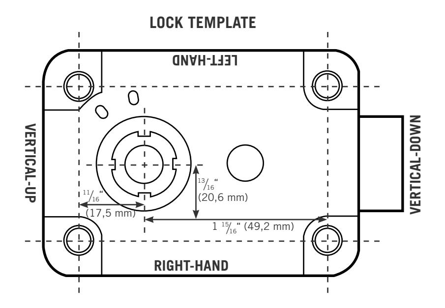
Locate exact position you want for the lock on the mounting plate. Using the template on the last page of these instructions, drill and tap four holes for the attaching screws (1/2 X 20).
Using the template, drill a hole for the spindle through the mounting plate. For applications requiring an optional tube, the hole should be diameter. For locks to be used without tubes, the hole should be " diameter.
It is necessary to remove only the cover when attaching the lock. All other parts should remain in place as received from the factory.
INSTALLATION INSTRUCTIONS
1. Remove the lock cover. Place the lock bolt in the extended position and the accelerator spring in the loaded position (Figure 1). CAUTION: Do not remove the drive cam.
Accelerator Spring in Released Position
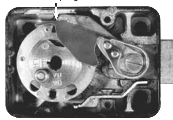
Figure 1 MP Lock Illustrations
Accelerator Spring in Loaded Position
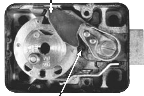
Torque Adjusting Gear
Sargent & Greenleaf, Inc.
Copyright® 2002, Sargent & Greenleaf, Inc.
PO Box 930, Nicholasville, Kentucky 40356 USA Phone (859) 885-9411 Phone (800) 826-7652 FAX (859) 887-2057 FAX (800) 634-4843
Sargent & Greenleaf S.A.
9. chemin du Croset 1024 Ecublens, Switzerland Phone 41-21-691-9583 FAX 41-21-691-5349
- 2. Mount the lock in place with four X 20 attaching screws (provided).
- 3. Attach the dial ring by loosely installing the attaching screws to hold the dial ring in place for alignment. The dial ring opening index should be at the 12 o'clock center position.
- 4. To install the dial, hold the drive cam in place with one hand and thread the dial/spindle assembly into the cam until the dial comes to a stop against the surface of the dial ring.
Caution: When threading the dial into the cam, do not allow the cam to slide outward against the accelerator spring. The accelerator spring can be easily damaged in this manner.
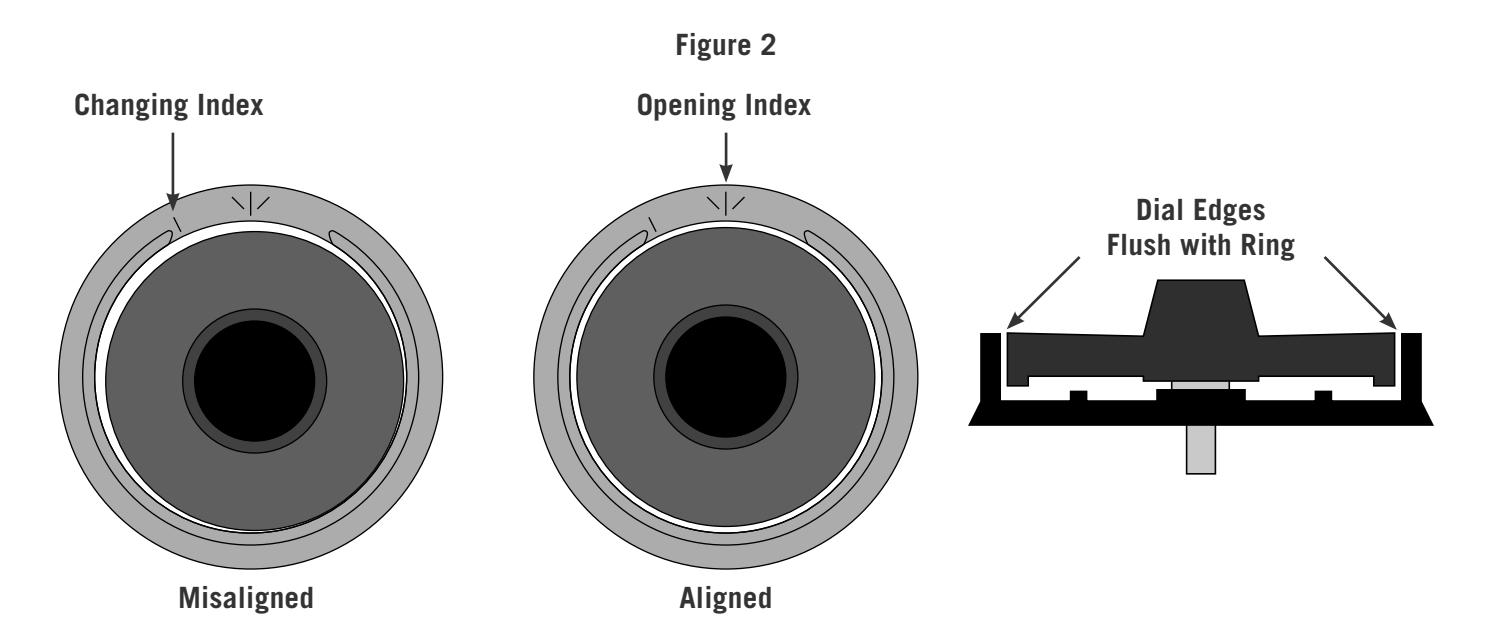
5. The alignment of the dial and ring is critical to the proper operation of the lock. Perfect alignment must be obtained. The dial should be flush and centered with the surface of the dial ring for true centering (Figure 2).
- 6. Measure the excess spindle that projects beyond the drive cam (Figure 3)
- 7. Remove the dial, cut off the excess spindle, and remove any burrs from the end. You may also find that the spindle threads more easily into the drive cam after cutting if the spindle end is beveled slightly.
- 8. Tighten the dial ring screws.
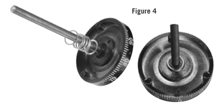
- 9. Place a flat washer, the compression spring, and another flat washer over the spindle and into the recess at the dial hub (Figure 4).
- 10. Insert the dial into the lock, but remember that you should not allow the cam to slide outward against the accelerator spring, possibly damaging it. Hold the drive cam in place, positioned for its gate to receive the nose of the drop lever, and thread the dial into the cam until the dial stops.
- 11. Turn the dial counterclockwise until zero is aligned with the opening index of the dial ring, then turn the dial one turn farther counterclockwise. When this is done, the proper spindle spline keyway and drive cam spline keyway should be closely aligned (vertical-up—VU, right-hand—RH, etc.).
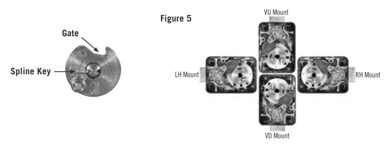
12. Insert the spline key with the tip toward the edge of the cam. Tap in lightly. Be very careful to avoid striking the stainless steel roller that is attached to the top surface of the drive cam. With the spline key inserted fully, the dial must turn freely with no rubbing or interference.
Note: Before installing the lock's cover, check for proper in and out travel of the dial to make sure the accelerator spring operates correctly.
- 13. Turn the dial at least one complete revolution in either direction and then stop at zero. The accelerator spring should now be in the loaded position.
- 14. Hold the cover in place on the lock and push the dial in at zero. Release the dial. Remove the cover and check the position of the accelerator spring. It should be in the released position. If the accelerator spring is not in the released position, the dial has not been backed out of the cam far enough, and the condition must be corrected. Remove the spline key, hold the cam, and rotate the dial one additional full turn counterclockwise. Install a new spline key and repeat steps 13 and 14.
- 15. Turn the dial at least one complete revolution in either direction, then stop at 50. The accelerator spring should now be in the loaded position.
- 16. Hold the lock cover in place and push the dial in at 50. The accelerator spring should not release. If the accelerator spring does release, the spindle must be turned clockwise into the cam one revolution and the lock checked again, beginning at step 13.
- 17. Dial the factory combination (4 times left to 50, right to 0, push in, let the dial out, turn right until the dial comes to a stop at about 85) and observe the drop lever falling into the drive cam. Repeat this step at least three times, checking to make sure the drop lever falls into the drive cam gate each time.
- 18. When the accelerator spring is operating properly, the cover may be attached to the lock and the new combination set.
FOR LOCKS INSTALLED WITH OPTIONAL TUBE KIT (PART NO. U24)
- 1. Install the optional tube kit to the lock body, then fasten the lock to the mounting plate.
- 2. Measure and mark the tube where it exits from the spindle hole at the front of the safe door. Remove the lock and move your mark .120" (3 mm) farther toward the end of the tube. This slight extra length will protrude through the front of the safe door and seat into the underside of the dial ring bearing when the lock is re-installed. Cut off the excess tube at your new mark.
- 3. Remove any burrs from the end of the tube, replace the lock and ring on the door, and proceed with Step 4 of the installation instructions (page 2).
DIALING THE COMBINATION TO OPEN THE LOCK
Before operating the lock or changing the combination, read these instructions thoroughly.
On the dial ring are two index marks. The one at the top is for normal dialing and opening. The index to the left is provided for use only when changing the combination.
Turn the dial slowly and steadily. If, after turning the correct number of revolutions, any number is turned beyond the index mark, the entire series of combination numbers must be re-dialed. You cannot back up to a number if you pass it when you meant to stop on it. Each time a selected number is aligned with the opening index, it counts as one revolution, even if you only have to turn the dial a few numbers to achieve the initial alignment.
CAUTION: The dial should not be pushed in until the combination has been dialed and the dial returned to zero at the opening index.
TO UNLOCK ON A FACTORY COMBINATION
- 1. Turn the dial counterclockwise (left) , stopping when 50 is aligned with the opening index the fourth time.
- 2. Turn the dial clockwise (right), stopping when 0 is aligned with the opening index the first time.
- 3. With 0 aligned at the opening index, push the dial in firmly, then release it to activate the lever assembly.
- 4. Turn the dial clockwise until the bolt retracts. The dial should come to a positive stop at about 85. If the combination has been correctly dialed, the safe or cabinet may be opened.
TO LOCK
Turn the dial counterclockwise (left) at least five complete revolutions for maximum security.
COMBINATION CHANGING FROM 50 - 0
Make up a new combination, selecting three numbers of your own choosing. Do not set the third number of the combination between 90 and 99 or 0 and 10. This area is known as the forbidden zone . Adjacent combination numbers should be at least 5 numbers apart. Numbers that end with 0 or 5 should not be used for all combination numbers. Do not use strictly ascending (ex. 22-45-83) or descending (ex. 83-45- 22) combination sequences. Also, do not use numbers someone could easily guess.
Caution: Only use change key U8 or U9 on the 8500 series lock. Other keys will not function properly and may damage the lock.
- 1. Turn the dial counterclockwise, stopping when 50 is aligned with the changing index the fourth time.
- 2. Leave the dial on 50 at the changing index and insert the change key into the hole in the back of the lock. Insert the key until the wing is entirely inside the lock and the key comes to a positive stop.
WARNING: Never insert the change key into the lock when the cover is removed. Always be certain the change key is entirely within the lock before turning the key.
- 3. Turn the key one quarter turn counterclockwise. With the change key in this position, turn the dial counterclockwise, stopping when the first number of the newly selected combination aligns with he changing index the FOURTH time.
- 4. Turn the dial clockwise, stopping when the second number of the combination is aligned with the changing index the THIRD time.
- 5. Turn the dial counterclockwise, stopping when the third number is aligned with the changing index the SECOND time. Holding the dial in this position, turn the change key one quarter turn clockwise to relock the wheels with the new combination installed. Remove the change key from the lock.
The new combination you have selected is now set. After changing the opening combination, the lock should be opened and locked several times with the safe door open. Once the new combination has been successfully tested, the safe door can be closed and locked.
TO UNLOCK ON A SAMPLE COMBINATION OF 50 - 25 - 50
- 1. Turn the dial counterclockwise, stopping when 50 is aligned with the opening index the fourth time.
- 2. Turn the dial clockwise, stopping when 25 is aligned with the opening index the third time.
- 3. Turn the dial counterclockwise, stopping when 50 is aligned with the opening index the second time.
- 4. Turn the dial clockwise, stopping when 0 is aligned with the opening index the first time.
- 5. When 0 is aligned with the opening index, push the dial in firmly, then release it to activate the lever assembly.
- 6. Turn the dial farther clockwise until it comes to a positive stop near 85, indicating that the lock bolt has retracted. If the combination has been correctly dialed, the safe or cabinet may be opened.
This procedure can be used with any three number combination, substituting selected numbers for the numbers 50 - 25 - 50.
CAUTION: The dial should not be pushed in at 0 until all three numbers have been dialed and 0 is aligned with the opening index.
COMBINATION CHANGING FROM A SAMPLE COMBINATION OF 50 - 25 - 50
- 1. Turn the dial counterclockwise, stopping when 50 is aligned with the changing index the fourth time.
- 2. Turn the dial clockwise, stopping when 25 is aligned with the changing index the third time.
- 3. Turn the dial counterclockwise, stopping when 50 is aligned with the changing index the second time.
- 4. Leave the dial with the last number at the changing index and insert the change key in the hole in the back of the lock. Insert the key until the wing is entirely inside the lock and comes to a positive stop.
- 5. Turn the key one quarter turn counterclockwise. With the change key in this position, turn the dial counterclockwise, stopping when the first number of the newly selected combination aligns with he changing index the FOURTH time.
- 6. Turn the dial clockwise, stopping when the second number of the new combination is aligned with the changing index the THIRD time.
- 7. Turn the dial counterclockwise, stopping when the third number of the new combination is aligned with the changing index the SECOND time. Holding the dial in this position, turn the change key one quarter turn clockwise to relock the wheels with the new combination installed. Remove the change key from the lock.
The new combination you have selected is now set. After changing the opening combination, the lock should be opened and locked several times with the safe door open. Once the new combination has been successfully tested, the safe door can be closed and locked.
Important: do not select codes such as birthdays or other predictable sequences which could provide a correlation between the user and the safe combination.
TORQUE ADJUSTMENT
The torque adjustment feature allows the wheel pack tension to be adjusted for maximum security. To adjust torque, remove the lock cover and insert a hex wrench into the adjusting gear (see Figure 1). Turn clockwise to increase torque or counterclockwise to decrease torque. This adjustment should only be performed by a skilled technician using a specialized torque measuring tool.
Note: Manipulation proof locks should not be adjusted to less than 18 inch-ounces of dialing torque.
CAUTION: Whenever the lock's torque setting is changed, the combination must be reset (18-20 in-oz).
SERVICING (should only be performed by a qualified locksmith or safe technician)
Periodic servicing will extend the life of your lock and is essential for maintaining security. To perform proper service, follow these instructions.
- 1. Remove the lock cover.
- 2. Remove the lever screw and lever assembly. Be sure to remove the lever control tension spring (small "Z" spring) so you won't misplace it.
- 3. Using a pair of side cutters, grip the head of the spline key as close as possible to the surface of the drive cam. Lift straight up, being careful not to bend the key. The edge of the case may be used for leverage as long as minimal force is used.
- 4. Unscrew the dial and spindle assembly from the lock. Remove the drive cam.
- 5. Remove the Spirolox® retainer from the top of the wheel post.
- 6. Remove the wheels and associated parts. Place them in sequence so they can be re-installed in the proper order.
- 7. Remove the lock bolt. Do not misplace the detent ball or detent spring.
- 8. Remove the dial and spindle assembly from the dial ring.
CAUTION: Remove the washers and spring from the dial carefully so they can be re-installed later.
The lock is now completely disassembled and ready for servicing.
SERVICE AND REASSEMBLY
- 1. Tighten the attaching screws for the dial ring and lock body.
- 2. Wipe each wheel, the wheel post, and other bearing surfaces clean. Wipe the complete interior of the lock case clean.
Note: S&G recommends Novagard G322L® Versilube, Dow Corning Gn Metal Paste®, or Shell Aeroshell 22® for lock lubrication. Use of other lubricants will void the product warranty.
- 3. Lightly (means a thin film) grease the bolt where it normally rubs against the lock case. Install the detent spring and detent ball before sliding the bolt back into the lock case. It will be necessary to depress the relock trigger to slide the bolt back into the case.
- 4. Be sure to carefully examine each wheel part as well as the cam and lever assembly to make sure nothing is worn or damaged.
- 5. Lightly grease the bearing surface of the wheel post and drive cam bearing. Replace the wheels and parts exactly as they were before disassembly. Reset the wheel pack torque to a value between 18 and 22 inch-ounces. Screw the dial/spindle assembly and cam together until snug. Hold the cam and turn the dial back one complete turn, then align the spline keyways. Insert the spline key. For proper key installation, see Figure 6 on page 3.
IMPORTANT: It is recommended that a new spline key be used each time the lock is serviced.
- 6. Lightly grease the bearing surface of the lever bushing and install the lever. Tighten the lever screw snugly and carefully. Position the lever control tension spring. Be careful not to bend the accelerator spring. Lever screw torque should be between 22 and 26 inch-pounds).
- 7. Install the lock cover. Make sure the cover screws are tight.
- 8. Reset the combination.
- 9. Check the combination at least three times before locking the safe.
ERRORS
The most frequent error in the changing procedure is dialing the number to the wrong index. Occasionally all the numbers may be dialed to the opening index rather than the changing index. More often, dialing part of the combination to the changing index and part to the opening index occurs. As long as the door is open, the error is easily corrected.
PROCEDURE
- 1. Remove the cover from the lock.
- 2. Insert a straightened paper clip or similar instrument ( NOT the change key) in the square keyways of the wheels.
- 3. Rotate each wheel until all the keyways are in perfect alignment directly over the small hole in the bottom of the case where the tip of the change key seats during normal changing operations. There are two holes in the bottom of the case. Use the one that normally lines up with the change key hole in the lock cover (when the cover is in place on the lock body).
- 4. Replace the cover and insert the change key. Replace the cover screws. NEVER INSERT A CHANGE KEY INTO THE LOCK WHEN THE COVER IS REMOVED! Always be certain that the wing of the change key is entirely within the lock before turning the key.
- 5. Turn the change key one quarter turn counterclockwise and dial the new combination to the changing index. Once all the combination numbers have been entered into the lock, turn the key back and remove it from the lock.
- 6. With the combination now set, try the combination at the opening index at least three times before closing the door. You should also be able to dial the combination 1⁄2 number high and 1⁄2 number low on all combination numbers.