Sargent & Greenleaf Electronic Safe Lock Series S&G Comptronic 6150 Input Panel
Open the original PDF document
View PDFComptronic Model 6150 Safe Lock System Input Panel User Guide
Table of Contents
| 1. General Information2 | |
|---|---|
| 1.1—Your Locking System Hardware Component | 2 |
| 1.1.1—Programming and Audit Trail Software | 2 |
|
1.2—Power Supply
|
2 |
| 1.3—In Case of Power Failure | 2 |
|
2. Operating the Lock
3 |
|
|
2.1—User IDs and PIN Codes
|
3 |
| 2.2—"Special" ID Position Privileges | 3 |
|
2.3—Operating the Lock from the Input panel
|
4 |
| 2.4—"Penalty Time" Lockout Feature | 4 |
| 2.5—Duress Feature (must be activated by connecting to an alarm system) |
5 |
| 2.6—Keypad Tamper Alarm | 5 |
|
3. Programming the Lock from the Input panel
5 |
|
| 3.1—Input Panel Commands | 5 |
| 3.2—Command 22: For Managers and Programmer: Add, delete, or change PIN codes | 6 |
|
3.2.1—Command 22: Users Changing their own PIN Codes
|
8 |
| 3.3—Command 28: View Audit Trail at LCD or Download the Audit Trail | 8 |
| 3.4—Command 43: Show Lock Identity (serial number and firmware version) |
11 |
|
3.5—Command 52: Long Close
|
12 |
| 3.6—Command 55: Enable & Disable User PINs in Manager/Employee Modes |
13 |
|
3.7—Command 57: Show Lock Status
3.8—Command 61: Setting Manager/Employee Mode 1 or Mode 2 |
14
15 |
| 3.9—Command 62: Check the clock chip | 15 |
|
3.10—Command 72: Short close
|
15 |
| 3.11—Command 73: Set date | 16 |
| 3.12—Command 75: Uploading Data from the Touch Key to the Lock | 16 |
| 3.13—Command 78: Set time | 17 |
|
3.14—Command 79: Set Winter/Summer mode
|
17 |
|
3.15—Command 86: Save the lock settings to the Touch Memory Key
|
19 |
| 4. Programmable Functions (Must use PC Software)19 | |
| 4.1—Single or Multiple Lock Modes | 19 |
| 4.2—Time Delay | 19 |
|
5. Configuring the Lock Access Type
20 |
|
|
5.1—Touch Memory Required with PIN
|
20 |
| 6. Touch Memory Keys21 | |
| 6.1—Touch Memory Key Functions | 21 |
| Appendix22 | |
| A.1—Changing the Clock Chip | 22 |
| A.2—Specifications for the Comptronic Model 6150 | 22 |
|
A.3—Power Supply Requirements
|
23 |
| A.4—ID Position Worksheet | 24 |
|
Warranty
25 |
1. General Information
1.1—Your Locking System Hardware Components
The Model 6150 Electronic Lock system has several components:
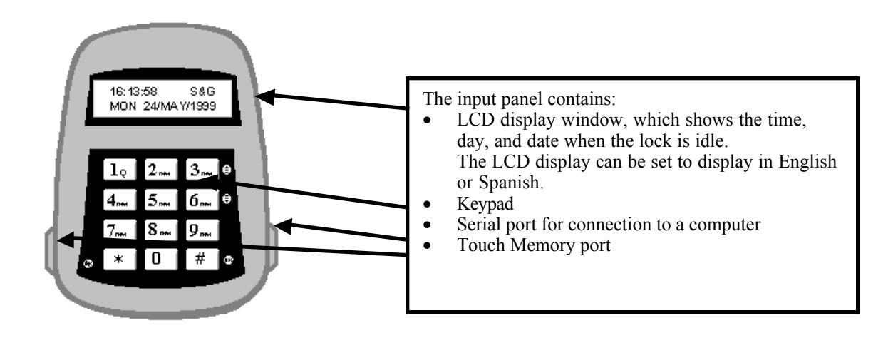
- A Input panel. The input panel contains a keypad and an LCD display window. It controls one or two separate locks. The input panel has a serial port for direct connection to a computer, and a Touch Memory® port for use in transferring information between the input panel and the computer by means of a Touch Memory Key.
- One or two electro-mechanical safe locks.
- An Electronic Control Unit, or ECU, which is secured inside the safe.
- An external DC power supply, which provides power both to the input panel and to the drive motor for the lock.
1.1.1 Programming and Audit Trail Software
A Windows 95/98 based software program is required when programming Time Delay, Time Lock, and user access methods. It is also required for Audit Trail administration. Reference the Programming and Operations Guide, part number 630-530 for programming the 6150 with software instructions.
1.2—Power Supply
A DC transformer connected to an external power supply powers the Model 6150 Electronic Control Unit (ECU). The ECU provides power to the input panel and to the locks. The ECU stores programming information, including PINs, in non-volatile memory. The programming will not be affected by an interruption of power to the unit.
1.3—In Case of Power Failure
Input panel
In the event of a power failure the lock will remain locked. Power must be restored before it can be opened. When power is initially restored, the lock will be in the locked state, regardless of its status at the time power was lost. The lock cannot be opened inadvertently as a result of power outage or interruption.
An emergency battery cable is available, (Part Number 6151-037-000) which uses two 9Volt Alkaline batteries to open the lock a limited number of times. Do not use the emergency battery cable for normal operations.
Touch Memory® is a registered trademark of Dallas Semiconductor.
2. Operating the Lock
2.1—User IDs and PIN Codes
There are 21 user IDs, which identify the type of user, they are:
ID 00 is the programmer position
IDs 01 and 02 are manager positions
IDs 03-20 are individual user positions
Each user has an individual PIN code to access the lock. User PIN codes may be 6, 7, or 8 digits (characters), and are user changeable.
The following table summarizes the privileges and capabilities of each ID position. These privileges are set at the factory. Changes can be made using the computer program.
| User ID | 00 (Programmer) | 01, 02 (Manager) | 03-20 (User) |
|---|---|---|---|
|
Capabilities: Can this PIN Code
|
|||
| open the lock? | No | Yes | Yes |
| bypass the time delay? | No |
Programmable*
(see "Special" PIN Codes below) |
Programmable*
(see "Special" PIN Codes below) |
| … bypass time lock? | No | No | No |
| program the lock? | Yes | Limited | No |
| modify their own PIN? | Yes | Yes | Yes |
| modify other users' PINs? | Yes (all) | Yes (except the | No |
| enable the short close? | Yes |
Programmer ID)
Yes |
No |
| enable the extra close? | Yes | Yes | No |
| access the audit trail? | Yes | Yes | No |
2.2—"Special" ID Position Privileges
Using the software program an ID position can be given three special access conditions. They are:
- 1. Time Delay Bypass—allowing them to access the lock without having to wait for the time delay.
- 2. Second PIN Required—this is a special dual control mode for a specified ID, requiring the ID position to have a second PIN entered before they can open the lock.
- 3. Both Time Delay Bypass and Second PIN Required.
2.3—Operating the Lock from the Input panel
To open the lock from the input panel, you must enter your user ID and PIN numbers. The procedure is as follows:
- 1. First press the # key. The lock will beep once, and the LCD display will prompt you for your ID.
- 2. Enter your ID and press # to move the cursor to the next line.
- 3. Enter your PIN. Press # again. If there is only one lock on a door it will open.
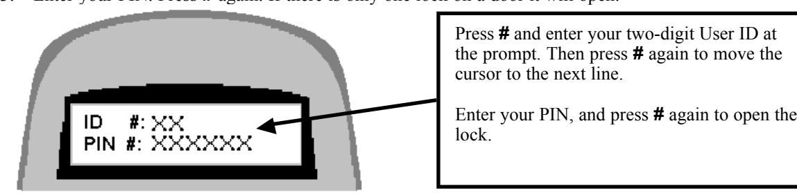
The LCD displays X s in place of the numbers you enter, for security reasons. Each time you press an alpha/numeric key, the input panel beeps once, and the cursor on the LCD screen moves to indicate your entry.
4. If there are locks on two doors, the LCD will prompt you to select the door to be opened.

Choose 1 or 2 Press #
The LCD displays which lock is opening (locked or unlocked ).

ENTRY ERRORS
If you make a mistake in your entry and press # , the lock beeps a series of short, fast beeps, and the following message is displayed. Wait for the lock to clear, (the date and time displays) and start your entry again.

You may also cancel an entry by pressing the * button, IF you haven't already pressed #.
2.4—"Penalty Time" Lockout Feature
If four (4) consecutive invalid PINs are entered, either to open or program the lock, the lock automatically goes into "penalty time" for 15 minutes. At the end of the penalty time, enter a valid PIN to open the lock. Any entry during penalty time has no effect on the lock or time.
Note: There is no way to bypass the 15-minute penalty time lockout.
2.5—Duress Feature (Must be activated by connecting to an alarm system)
To send a duress alarm to the alarm center, enter a user code that is one number higher or lower on the last number of the user's normal PIN Code and press the # key.
For example, if the normal user code is 1 2 3 4 5 6 for PIN position 02, the user can activate the duress alarm by entering 0 2 1 2 3 4 5 5 or 0 2 1 2 3 4 5 7, followed by #. If the user code ends in 0, use 1 or 9 to activate the duress alarm.
All user codes can send the duress signal at any time. It can also be sent during programming sequences.
2.6—Keypad Tamper Alarm
If an attempt is made to remove the housing from the input panel, a tamper-detect switch disables the lock. When in tamper alarm, a manager PIN code is required to clear it and open the lock. Any other valid user codes will not work, and the LCD will flash TAMPER ALARM for 15 seconds.
To clear the alarm, enter the manager code once. The TAMPER ALARM message displays on the LCD. Re-enter the same manager code within 10 seconds to disable the tamper alarm and open the lock.
The tamper condition is recorded in the audit trail history.
3. Programming the Lock from the Input panel
CAUTION! It is recommended all programming, testing, and employee training is conducted prior to uploading and activating the time lock schedule.
The programmer and manager IDs can program the lock. Most functions may be programmed into the lock in two ways:
- From the input panel keypad.
- From a remote computer terminal, using the Settings Editor in the 6150 Programming Software. Refer to the " Programming and Operations Guide ," Part No. 630-530
3.1—Input Panel Commands
To make programming entries from the input panel, first enter the command from this table, followed by an asterisk (*), for the procedure you want to perform. You will be prompted for your ID and PIN. Enter them as you would to open the lock, and then follow the prompts on the LCD.
IMPORTANT! For some procedures you'll be asked to confirm your selections. Use the # key for Yes and the * key for No .
| Command | Description/Function |
|---|---|
| 2 2 * | Add, delete, or change PIN codes |
| 2 8 * | View, print, or download the audit trail to the Touch Memory Key |
| 4 3 * | Show lock identity (serial number and master code) |
| 5 2 * |
Long close1
or extra close (no other functions available when enabled) |
| 5 5 * | Toggle the user PINS (manager/employee mode) |
| 5 7 * | Show lock status (i.e., open or closed) |
| 6 1 * | Toggle the manager/employee mode |
| 6 2 * | Check the clock chip (tells you the time remaining on the battery life) |
| 7 2 * |
Short close1
(no other functions available when enabled) |
| 7 3 * | Set date |
| 7 5 * | Load Touch Memory from the Touch Key to the lock |
| 7 8 * | Set time |
| 7 9 * | Set winter/summer mode |
| 8 6 * | Save lock settings onto a Touch Memory Key |
1 Caution: Be very careful when setting the long or short close! Once they are enabled, you will not be able to open the lock or access any programming functions during the close period.
3.2—Command 22: For Managers and Programmer: Add, delete, or change PIN codes
Follow these steps if you're a manager or programmer (ID 00, 01, or 02) adding, deleting, or changing PIN codes.
ADD OR CHANGE PIN CODE
Enter: 2 2 *
The LCD now asks for your ID and PIN:
ID #:
PIN #:
Enter: Your ID number (00-02) # Your PIN code (6, 7, or 8 digits) #
The LCD now asks for the ID number you want to add or change (1 or 2 digits).
Which PIN ID to
Change?
Enter: The ID number you want to add or change (1 or 2 digits). #
The LCD now asks for the new PIN (6, 7, or 8 digits) and to confirm it. Enter # after each PIN entry.
| New PIN: | |
| Confirm: |
If there are two doors, the LCD now asks whether this change is authorized for Door 1.
To Authorize Door 1? Y or N
Press: # (for Yes) or * (for No)
If you select # (for Yes), the change is now added to the door information. If you select * (for No), the PIN code isn't changed for that door.
If there is a second door, you'll now be asked if the change is authorized for Door 2.
To Authorize Door 2? Y or N
Press: # (for Yes) or * (for No)
The LCD now asks you to confirm the changes.
Authorized for
Door 1 and 2
Press: # (for Yes) or * (for No)
The LCD displays a message confirming the change.
CHANGE PASSED
Press: # to return to the time/date display.
DELETE PIN CODE
Enter: 2 2 *
The LCD now asks for your ID and PIN:
ID #:
PIN #:
Enter: Your ID number (1 or 2 digits) # Your PIN code (6, 7, or 8 digits) #
Which PIN ID to
Change?
Enter: The ID number you want to delete the PIN code for (1 or 2 digits). #
DO NOT enter a value in the "New PIN" or "Confirm" fields.
New PIN:
Confirm:
Press: # twice.
The LCD now asks if you want to delete the ID you entered. For example, if you entered ID 04, the LCD looks like this:
Do you want to
delete ID 04?
Press: # (for Yes) or * (for No)
The LCD confirms the deletion of the PIN code for the ID selected:
ID 04 Deleted
Press: # to return to the time/date display.
3.2.1—Command 22: Users changing their own PIN codes
CHANGE PIN CODE
Enter: 2 2 *
The LCD now asks for your ID and PIN:
ID #:
PIN #:
Enter: Your ID number (1 or 2 digits) # Your PIN code (6, 7, or 8 digits) #
The LCD now asks for a new PIN code. You must also confirm it.
New PIN:
Confirm:
Enter: The new 6-, 7-, or 8-digit PIN code. # Enter the new PIN code again to confirm. #
The LCD displays a message confirming the change.
CHANGE PASSED
Press: # to return to the time/date display.
3.3—Command 28: View Audit Trail at LCD or Download the Audit Trail
Use Command 28 to view or download the audit trail to a Touch Memory Key.
The lock maintains an audit trail of at least the 500 most recent events. You can view the audit trail on the LCD display, download it to the computer via the Touch Memory Key or direct serial port connection. Because the audit trail is held in non-volatile memory, power outages or disconnections do not alter it. Note that if you have a direct serial port connection, you don't need to use Command 28. You can view audit trail information on your PC using the Audit Viewer window of the 6150 software.
For each event, the audit trail records:
- User ID
- Event code (i.e., LOCK OPENED, AUDIT READ, WRONG PIN, etc.)
- Date
- Time
To keep the memory from filling up with multiple repetitions, consecutive repetitions of certain events (e.g., Startup and Tamper Alarm ) are not recorded. The audit trail also does not record actions attempted when the lock is in Penalty Time , although the start of the Penalty Time period itself is recorded. VIEW THE AUDIT TRAIL
Enter: 2 8 *
The LCD now asks for your ID and PIN:
ID #:
PIN #:
Enter: Your ID number (1 or 2 digits) # Your PIN code (6, 7, or 8 digits) #
The LCD displays the options available for the audit trail.
1-PRINT 2-TOUCH
3-DISPLAY AUDIT
Note: The local PRINT option on the LCD when requesting audit trail is not currently available. If this is selected the LCD will indicate PRINTING AUDIT TRAIL. No data is lost.
Press: 3
The LCD displays instructions for view the audit trail. Use 3 for _and 6 for _.
_ or _ to SCROLL
* QUIT
The audit trail entries will look something like this:
06OCT1999 09:26
S1: AUDIT READ
Enter: Must press * to return to the time/date display
The following table explains the LCD possible audit trail messages. An "X" in this table represents a variable number such as a lock number or a PIN code.
| LCD Display | Description of Event |
|---|---|
| START UP | System Power-up |
| TAMPER DETECT | Displays the time the tamper is initially detected and lockout occurs. |
| DURESS CODE | Displays the time the duress PIN is entered. |
| IN PENALTY | Displays the time the "In Penalty" period begins. |
| WRONG PIN | An invalid PIN was entered. |
| PIN ENTERED | Displays when the first of two PINs is entered in Dual Control mode. |
| DOOR CFG MOD | The door configuration parameter is changed. |
| AUDIT READ | Indicates that the Audit Trail has been read (in any manner: PC, LCD, |
| printer) | |
| NEW HOUR/DATE | The date and time has been modified. |
| L CLS STARTED | Long Close started. |
|---|---|
| S CLS STARTED | Short Close started. |
| W/S CHG PASS | The Winter/Summer mode was successfully changed. |
| PC CONNECT | The lock was connected to the PC. |
| PC CHG PASS | The lock program was changed via the PC. |
| PC CHG FAIL | An attempt to change the lock program via the PC was denied. |
| PROG TO PC | Programming information was sent from the lock to the PC. |
| HOLIDAY CHG | The holiday calendar was changed. |
| PANEL LOST | Communication from the panel was lost. |
| PANEL FOUND | Communication to the panel was re-established. |
| LOCK TYPE CHG | The lock mode was changed (single, dual, manager/employee) |
| TM CHG PASS | The lock program was changed via the Touch Memory Key. |
| TM CHG FAIL | An attempt to change the lock program via the Touch Memory Key was |
| denied. | |
| TD X STARTED | The time delay on lock x was started. |
| LOCK X OPENED | Lock x was unlocked. |
| TIME DLY X CHG | The time delay on lock x was changed. |
| OPEN WIN X CHG | The Opening Window on lock x was changed. |
| TL X CHG | Any Time Lock parameter for lock x was changed. |
| PIN XX CHANGE | PIN code xx was changed, added, or deleted. |
| LOCK X SECURED | Lock x (1 or 2) has locked (extended its bolt) |
DOWNLOAD THE AUDIT TRAIL
To download the audit trail, you must use the green Touch Memory Key.
Enter: 2 8 *
The LCD now asks for your ID and PIN:
ID #:
PIN #:
Enter: Your ID number (1 or 2 digits) # Your PIN code (6, 7, or 8 digits) #
The LCD displays the options available for the audit trail.
1-PRINT 2-TOUCH
3-DISPLAY AUDIT
Press: 2
The LCD instructs you to hold the Touch Memory Key on the side port.
Put Touch Memory
  on Side Port
Hold the green Touch Memory Key against side port. Continue holding while the LCD displays the following message:
LOADING PROGRAM
> > > > > > > >
When the LCD returns to time/date display, the audit trail has been loaded onto the Touch Memory Key. It can now be uploaded into your computer software. Use the Audit Viewer window of the 6150 software to upload the audit trail.
3.4—Command 43: Show Lock Identity (serial number and firmware version)
Use Command 43 to show the serial number and firmware version for the lock.
Enter: 4 3 *
The LCD now asks for your ID and PIN:
ID #:
PIN #:
Enter: Your ID number (1 or 2 digits) # Your PIN code (6, 7, or 8 digits) #
The LCD displays the serial number and firmware version for the lock.
| Lock 6150 EK25 | |||||
|---|---|---|---|---|---|
| Serial # 111111 |
Press: # to return to the time/date display.
3.5—Command 52: Long Close
The long close, or extra close, allows you to override the regularly scheduled opening windows for period up to 99 days without changing the normal schedule. Use this feature for one-time events (such as a company holiday).
CAUTION! Once set, THE LONG CLOSE CANNOT BE OVERRIDDEN . Be very certain you enter the correct values! You do not want to create a locked out condition.
The long close may be limited to fewer than 99 days by the PC software. The actual dates and times must be entered through the keypad on the input panel.
Enter: 5 2 *
The LCD now asks for your ID and PIN:
ID #:
PIN #:
Enter: Your ID number (1 or 2 digits) # Your PIN code (6, 7, or 8 digits)
#
The LCD asks for the start date and time for the long close.
Enter Start
DD-MM hh:mm
Enter: The start date in DD-MM format
The start time (military time) in hh:mm format #
The LCD asks for the end date and time for the long close.
| Enter End | |
|---|---|
| DD-MM | hh:mm |
Enter: The end date in DD-MM format
The end time (military time) in hh:mm format #
Confirm the start date displayed on the LCD: (Reminder * key means NO and the # key means YES)
26MAY2000 12:00
Start OK? * or #
Press: * (for No) or # (for Yes)
Confirm the end date displayed on the LCD:
| 29MAY2000 | 09:00 |
|---|---|
| END OK? | * or # |
Press: * (for No) or # (for Yes)
3.6—Command 55: Enable and Disable User PINs in Manager/Employee Modes
This feature is set with the PC software. It is used when the user IDs have been set for the Manager/Employee access mode. The manager PIN codes will enable and disable user PINs 03 through 20.
Here is how the two Manager/Employee modes function:
Mode 1 allows a manager (IDs 01 and 02) to enable and disable user PINs.
Mode 2 allows a manager to enable and disable PINs and any valid user (03-20) to also disable user PINs. Only managers can enable PINs. This mode is useful if no manager is available at the end of the day to disable user codes.
For more information on setting the manager/employee mode, see Command 61 on page 15.
ENABLE USERS MANAGER ONLY
Enter: 5 5 *
The LCD now asks for your ID and PIN:
ID #:
PIN #:
Enter: Your ID number (1 or 2 digits) # Your PIN code (6, 7, or 8 digits) #
The LCD displays the following message:
User PIN Codes enabled
Press: # to return to the time/date display.
DISABLE USERS MANAGER (OR USER IF SET IN MODE 2)
Enter: 5 5 *
The LCD now asks for your ID and PIN:
| ID #: | |
|---|---|
| PIN #: |
Enter: Your ID number (1 or 2 digits) # Your PIN code (6, 7, or 8 digits) #
The LCD displays the following message:

Press: # to return to the time/date display.
3.7—Command 57: Show Lock Status
Use Command 57 to show the status of the lock or locks connected to your input panel.
Enter: 5 7 *
The LCD now asks for your ID and PIN:
ID #:
PIN #:
Enter: Your ID number (1 or 2 digits) # our PIN code (6, 7, or 8 digits) #

LCD will show status of the locks as either locked or unlocked
Press: Must press * to return to the time/date display.
3.8—Command 61: Setting Manager/Employee Mode 1 or Mode 2
IMPORTANT! This feature is available only if the PC software has been used to configure the lock for Manager/Employee mode. Only a manager (IDs 01and 02) can set the manager/employee mode.
The manager/employee mode is used in conjunction with Command 55 and determines whether employees (users 03 through 20) can disable PIN codes. Here is how the two Manager/Employee modes function:
Mode 1 allows only a manager (IDs 01 and 02) to enable and disable user PINs.
Mode 2 allows a manager to enable and disable PINs and any valid user (IDs 03-20) to also disable user PINs too. Only managers can enable PINs. This mode is useful if no manager is available at the end of the day to disable user codes.
Follow these steps to set the manager/employee mode.
Enter: 6 1 *
The LCD now asks for your ID and PIN:
ID #:
PIN #:
Enter: Your Manager ID number
#
Your PIN code (6, 7, or 8 digits)
#
The LCD will now display either Mode 1 or 2 and is now the active mode.
Manager/Employee
     Mode 1
This indicates Mode 1 is active. (Either Mode 1 or Mode 2 could have been displayed.)
To change to the other mode repeat the Command 61 steps.
3.9—Command 62: Check the clock chip
Use Command 62 to check how much time is left in the battery in the clock chip.
Enter: 6 2 *
The LCD displays the next time you will need to change the clock chip.
NEXT CHIP CHANGE
    OCT/2009
Press: # to return to the time/date display.
For more information about changing the chip, see "A.1—Changing the Clock Chip" on page 22.
3.10—Command 72: Short close
Use Command 72 to close the lock for a specified short period of time.
You can set the short close for 1 to 99 minutes, in one-minute increments.
IMPORTANT! A Short Close cannot be overridden once the lock is in the locked condition.
Enter: 7 2 *
The LCD now asks for your ID and PIN:
ID #:
PIN #:
Enter: Your ID number (1 or 2 digits)
#
Your PIN code (6, 7, or 8 digits) #
The LCD now asks how many minutes you want (how long) to close the lock.
How Many Minutes
to Close ?
Enter: The number of minutes you want to close the lock , choose from 1 to 99 then press #. The LCD will read:
Time Lock
 Locked
Press: # to return to the time/date display.
3.11—Command 73: Set date
Use Command 73 to set the date on your input panel.
Enter: 7 3 *
The LCD now asks for your ID and PIN:
ID #:
PIN #:
Enter: Your ID number (1 or 2 digits)
#
Your PIN code (6, 7, or 8 digits) #
The LCD now asks for the new date.
Enter New Date
  DD-MM-YYYY
Enter: The new date in DD-MM-YYYY format.
Press: # to return to the time/date display.
3.12—Command 75: Uploading Data from the Touch Memory Key to the Lock
Use Command 75 to transfer data from the computer to the lock via Touch Memory. See page 21 for more information about the Touch Memory Keys.
Enter: 7 5 *
The LCD now asks for your ID and PIN:
| ID #: | ||
|---|---|---|
| PIN #: |
Enter: Your ID number (1 or 2 digits)
        #
        Your PIN code (6, 7, or 8 digits)
        #
Display reads:
        Put Touch Memory
           on Side Port
Hold the Touch Memory Key on the side port of the input panel. The display will sequence through the following messages:
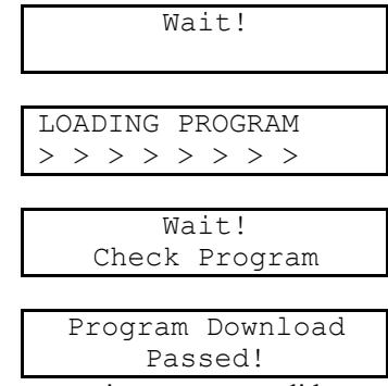
The new settings are now valid.
3.13—Command 78: Set time
Use Command 78 to set the time on the input panel.
Enter: 7 8 *
The LCD now asks for your ID and PIN:
Enter: Your ID number (1 or 2 digits)
     ID #:
     PIN 3:
# Your PIN code (6, 7, or 8 digits) #
Enter: The new time in hh:mm format. (Use
  military time.)
  #
Enter New Time
     hh:mm
Press: # to return to the time/date display.
3.14—Command 79: Set Winter/Summer mode
IMPORTANT! Command 79 is not available if the "Auto" selection was selected when programming with the PC software.
Use Command 79 to set the time to Standard time (Winter mode) or Daylight Savings time (Summer mode).
When you set the time, you're asked to choose between "Sunday" and "today." The time change always takes place at 2:00 a.m. If you choose "Sunday," the change will take place the following Sunday at 2:00 a.m. If you choose "today," the change takes place at 2:00 a.m. in the next twenty-four hour period.
Enter: 7 9 *
The LCD now asks for your ID and PIN:
ID #:
PIN #:
Enter: Your ID number (1 or 2 digits) # Your PIN code (6, 7, or 8 digits) #
CHANGE SUMMER ?
* OR #
Enter: * to cancel the request
# to continue with the change request
The LCD display asks whether you want to change the time on Sunday or Today within the next twenty-four hour period and changes at 2:00 a.m.
1–CHANGE SUNDAY
2-CHANGE TODAY
Enter: 1 to change on Sunday
2 to change today
#
The selection is confirmed:
CHANGE SUNDAY
 PROGRAMMED
Press : # to return to the time/date display
3.15—Command 86: Save the lock settings to the Touch Memory Key
Use Command 86 to save the lock settings on the lock to the Touch Memory Key. Use the red Touch Memory key.
IMPORTANT! No PIN codes are recorded.
Enter: 8 6 *
The LCD now asks for your ID and PIN:
ID #:
PIN #:
Enter: Your ID number (1 or 2 digits) # Your PIN code (6, 7, or 8 digits) #
Put Touch Memory
  on Side Port
Hold the green Touch Memory Key against side port.
LOADING PROGRAM
> > > > > > > >
When the LCD returns to normal display, the lock settings have been loaded onto the Touch Memory Key. They can be uploaded into your computer software.
4. Programmable Functions (Must use PC Software)
4.1—Single or Multiple Lock Modes
The input panel can be set to control one or two locks, using the same keypad. For example, you may have a separate compartment within a safe. Some PINs may be authorized to open only the outer lock, while manager PINs are authorized to open both. This setting is performed in the PC software.
You have two options for configuring this setting:
Option A One outer door and one inner door. This is the factory default. In this mode, if the user is allowed in the inner door and selects the inner door to open, the outer door opens automatically.
If the user selects the outer door to open, only the outer lock opens.
If the outer door is in a time locked control, neither door opens.
Option B Two independent doors.
4.2—Time Delay
You can program the time delay period from 0 to 99 minutes, in one-minute increments. The opening window can be programmed for 1 to 9 minutes. If the input panel controls two locks, you can set the time delay and opening window periods independently for each lock. The time delay countdown begins
immediately when you enter a valid PIN. When the time delay period is complete, the opening window period begins. You can cancel the time delay after it has started by pressing the [ key twice. After canceling, you or another user must enter a valid PIN to begin the time delay period again.
This setting is performed in the PC software.
5. Configuring the Lock Access Type
The lock may be configured as either single user, dual control, or Manager/Employee. These settings are performed using the PC software.
- Single User —A single valid PIN is all that is required to open the lock. If there is a time delay activated, a single valid PIN is required to start the time delay and then to open the lock during the opening window.
- Dual Control —Two valid PINs are required to make any programming changes or to open the lock. These may be either user or manager PINs. The second PIN must be entered within 60 seconds after entry of the first PIN. If there is time delay, only one PIN is required to start the time delay, but both PINs must be entered during the opening window to open the lock . Dual Control mode can also make use of the remote control option: the remote input can be one of the two PINs required to open the lock.
- Manager/Employee —This configuration allows entry of a valid PIN to enable or disable all user PINs. Two Modes are available:
Mode 1 allows a manager (IDs 01 and 02) to enable and disable user PINs.
Mode 2 allows a manager to enable and disable PINs and any valid user (03-20) to also disable user PINs. Only managers can enable PINs. This mode is useful if no manager is available at the end of the day to disable user codes.
5.1—Touch Memory Required with PIN
You can configure the lock to require use of a Touch Memory Key in conjunction with specific IDs. With this feature, when certain user PINs are entered, the user is prompted to press the Touch Memory Key to the touch panel on the left side of the input panel. The user must do this within 60 seconds after entering the PIN to open the lock. Refer to the computer software Programming and Operations Guide , Part Number 630-530.
6. Touch Memory Keys
The Touch Memory Keys allow you to transfer information back and forth between the lock and the computer, without a direct serial port connection. The general transfer capabilities are as follows:
- All programming settings and functions can be transferred from the computer to the lock via Touch Memory.
- In the case of multiple locks, you can use the programming stored in one Touch Memory Key to transfer programming to all locks.
- Most programming can be transferred from the lock to the computer. Exceptions are PINs, Time of Day, and the encryption key.
- The audit trail can be transferred from the lock to the computer.
- Programming and audit trails from only one lock at a time can be transferred to the Touch Memory Key. Downloading information from a second lock erases the existing data in the key.
There are four color-coded Touch Memory Keys you can use for different functions. The following table describes the capabilities and uses of each:
6.1—Touch Memory Key Functions
|
Key Color
(Name of Key) |
Function—When Used |
|---|---|
|
Yellow
(User Key) |
Touch Memory required with PIN. |
| Red | Transfer programming from the computer to the input panel, or |
| (Program Key) | retrieve existing settings from the input panel. |
| Blue | Store program changes and transfer them to multiple locks; transfer |
| (Program with Time Key) | new date/time settings |
| Green | Retrieve audit trail (event history) from the lock for uploading to the |
| (Audit Retrieval Key) | computer. |
|
Caution:
Loading any event history from a lock will erase any existing data from the key! |
Appendix
A.1—Changing the Clock Chip
The input panel clock operates on a battery-powered chip that stores some of the lock settings, including the Date/Time display and the audit trail. This data is retained in the chip memory even if power is disconnected. The battery has an estimated life of 30 years, but as a precaution, we recommend changing the battery after 10 years. You can enter the "Check Chip" command ( 6 2 * ) to check the age of the current battery. A warning displays on the LCD at the 10-year mark. When this warning displays, contact Sargent & Greenleaf, Inc. for information about having the battery changed.
A.2—Specifications for the Comptronic Model 6150
Input panel Components
The input panel consists of a cover and mounting bracket, which houses the keypad, LCD display, a 6-pin modular serial port jack, a Dallas Semiconductor Touch Memory port and the electronic circuit board. It is mounted on the outside of the safe. Input from the input panel is communicated to the Electronic Control Unit (ECU) mounted inside the safe. The input panel is connected to the ECU by a non-polarized cable with 6-pin RJ connector cable extending from the rear of the panel, through a .375-inch diameter hole in the safe.
| Input panel Dimensions | width 6.00 in. | 152 mm |
|---|---|---|
| length 6.00 in. | 152 mm | |
| height 1.37 in. | 38 mm |
Electronic Control Unit (ECU) Specifications
The ECU, which is the control unit for the lock system, consists of a single circuit board with a number of ports and connectors housed in a single unit. It is mounted inside the safe. The ECU is connected to the input panel via a cable with 6-pin RJ connector cable extending through a .375-inch diameter hole in the safe.
| Electronic Control Unit | width 4.75 in. | 121 mm |
|---|---|---|
| length 7.75 in. | 199 mm | |
| Dimensions | height 1.437 in. | 37 mm |
The ECU is connected via a 2-wire terminal block connector to an external AC/DC power supply by a 9 VDC line. The 9 volt signal is isolated to protect against ground loops and electrical attack methods on the lock. The lock can be opened by battery backup to the ECU in the event of a power failure.
| Lock Case Dimensions | width 2.39 in. | 61 mm |
|---|---|---|
| length 3.344 in. | 85 mm | |
| height 1.125 in. | 29 mm |
Touch Memory Port and Keys
The Touch Memory port on the input panel, and the Touch Memory reader attached to the serial port on the computer, are designed to transfer information to or from a Dallas Semiconductor Touch Memory Key. The Touch Memory Keys are color-coded and transfer the following types of information:
| yellow used in conjunction with PIN to open the lock |
|---|
|
red transfers programming from the computer to the ECU; retrieves
settings from the ECU |
|
blue transfers programming from the computer to multiple locks with
time/date settings |
| green retrieves audit trail from the lock |
"Lock Unlocked" Output
The "Lock Unlocked" output is an SPDT relay with contacts rated at a minimum of 1 amp at 24 volts. All 3 contacts of the relay should be connected to a terminal block or similar connector. The relay is energized when any of the locking devices are unlocked.
Duress Code Output
The Duress Code output is an SPDT relay with contacts rated at a maximum of 1 amp at 24 volts. All 3 contacts of the relay should be connected to a terminal block or similar connector.
A.3—Power Supply Requirements
Power supplies are available for either 110-120 VAC or 220-240 VAC, at a frequency of 50-60 Hz. The output is 9 VDC@1.5 amps. Use only approved power supplies with an output of 9VDC.
In areas where power shortages are common, a battery-backed DC power supply is available. This can supply hours of operation in the absence of AC main power.
The 9-volt battery unit is connected to the data port by an emergency power cable. This provides temporary power for a limited number of openings in the event of a power failure. Battery power is an emergency capability only, for use when there is an interruption to the normal power supply. The lock is not designed to run exclusively off battery power.
A.4—ID Position Worksheet
Use worksheet to identify who occupies which ID position and whether a PIN code has been set.
| ID Position | Description |
User
Name |
Code Set
Yes/No |
|---|---|---|---|
| 00 | Programmer | ||
| 01 | Manager | ||
| 02 | Manager | ||
| 03 | User | ||
| 04 | User | ||
| 05 | User | ||
| 06 | User | ||
| 07 | User | ||
| 08 | User | ||
| 09 | User | ||
| 10 | User | ||
| 11 | User | ||
| 12 | User | ||
| 13 | User | ||
| 14 | User | ||
| 15 | User | ||
| 16 | User | ||
| 17 | User | ||
| 18 | User | ||
| 19 | User | ||
| 20 | User |
Warranty
Comptronic Model 6150 Electronic Safe Lock Limited Warranty
Seller warrants that for two (2) years from the date of shipment from Seller's point of manufacture, the goods will be free from defects in material and workmanship, provided the goods are normally and properly used according to the Seller's written instructions.
THIS WARRANTY IS EXPRESSLY MADE IN LIEU OF ANY AND ALL OTHER WARRANTIES, EXPRESS OR IMPLIED. S & G DOES NOT WARRANT THAT THE GOODS ARE MERCHANTABLE OR FIT FOR ANY PARTICULAR PURPOSE EXCEPT AS EXPRESSLY PROVIDED HEREIN.
Seller's entire liability and Buyer's exclusive remedy in the event that the goods do not conform to the foregoing warranty shall be Seller's repair or replacement of the goods (including payment of freight costs to and from point of manufacture). This warranty does not apply to batteries or damage from battery leakage.
SELLER SHALL HAVE NO LIABILITY FOR ANY CONSEQUENTIAL, INCIDENTAL, INDIRECT OR SPECIAL DAMAGES. SELLER DOES NOT WARRANT ITS LOCK PRODUCTS TO BE IMPERVIOUS TO FORCIBLE OR SURREPTITIOUS ENTRY, AND SELLER SHALL HAVE NO LIABILITY FOR DAMAGE TO OR LOSS OF PROPERTY SOUGHT TO BE PROTECTED BY ANY SUCH LOCK.
S&G Confidential
The information contained in this document is proprietary to Sargent & Greenleaf, Inc. Publication or duplication of this copyrighted document is strictly prohibited.
Sargent & Greenleaf, Inc.
One Security Drive Nicholasville, KY 40356 USA 1-800-826-7652 Fax 1-800-634-4843 Outside the United States Tel. 859-885-9411 Fax 859-887-2057 ON THE INTERNET Email: sales@sglocks.com Website: http://www.sglocks.com
Corporate Headquarters European Headquarters
9 Chemin du Croset 1024 Ecublens Switzerland Tel. 41-21-691-9583 Fax 41-21-691-5349