Sargent & Greenleaf Electronic Safe Lock Series S&G Comptronic 6128 Installation
Open the original PDF document
View PDFComptronic™ 6128 Motorized Electronic Combination Lock
Installation Instructions
This Sargent & Greenleaf 6100 series electronic lock combines ease of operation with security. Advanced electronic circuit design makes it easy to install, easy to open, and easy to change codes. Follow these instructions carefully to get the best possible performance from your lock.
MOUNTING CONSIDERATIONS
- Sargent & Greenleaf 6100 series Motorized Electronic Combination Locks have been designed to use the same mounting screw locations and occupy the same space as a standard S&G 6730 mechanical lock. The 6100 series uses standard mounting dimensions to simplify retrofit in existing safes.
- The keypad diameter is 4 inches (101.6mm). This is slightly greater than the diameter of standard S&G dial rings for mechanical locks. The 61KP series keypad will cover any scratches or paint blemishes left by the old lock.
- Modifications to the lock (including lock bolt attachments) are not recommended, and will void the manufacturer's warranty.
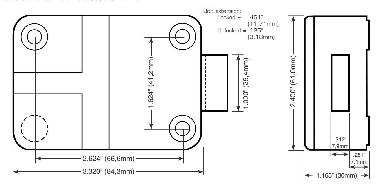
- A minimum distance of .150" (3.8mm) is required between the end of the lock case containing the bolt and the safe's blocking bar or cam plate which is normally blocked by the extended lock bolt. This is because the lock bolt may not be retracted quite as far by older batteries as by fresh ones.
- You should install fresh alkaline batteries in the keypad and connect the lock wiring cable to check the functions of the lock prior to installation.
- Do not allow the safe's blocking bar or cam plate to depress the electronic lock's bolt farther than it retracts during normal motor operation. This can lead to inconsistent lock operation.
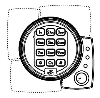
- The 6128 is normally installed with the keypad extension base to allow use of the lock's sophisticated security features. However, it can be installed without the keypad extension when these features are not required or will be utilized at a later date.
Sargent & Greenleaf, Inc.
One Security Drive, Nicholasville, Kentucky 40356 Phone (859) 885-9411 FAX (859) 887-2057

Sargent & Greenleaf S.A.
9, chemin du Croset, 1024 Ecublens, Switzerland Phone 41-21-691-9583 FAX 41-21-691-5349
INSTALLATION NOTES . . .
Although the model 6100 series is easy to install, we recommend the following procedures be performed only by an experienced locksmith or safe technician. Your safe may incorporate relocking devices that are attached to the combination lock. Misalignment or detachment of these devices can result in a lockout—a condition where the safe cannot be opened without damage.
ADDITIONAL ITEMS YOU WILL NEED . . .
The 6100 series requires two 9-volt alkaline batteries (not included). We recommend fresh Duracell® batteries. Do not use old or partially drained batteries in your lock.
Many installations can be performed with nothing more that a medium phillips screwdriver. If the manufacturer of your safe has made external relock device attachments to the lock, specialized tools and knowledge may be required.
INSTALLATION . . .
Step 1
Remove the existing lock (if present). The mounting plate should be smooth and flat, with 1 ⁄4 -20 (M6) mounting screw holes. The wire channel (spindle hole) must have a diameter of at least 5 ⁄16 inch (8mm).
6100 series locks can be mounted right-hand, left-hand, vertical-up, or vertical-down without any modifications or adjustments.
Step 2
Use a reamer or round file to remove any sharp edges from the wire channel (spindle hole) that might damage the wire cable.
Run both connectors through the wire channel. Gently pull the connectors and all excess cable to the outside of the safe. Make sure the cables are not crimped or stressed at any point.
Once you've made sure the wire cables are not crimped or in contact with any sharp surface, attach the lock to the safe's mounting plate. Use the 1 ⁄4 -20 (or metric M6) screws provided. Tighten securely so the lock is attached firmly to the plate.
The lock incorporates a bolt-through cover that allows mounting with the cover in place. Removing the cover voids the product warranty.
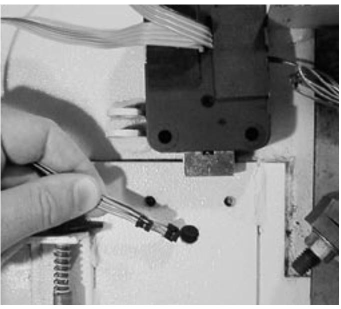
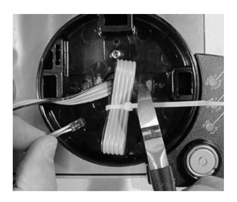
Note the coiled two-conductor cable that exits the side of the lock case. This is a closed circuit that may be used in certain applications where switches or other devices need to signal the lock that the boltwork is thrown or the door is closed. In many applications, it is not used. In these cases, do not cut the wire, but secure the coil in an area where it will not interfere with moving boltwork components (see photograph in step 4).
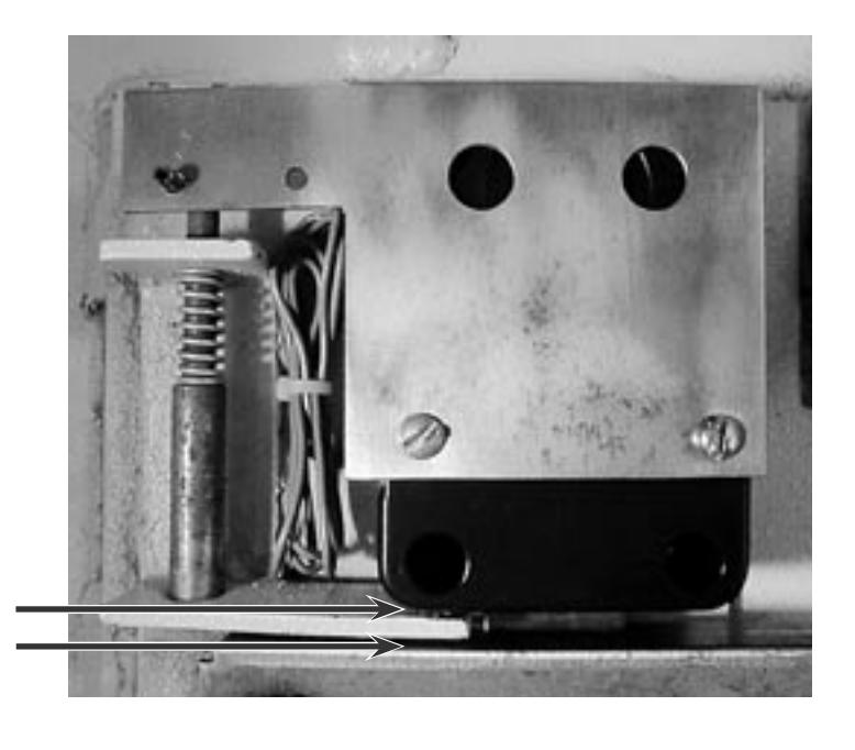
Step 4 (FOR SAFES WITH RELOCK DEVICES)
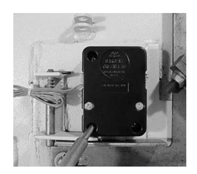
This installation requires attachment of the safe manufacturer's relock device plate to the lock cover using the cover screws. If your situation is similar, be sure the thickness of the relock device plate(s) is not great enough to prevent the screws from engaging the lock case by at least four threads. If necessary, use longer 8-32 (M4) machine screws to insure proper fit.
The photo also illustrates a required space of at least .150" (3,8 mm) between the end of the lock body and the blocking bar of the safe's boltwork.
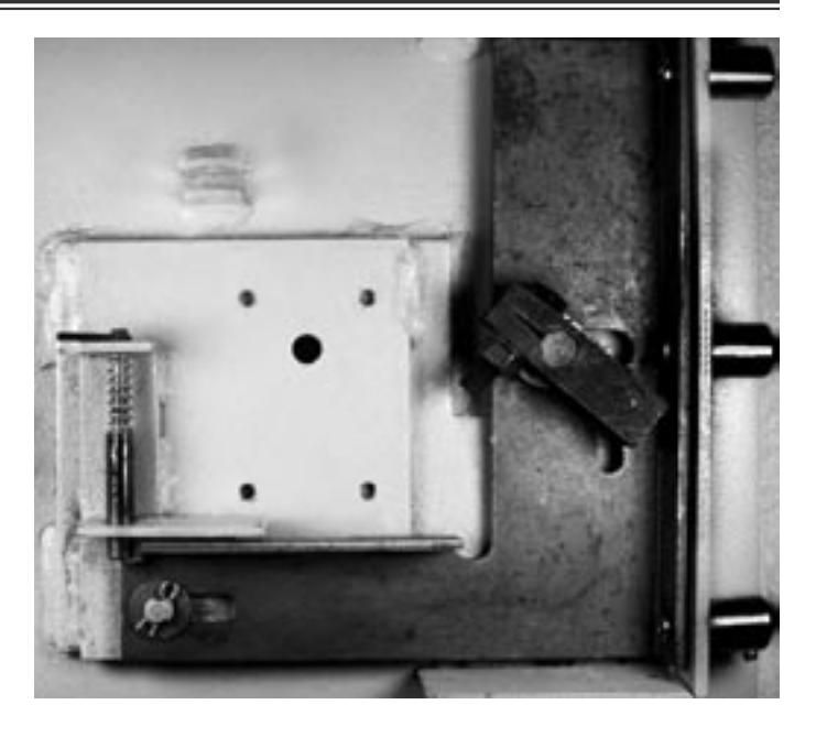
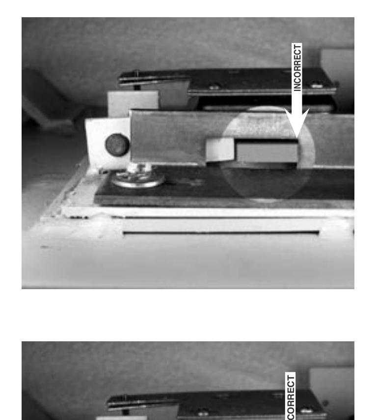
Make sure that the lock bolt does not bind against the safe's boltwork. 6100 series locks are sensitive to bolt end and side pressure. The safe's blocking bar or cam must not depress the lock's bolt far ther than it retracts under normal motor operation. Check to make sure this doesn't happen when the safe handle is moved to retract the door bolts (unlock the safe).
This photograph shows boltwork in the locked position which places pressure on the side of the lock bolt. This could prevent the lock from opening properly.
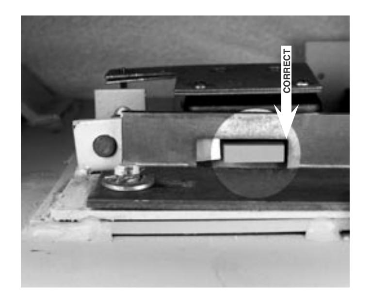
Step 6
The boltwork bind has been relieved by removing a small amount of material from the right side of the boltwork opening. When the safe's boltwork is fully thrown to the locked position, there is an air space on all sides of the electronic lock's bolt.
Step 7
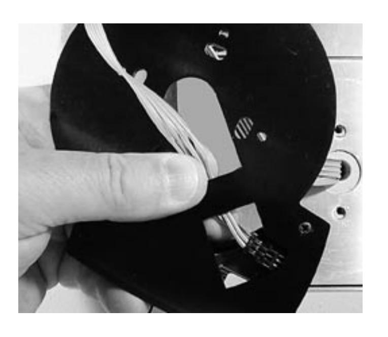
The lock's two cables use distinctly different connectors. Upon inspection, you will easily be able to determine which one plugs into the keypad and which one plugs into the keypad extension.
Run the appropriate connector and wire cable through the center hole of the keypad extension, and route it as shown. Plug the connector into its receptacle in the exten sion. Before placing the extension against the safe door, be sure to pull all excess cable through to the front of the extension.
Place the keypad base over the extension, and pull both cables through the base's center opening.
The extension can be positioned in any of four possible orientations (see below) to prevent interference with the safe handle or other door hardware. Use the two 8-32 (or M4) screws provided to attach the keypad base (and the extension underneath it) to the front of the safe.
Excess extension cable should be neatly folded and secured with a wire tie.
Step 9
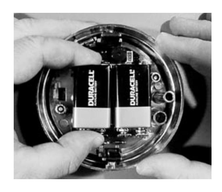
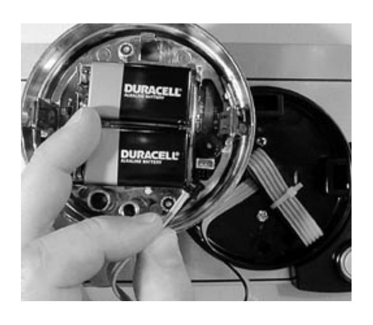
Install a new 9-volt alkaline battery in each of the keypad's battery holders (Duracell® is recommended). Support the top of each holder as the battery is inserted. This will prevent bending or breaking the holder.

The keypad cable connector is shaped so that it will fit into the circuit board receptacle only when aligned correctly. Insert the connector into its receptacle in the keypad housing. If it does not slide easily into place, do not force it . This means you need to turn it 180º before attempting to insert it again. When the lock cable connector is plugged into the keypad, the keypad will not work (no sound or LED flash when keys are pressed) until the keypad is installed into the base following steps 11 and 12.
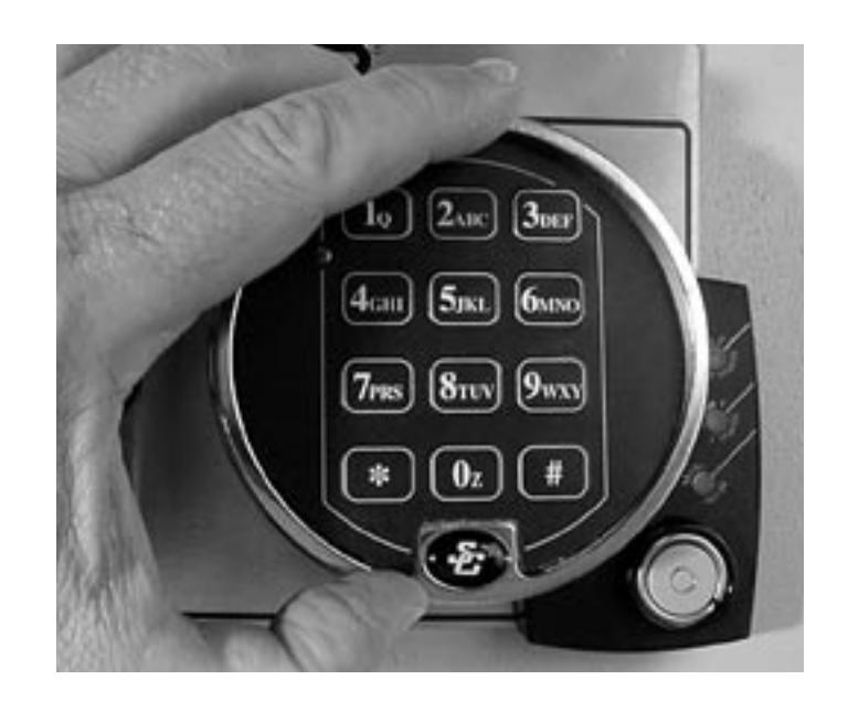
Place the keypad over the base. Make sure the wire cables are clear of the two spring clips, then push the keypad firmly onto the base. It should snap into place.
Note: To remove the keypad, pull the bottom (area nearest the S&G logo) away from the mounting base first.
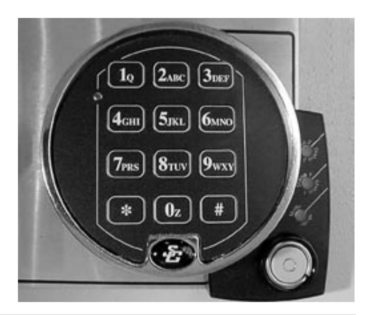
Step 12
The installation is complete. Refer to your lock's Operating Instructions for opening, code changing, time delay, and battery changing instructions. You will need to reset the tamper indication before the lock will operate. See the operating instructions for the required procedure.
MAKE SURE YOUR LOCK IS FULLY OPERA-TIONAL BEFORE CLOSING THE SAFE DOOR FOR THE FIRST TIME.
IMPORTANT DIMENSIONS . . .