Sargent & Greenleaf Electronic Safe Lock Series S&G 6150 Software Operation
Open the original PDF document
View PDFComptronic Model 6150 Safe Lock PC Software Programming and Operations Guide
Table of Contents
| 1. General Information | 3 |
|---|---|
| 1.1—Your Locking System Hardware Components | |
| 1.2—Power supply | 3 |
| 1.3—In Case of Power Failure | 3 |
| 2. PC Requirements and Software Installation | 4 |
| 2.1—PC Requirements | |
| 2.2—Installing the Software. | |
| 2.3—Test COM Port Configuration | |
| 2.3.1—Troubleshooting. | |
| C | |
| 3. Programming the System | |
| 3.1—Programming from the Computer | 6 |
| 4. Main Tab Features | 7 |
| 4.1—Serial Number. | 7 |
| 4.2—Configuring the Lock Type Access Mode | 7 |
| 4.3—Long Close (programmed at the input panel only | 8 |
| 4.4—Short Close (programmed at the input panel only) | 8 |
| 4.5—Keypad Tamper Alarm | 8 |
| 4.6—Duress Feature (must be activated by connecting to an alarm system) | |
| 4.7—Number of Installed Locks | |
| 4.8—PIN Digits | |
| 4.9—Changing between Standard Time and Daylight Savings Time | |
| 4.10—Remote Controll Settings. | |
| 4.11—Transfer. | |
| 4.12—File | |
| 4.13—Text View | 10 |
| 5. Users Tab Features | 11 |
| 5.1—Changing, Adding, and Deleting PINs | |
| 5.2—Doors Accessible | |
| 5.3—"Special" Features | |
| 5.4—Touch Memory Key Required with PIN | 12 |
| 6. Locks Tab Features | 13 |
| 6.1—High Force (Push-Pull) - Not Currently Available | |
| 6.2—Time Delay | |
| 6.3—Open Window. | |
| 6.4—Bolt Retraction | |
| 7. Doors Tab Feature | |
| 7.1—Door Configuration | 14 |
| 8. Timelock Tab Feature | 15 |
| 8.1—Timelock | |
| 9. Holidays Tab Features | |
| 9.1—Holiday Closing | 1/ |
| 10. Display Tab Features | |
|---|---|
| 10.1—Time Delay Display | |
| 10.2—Open Window Display | |
| 10.3—Beeper Enabled | |
| 10.4—Language on Lock's LCD | |
| 10.5—Setting the Time of Day and Date | |
| 11. Privileges Tab Features | 19 |
| 12. Lock Info Tab Features | 20 |
| 12.1—Encryption for Touch Memory Key | |
| 12.2—Lock Info (Only Stored in Lock File) | |
| 13. Touch Memory Keys | 21 |
| 13.1—Touch Memory Key Functions | |
| 14. Transferring Information | 21 |
| 14.1—Audit Trail | |
| 14.2—Accessing the Audit Trail from the PC | 22 |
| 14.3—Uploading the Audit Trail from the Lock | |
| 14.4—Download the Audit Trail from Input Panel | |
| 15. Operating the Lock | 24 |
| 15.1—User IDs and PIN Codes | |
| 15.2—Operating the Lock from the Input Panel | |
| 15.3—"Penalty Time" Lockout Features | |
| Appendix | 27 |
| A.1—Changing the Clock Chip | |
| A.2—Specifications for the Comptronic Model 6150 | |
| A.3—Power Supply Requirements | |
| A.4—IDPosition Worksheet | |
| Warranty | 30 |
1. General Information
1.1— Your Locking System Hardware Components
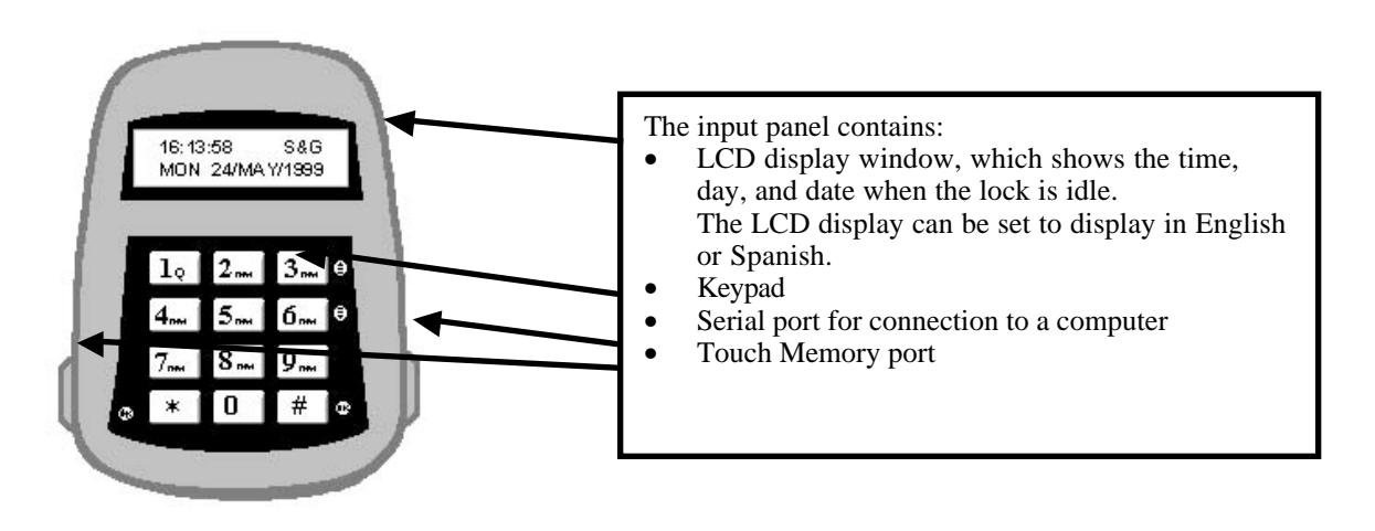
The Model 6150 Electronic Lock system has several components:
- An Input panel. The input panel contains a keypad and an LCD display window. It controls one or two separate locks. The input panel has a serial port for direct connection to a computer, and a Touch Memory® port for use in transferring information between the input panel and the computer by means of a Touch Memory Key.
- One or two electro-mechanical safe locks.
- An Electronic Control Unit, or ECU, which is secured inside the safe.
- An external DC power supply, which provides power both to the input panel and to the drive motor for the lock.
1.2—Power Supply
A DC transformer connected to an external power supply powers the Model 6150 Electronic Control Unit (ECU). The ECU provides power to the input panel and to the locks. The ECU stores programming information, including PINs, in non-volatile memory. The programming will not be affected by an interruption of power to the unit.
1.3—In Case of Power Failure
Input panel
In the event of a power failure, the lock(s) will remain locked. Power must be restored before it can be opened. When power is initially restored, the lock will be in the locked state, regardless of its status at the time power was lost. The lock cannot be opened inadvertently as a result of power outage or interruption.
An emergency battery cable is available, (Part No. 6151-037-000) which uses two 9-Volt alkaline batteries to open the lock a limited number of times. Do not use the emergency battery cable for normal operations.
2. PC Requirements and Software Installation
This guide is for reference using the 6150 PC Software, for programming user and lock functions.
2.1—PC Requirements
© Sargent & Greenleaf, Inc. 630-530 Org. 2/00
- ÿ Software must be installed on a system using Windows 95/98.
- ÿ Minimum: 486 DX2 66MHz, 16MB RAM, 5MB of available hard disk space. Recommended: Pentium 120, 32MB RAM, 5MB of available hard disk space.
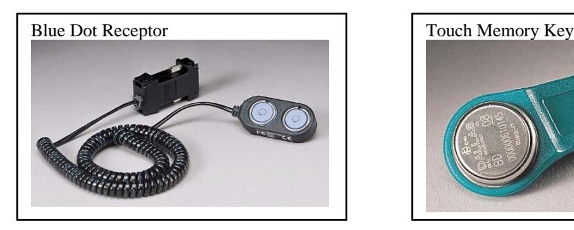
- ÿ One available serial port. (Serial port is required to use the Dallas Semiconductor Blue Dot Receptor for the Touch Memory Keys) Two serial ports are required if both the receptor and direct connections will be used.
2.2— Installing the Software
Before you begin, close any other programs currently running on your PC.
- 1. Insert the CD or floppy disk into the appropriate drive.
- 2. From the Start menu select Settings , and click on Control Panel
- 3. Double Click on the Add/Remove Software icon.
- 4. Follow the Windows step-by-step installation instructions until software is installed.
Touch Memory is a registered trademark of Dallas Semiconductor
2.3 — Test COM Port Configuration
In order for the software to communicate with the Touch Memory Key through the Blue Dot Receptor, or directly with the 6150 through the Direct Connect cable the COM port must be configured properly. To test the COM port communication, connect the receptor to the serial port, start the 6150 Programmer software and follow these steps:
1. Click on Configuration menu. The following dialog box should appear:
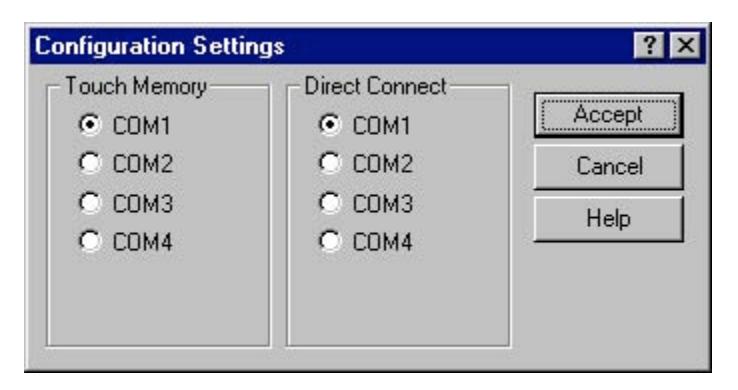
- 2. Select Com1 for the Touch Memory and click on ACCEPT.
- 3. Select the button.
- 4. Click on the button.
- 5. This will bring up the Program Transfer window.
- 6. Enter a random 6-digit number into the Lock Serial Numbers window. (e.g. 123456), and click the Add button.
- 7. Place either the program or audit trail Touch Memory Key in the Blue Dot Receptor.
- 8. Click on the button again to begin transfer.
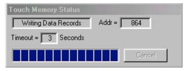
- 9. The PC software will attempt to communicate with the Touch Memory Key. If the selected COM port is correct you will get the Touch Memory Status window indicating the PC is reading the data on the key.
Note: Once you confirm a COM port with Touch Memory Key and receptor, you can select this COM port for a direct connect cable. If you have two available COM ports and are going to use both the receptor and direct connect, continue test to identify both available ports.
10. If the communication attempt is unsuccessful, the following window will appear:
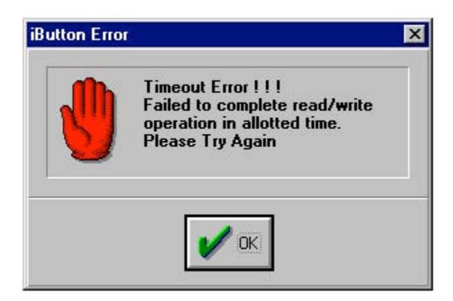
11. If the test fails, return to the Configuration Settings Dialog Box and select the next COM Port. Repeat the above steps for each Port until the communications attempt is successful.
2.3.1 Troubleshooting
If the software was not able to communicate with the Touch Memory Key on any of the ports check the cable connections and try again. If there is still no communication, there is likely a COM port conflict between the Blue Dot Receptor and another device connected to your computer (i.e. a modem). To resolve this conflict refer to your computer manual or the Windows Help file.
3. Programming the System
CAUTION! It is recommended all programming, testing, and employee training is conducted prior to uploading and activating the time lock schedule.
3.1—Programming from the Computer
You can perform all the programming functions for the lock at your computer terminal with the 6150 Programming Software. Programming from the computer is especially useful if you have multiple locks, because you can make changes to settings that would affect all locks, download the changes to the Touch Memory Key, and use the key to change the settings on all locks. You can also transfer changes to selected settings without overwriting all the other existing settings in the lock. For instance, if you need to change the time delay opening window for all locks throughout your business, you can use one Touch Memory Key to download just this change to all locks. All other settings will remain unchanged.
To program from the computer, first open the 6150 Programming software by clicking on Start , then Programs and then the program folder you installed the software in.
In the upper left corner of the window, click on the Settings Editor button:

The Settings Editor window Main tab is displayed. You can change information about the general settings on this tab—lock type, number of locks, number of digits required for each PIN, etc. Other tabs allow you to set or change information about Users and Privileges, Locks and Lock Information, Doors, the LCD Display, and Time Lock and Holiday locking information.
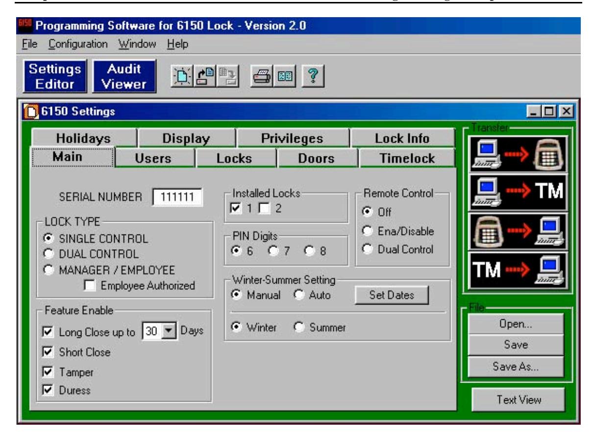
4. Main Tab Features
4.1– Serial Number
To distinguish between multiple 6150 units, a different serial number should be assigned to each. The number can be up to six (6) characters, and is used in the encryption process. The factory default value is 1 1 1 1 1 1 and is only changeable by using the PC software.
4.2– Configuring the Lock Type Access Mode
The lock may be configured as single user, dual control, or Manager/Employee. To activate, click circle.
- Single User —A single valid PIN is all that is required to open the lock. If there is a time delay activated, a single valid PIN is required to start the time delay and then to open the lock during the opening window.
- Dual Control —Two valid PINs are required to make any programming changes or to open the lock. These may be either user or manager PINs. The second PIN must be entered within 60 seconds after entry of the first PIN. If there is time delay, only one PIN is required to start the time delay, but both PINs must be entered during the opening window to open the lock . Dual Control mode can also make use of the remote control option: the remote input could be one of the two PINs required to open the lock.
- Manager/Employee —This configuration allows entry of a valid PIN to enable or disable all user PINs. Two Modes are available:
Mode 1 Click on the circle for Manger/Employee. This allows a manager (IDs 01 and 02) to enable and disable user PINs.
Mode 2 Click on both the Manager/Employee circle and check the box for employee authorized. This allows a manager to enable and disable PINs and any valid user (03- 20) to also disable user PINs. Only managers can enable PINs. This mode is useful if no manager is available at the end of the day to disable user codes.
4.3—Long close (programmed at the input panel only)
A factory default setting is notated by a check mark 3 in the box, meaning the feature is enabled. To disable the feature, simply click on the box to remove the check mark 3.
The long close allows you to override the regularly scheduled opening windows for periods of up to 99 days, without having to change the normal schedule. Use this feature for irregular, one-time events (i.e., during a company closing or holiday). To program the long close, enter at the input panel:
5 2* (PIN) #
You will be prompted to enter a starting date and time, then an ending date and time. When the long close period expires, the lock returns to the normal 7-day time lock schedule.
WARNING! Once set, THE LONG CLOSE CANNOT BE OVERRIDDEN . Be very certain you enter the correct values! You could lock yourself out.
4.4—Short Close (programmed at the input panel only)
A factory default setting is notated by a check mark 3 in the box, meaning the feature is enabled. To disable the feature, simply click on the box to remove the check mark 3.
The short close function allows you to close the lock for a specified short period of time. You can set the short close for 1 to 99 minutes, in one-minute increments. To set the short close, enter at the input panel:
7 2* (PIN) #
4.5—Keypad Tamper Alarm
A factory default setting is notated by a check mark 3 in the box, meaning the feature is enabled. To disable the feature, simply click on the box to remove the check mark 3.
When enabled, and an attempt is made to remove the housing from the input panel, a tamper-detect switch disables the lock putting it in a tamper alarm mode. When in tamper alarm, a manager PIN code is required to clear it and open the lock. Any other valid user codes will not work, and the LCD will flash TAMPER ALARM for 15 seconds.
To clear the alarm, enter the manager code once. The TAMPER ALARM message displays on the LCD. Re-enter the same manager code within 10 seconds to disable the tamper alarm and open the lock.
The tamper condition is recorded in the audit trail history.
4.6—Duress Feature (must be activated by connecting to an alarm system.)
A factory default setting is notated by a check mark 3 in the box, meaning the feature is enabled. To disable the feature, simply click on the box to remove the check mark 3.
When enabled, you can send a duress alarm to a monitoring center, by entering a user code that is one number higher or lower on the last number of the user's normal PIN Code and press the # key.
For example, if the normal user code is 1 2 3 4 5 6 for PIN position 02, the user can activate the duress alarm by entering 0 2 1 2 3 4 5 5 or 0 2 1 2 3 4 5 7, followed by #. If the user code ends in 0, use 1 or 9 to activate the duress alarm.
All PIN codes can send the duress signal at any time. It can also be sent during programming sequences.
4.7—Number of Installed Locks
The input panel can be set to control one or two locks, using the same keypad. For example, you may have a separate compartment within a safe. Some PINs may be authorized to open only the outer lock, while manager PINs are authorized to open both.
A check mark 3 in the box indicates lock 1 or 2 are installed.
4.8—PIN Digits
You can select how many digits are used in the PIN codes. Choose 6, 7, or 8 and click on the appropriate circle to activate.
4.9—Winter – Summer Setting (Standard Time and Daylight Savings Time)
The computer program also allows you to decide whether to set the time change to happen automatically or to change it manually. If you select Manual you change the time at the input panel with Command 79. If you select Auto you need to click on the Set Dates button and enter the change over dates.
Once Manual or Auto are selected, choose the current time of year by selecting Winter (Standard Time) or Summer (Daylight Savings Time).
IMPORTANT! Command 79 is not available if the "Auto" selection was selected when programming with the PC software.
4.10—Remote Control Settings
The ECU allows for connection of a remote control signal (5 to 12 volt DC) from an alarm/monitoring security system.
- Off —Disables remote control.
- Ena/Disable —the Remote Control signal must be present for any lock functions to be enabled. In this mode, the lock cannot be opened or programmed without the Remote Control signal.
- Dual Control —valid only for a Dual User setting. In this mode, the remote control signal can replace one of the two required PINs. Two valid PINs can still operate the lock without the remote control signal in this configuration.
- Note: This mode is available only if your LOCK TYPE was set for DUAL CONTROL .
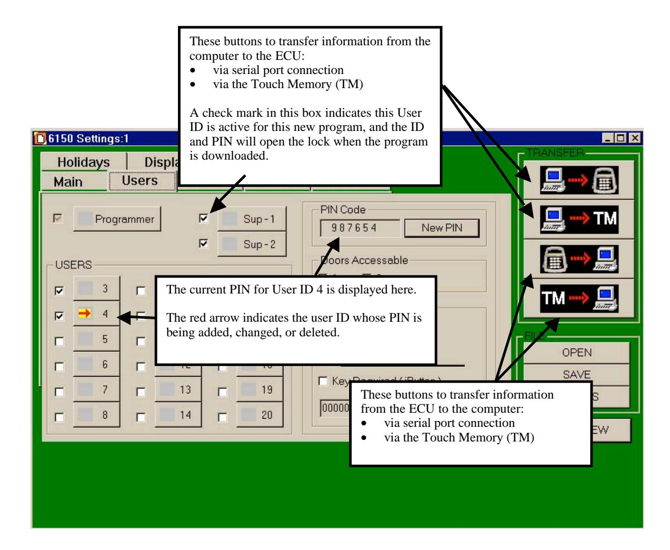
4.11—Transfer
This box and buttons remains constant on each of the different tab windows. You use these buttons to transfer data as indicated between PC and lock, PC and Touch Memory Key, lock and PC, and Touch Memory Key and PC.
4.12—File
This box and buttons remains constant on each of the different tab window. You use these Open, Save, and Save As buttons to manage your 6150 files.
4.13—Text View
This button remains constant on each of the different tab windows.
Click this button to see a standard text document listing of all settings you have made. This text document can be printed so you have a hard copy record.
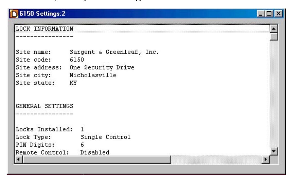
Caution: Safeguard any printed text version because it will contain IDs and the corresponding PIN code.
5. Users Tab Features
5.1—Changing, Adding, and Deleting PINs
To change a PIN, go to the Settings Editor window and click on the Users tab:
- Click on the user ID you want to set, change, or delete. The current PIN is displayed on the right side of the window.
- Click on New PIN to change it.
- You can also change other authorizations and settings for this PIN. These functions are discussed in later sections of this manual.
Note: Record which ID has been assigned a PIN Code and who the position belongs to, using the ID Position Worksheet, Section A-4, Page 29.
5.2—Doors Accessible
Click on the selected box to show which door the user has access to.
5.3—"Special" Features
Using the software program an ID position can be given three special access conditions. They are:
- 1. Time Delay Bypass—allowing them to access the lock without having to wait for the time delay.
- 2. Second PIN Required—this is a special dual control mode for a specified ID, requiring the ID position to have a second PIN entered before they can open the lock.
- 3. If both boxes are checked, then the Time Delay Bypass and Second PIN are active.
5.4—Touch Memory Key Required with PIN
You can configure the lock to require use of a Touch Memory Key in conjunction with specified PINs. With this feature, the user is prompted to press the Touch Memory Key to the touch panel on the left side of the keypad. The user must do this within 60 seconds after entering the PIN to open the lock. You can define some user PINs to require the Touch Memory Key, and other user PINs can be defined to open the lock without the key.
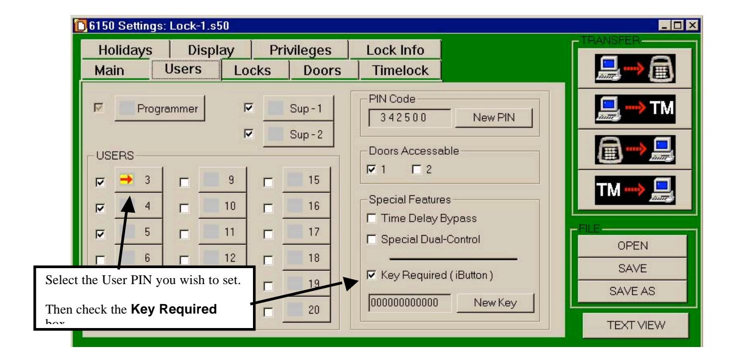
To set or change the Touch Memory Key requirement for a User ID:
- Select the user ID you wish to set or change. In the example, we've selected User ID 03. The PIN Code and other settings for this ID are displayed.
- To set the Touch Memory Key requirement, check the Key Required (iButton) box as shown. This user now must use the Touch Memory Key in conjunction with their PIN to open the lock. You can change this setting for User ID 03 by un-checking the box.
- You must transfer the setting to the yellow Touch Memory Key.
- Place the yellow Touch Memory Key in the Blue Dot Receptor connected to the PC.
- Click New Key button. The Touch Memory Status box will appear briefly on screen indicating the setting has been made.
6. Locks Tab Features
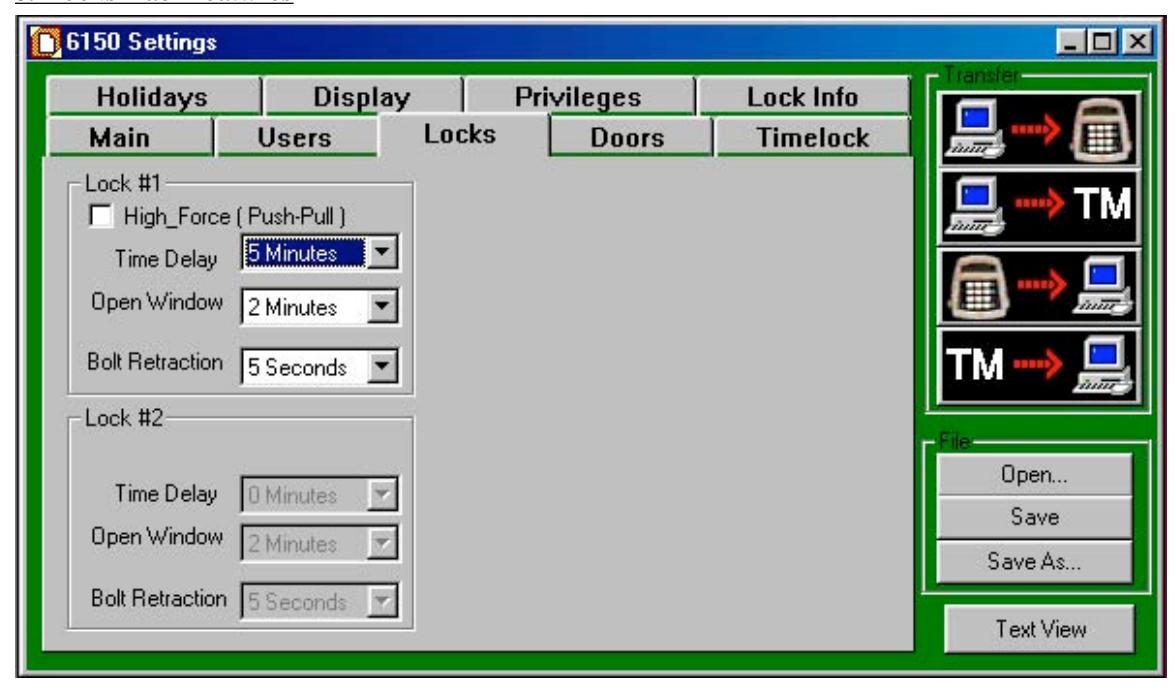
6.1—High Force (Push – Pull) – Not Currently Available
6.2—Time Delay
Select the number of minutes you want for time delay. You can program the time delay period from 1 to 99 minutes, in one-minute increments. If the input panel controls two locks, you can set the time delay and opening window periods independently for each lock. The time delay countdown begins immediately when you enter a valid PIN.
Lock #2 is only active if the Installed Locks box 2 is checked on the Main Tab window.
6.3—Open Window
Once time delay minutes are selected, the open window is available. The opening window can be programmed for 1 to 9 minutes.
6.4—Bolt Retraction
The 6150 lock bolt retracts and then extends to a lock position automatically. You can vary the amount of time, up to 60 seconds, of the bolt retraction to meet any operational needs. The factory default is 5 seconds.
7. Doors Tab Features
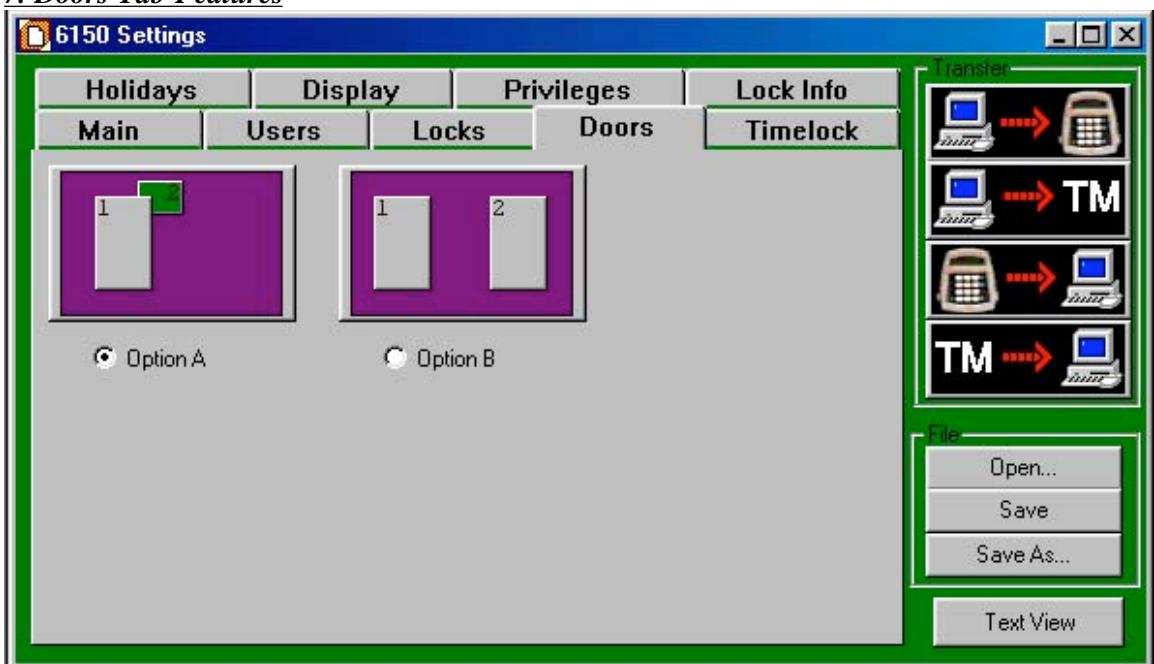
7.1—Door Configuration
Option A One outer door (1) and one inner (2) door. This is the factory default. In this mode, if the user is allowed in the inner door #2 and selects the inner door to open, the outer door #1 opens automatically.
If the user selects the outer door to open, only the outer lock opens.
If the outer door is in a time locked control, neither door opens.
Option B Two independent doors.
8. Timelock Tab Features
8.1—Timelock
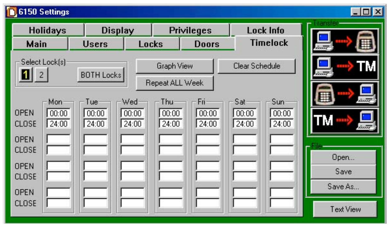
CAUTION! It is recommended all programming, testing, and employee training is conducted prior to uploading and activating the time lock schedule.
IMPORTANT! The programming of time lock periods is from the time the lock can be opened until the time it is to be locked.
The time lock feature disables the lock except during the time periods you specify. You set up the time lock schedule from the computer: on the Settings Editor window, click on the Timelock tab. You can program up to four opening/closing periods per day, and the time lock intervals can be different for each day of the week—for example, to allow for closing on Friday until opening on Monday. The time lock schedule you set up repeats on a rolling seven-day basis. You can set a different time lock schedule for each lock.
Note: If the inner door is opened while the outer door is in time lock, the time lock mode overrides the automatic opening of the outer door. You cannot access the inner door while the outer door is in time lock.
Although the programming software will not allow you to set up a combination of opening windows and time lock that would cause a permanent lockout, you should still be very careful when setting up the timelock schedule to make certain the lock can be accessed at critical times. The time lock cannot be bypassed or overridden under any circumstances.
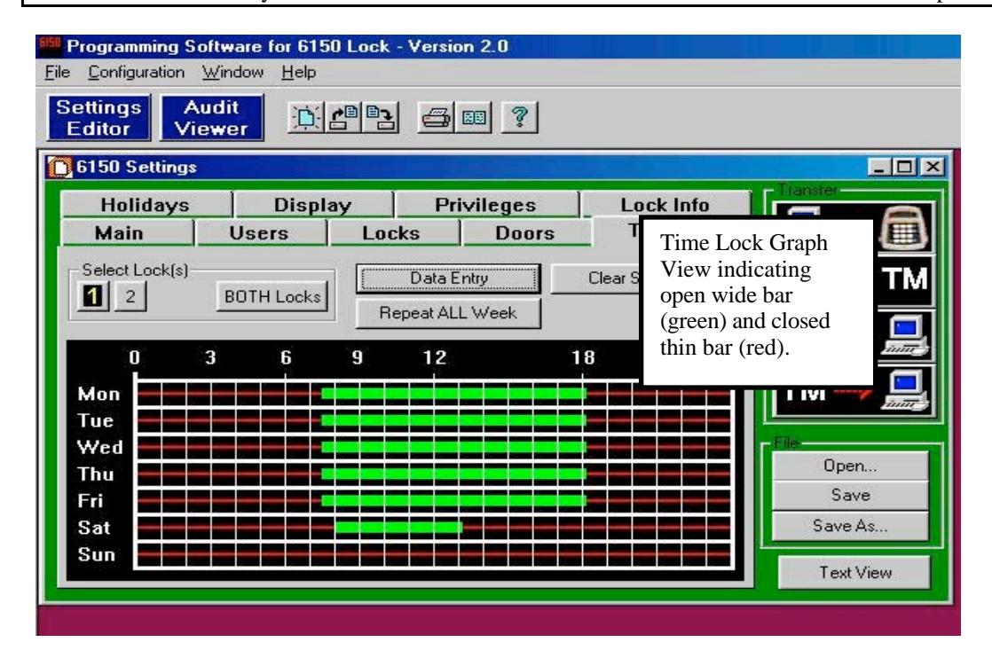
IMPORTANT! Confirm Time Lock Settings! It is recommended you click on the "Graph View" and look at the bar graph indicating the time periods you want the lock to be UNLOCKED for business. Unlocked is indicated by the GREEN wide bar. The thin RED line indicates closed or locked periods.
9. Holidays Tab Features
9.1—Holiday Closing
You can pre-program up to 20 holiday closing periods, which will override the time lock 7-day closing schedule.
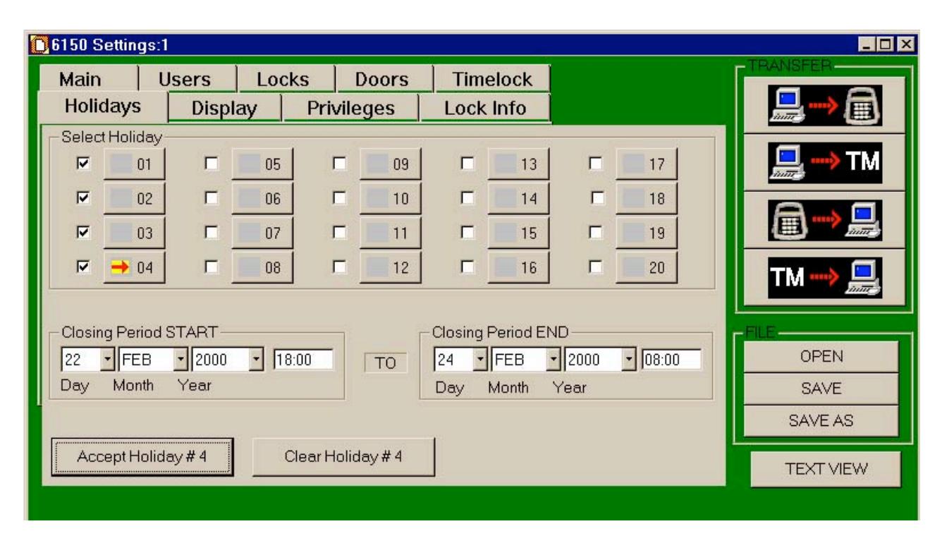
Select the holiday number, 01 through 20, you want to set. (In this example, we have set up Holiday 04 for President's Day.) Then enter the day, month, year, and time you want the holiday closing period to start and when you want it to end. When you have entered the closing period times correctly, click on Accept Holiday #_ to set the closing time. If you decide to change a holiday closing setting, you can clear it and re-enter it, only if the holiday lockout period has not already started .
10. Display Tab Features
10.1—Time Delay Display
This setting is for LCD on the Input panel. The factory default is for time delay minutes to be displayed and have the seconds count down to zero time remaining.
This setting may be changed to a count up of the time delay minutes, or be turned off so no time is indicated on the LCD.
10.2—Open Window Display
This setting is for LCD on the Input panel. The factory default is for opening window minutes to be displayed and have the seconds count down to zero time remaining.
This setting may be changed to a count up of the opening window minutes, or be turned off so no time is indicated on the LCD.
10.3—Beeper Enabled
The factory default setting is for a beep to occur every ten (10) seconds at the Input panel, during both the time delay and opening window timing counts.
Remove the check mark 3from the box to disable.
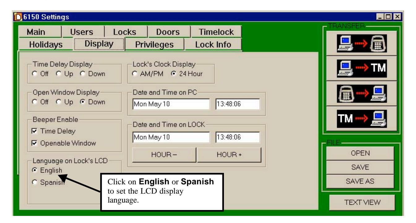
10.4—Language on Lock's LCD
The factory default is English. To change to Spanish, simply click on the circle.
10.5—Setting the Time of Day and Date
You can change or set the time of day displayed on the input panel LCD in three ways:
- At the input panel (Reference " Input Panel User Guide , Part No. 630-531)
- At the computer, via direct connection to the lock
- At the computer, downloaded to a Touch Memory Key and uploaded to the lock.
From this window, you can change many of the settings for the LCD display. Change the date and time by highlighting the appropriate field and typing in the correct entry. Or, if all you need to do is adjust the hour (e.g., for locks installed in another time zone), use the HOUR - and HOUR + buttons.
Note: You can also set whether the time displays in 24-hour mode (military time) or AM/PM. You can only change this setting with the computer program.
11. Privileges Tab Features
This Privilege tab provides a means for changing which Commands can be performed at the Input Panel as assigned to managers (shown as Supervisor #1 and #2 at bottom of window) and users. Reference Input Panel Guide, part number 630-531.
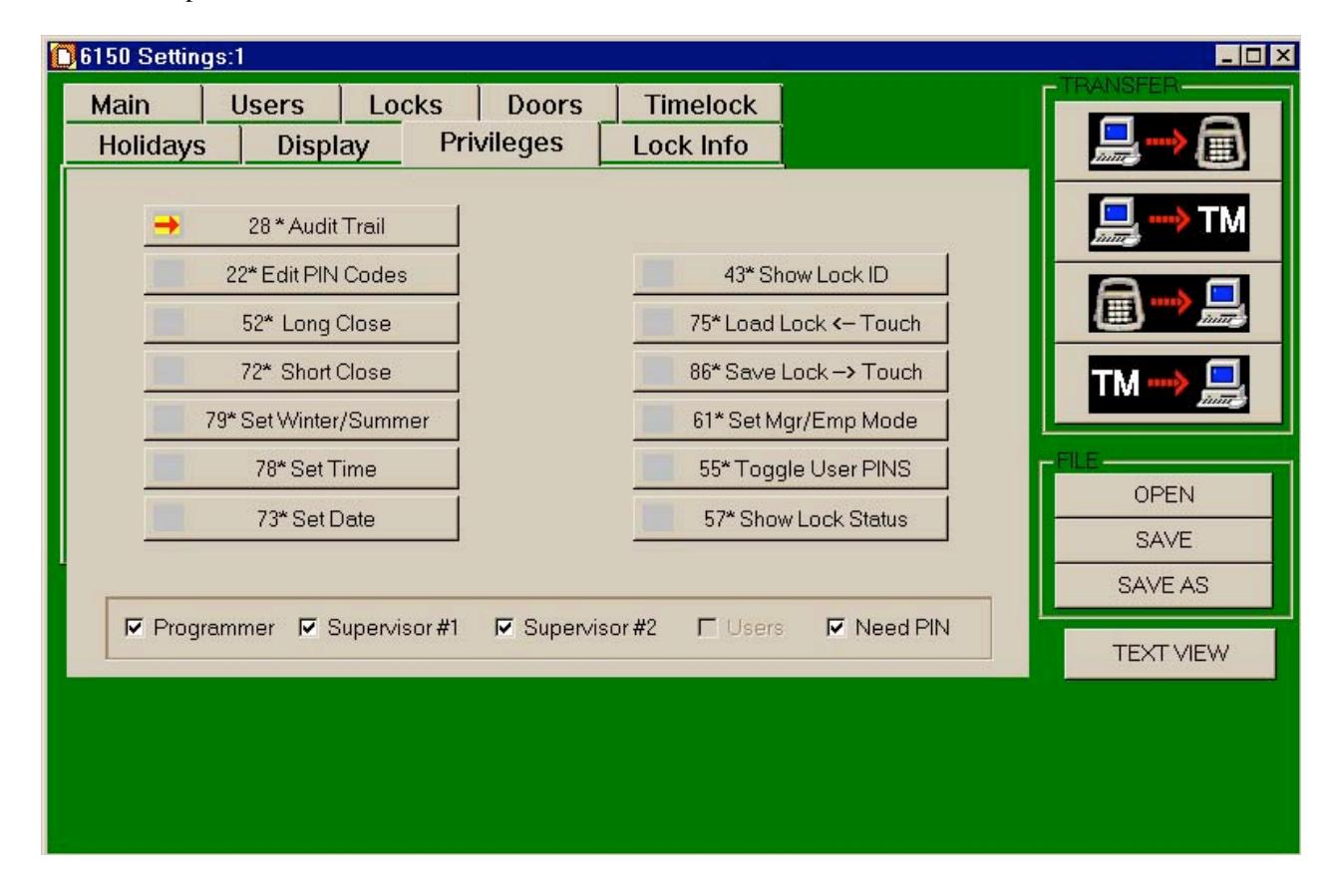
Click on a Command button, a red arrow will appear in the box at left of the command number, and a check mark will appear in the box next to the Programmer, Supervisor (Manager) #1, Supervisor (Manager) #2, or User indicating whether they have authorization to use the command at the Input Panel.
Removing the check mark from the programmer, manager (supervisor) or user boxes removes the authorization.
Go through each Command and select whether the programmer, manager (supervisor), or users may have authorization.
The Need PIN box should remained checked; this indicates an ID and PIN must be used with the Command.
12. Lock Info Tab Features
12.1—Encryption for Touch Memory Key
This is a security function that uses a sixteen (16) character identifier, which performs an encryption of data when transferred to a Touch Memory Key.
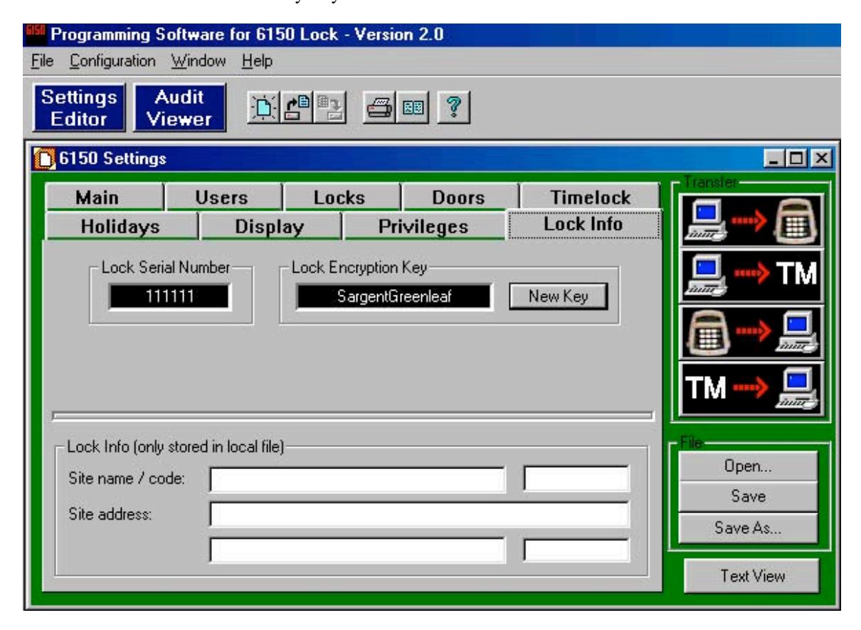
From the 6150 Settings window click on Lock Info tab, then click on the New Key button opening the iButton Security Code window.
At this window you can change the factory default identifier "Sargent Greenleaf" to your own.
12.2—Lock Info (Only Stored in Lock File)
Type in the site name and address of where the unit is in service. This information will appear on the Text View .
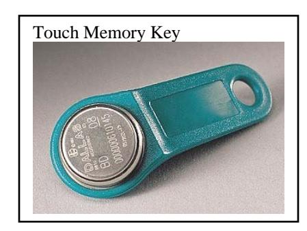
13. Touch Memory Keys
The Touch Memory Keys allow you to transfer information back and forth between the lock and the computer, without a direct serial port connection. The general transfer capabilities are as follows:
- All programming settings and functions can be transferred from the computer to the unit via Touch Memory.
- In the case of multiple units, you can use the programming stored in one Touch Memory Key to transfer programming to all 6150 systems.
- Most programming can be transferred from a unit to the computer. Exceptions are PINs, Time of Day, and the encryption key.
- The audit trail can be transferred from the unit to the computer.
- Programming and audit trails from only one lock at a time can be transferred to the Touch Memory Key. Downloading information from a second lock erases the existing data in the key.
13.1—Touch Memory Key Functions
There are four color-coded Touch Memory Keys you can use for different functions. The following table describes the capabilities and uses of each:
|
Key Color
(Name of Key) |
Function—When Used |
|---|---|
|
Yellow
(User Key) |
Touch Memory required with PIN. |
| Red | Transfer programming from the computer to the Input Panel, or |
| (Program Key) | retrieve existing settings from the Input Panel. |
| Blue | Store program changes and transfer them to multiple locks; transfer |
| (Program with Time Key) | new date/time settings |
| Green | Retrieve audit trail (event history) from the lock for uploading to the |
| (Audit Retrieval Key) | computer. |
|
Caution:
Loading any event history from a lock will erase any existing data from the key! |
14. Transferring Information
You can transfer information and the audit trail between the computer and the lock in two ways:
- Serial port connection from the computer to the user panel.
- The Touch Memory Key.
In addition to transferring programming information from the computer to the lock, you can also transfer information from the lock to the computer. The event history (audit trail) and all other information about the lock settings, except for PIN numbers, can be uploaded from the lock to the computer.
14.1—Audit Trail
The lock maintains an audit trail of the 500 most recent events. You can view the audit trail on the LCD display; download it to the computer via the Touch Memory Key or direct serial port connection. Because the audit trail is held in non-volatile memory, power outages or disconnections do not alter it. For each event, the audit trail records the following:
- Date
- Time
- ID
- Event Description
To keep the memory from filling up with multiple repetitions, consecutive repetitions of certain events (e.g., Startup and Tamper Alarm ) are not recorded. The audit trail also does not record actions attempted when the lock is in Penalty Time , although the start of the Penalty Time period itself is recorded.
14.2—Accessing the Audit Trail from the PC
To access the audit trail from the PC program, click on the Audit Viewer button:

The Audit Viewer window is displayed. To view the last uploaded audit trail, click on OPEN. The File window is displayed. Select the audit trail file for the lock you wish to view either by doubleclicking on it, or highlighting it and clicking on Open.
14.3—Uploading the Audit Trail from the Lock
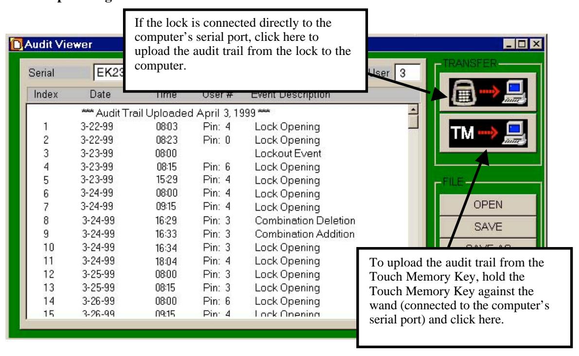
To upload a more recent audit trail, you can transfer data from the lock directly to the computer via the serial port connection. Click on the TRANSFER button (keypad to computer) at the upper right corner of the window.
If the lock is not connected directly to the computer, you can upload the audit trail from the lock to the Touch Memory Key. Then upload the data from the Touch Memory Key to the computer by pressing the Touch Memory Key against the Blue Dot Receptor (which must be attached to the computer by a serial port) and clicking on the second TRANSFER button (Touch Memory to computer; see below):
14.4—Download the Audit Trail from Input Panel
Use Command 28 to download the audit trail to a green Touch Memory Key.
Enter: 2 8 *
The LCD now asks for your ID and PIN:
ID #:
PIN #:
Enter: Your ID number (1 or 2 digits) # Your PIN code (6, 7, or 8 digits) #
The LCD displays the options available for the audit trail.
1-PRINT 2-TOUCH
3-DISPLAY AUDIT
Press: 2
The LCD instructs you to hold the Touch Memory Key on the side port.
Put Touch Memory
  on Side Port
Hold the green Touch Memory Key against side port.
Continue holding while the LCD displays the following message:
LOADING PROGRAM
> > > > > > > >
When the LCD returns to time/date display, the audit trail has been loaded onto the Touch Memory Key. It can now be uploaded into your computer software. Use the Audit Viewer window of the 6150 software to upload the audit trail.
The following table lists the audit trail messages when viewed at the input panel. An "X" in this table represents a variable number such as a lock number or a PIN code.
| LCD Display | Description of Event | ||
|---|---|---|---|
| START UP | System Power-up | ||
| TAMPER DETECT | Displays the time the tamper is initially detected and lockout occurs. | ||
| DURESS CODE | Displays the time the duress PIN is entered. | ||
| IN PENALTY | Displays the time the "In Penalty" period begins. | ||
| WRONG PIN | An invalid PIN was entered. | ||
| PIN ENTERED | Displays when the first of two PINs is entered in dual control mode. | ||
| DOOR CFG MOD | The door configuration parameter is changed. | ||
| AUDIT READ | Indicates that the Audit Trail has been read (in any manner: PC, LCD, | ||
| printer) | |||
| NEW HOUR/DATE | The date and time has been modified. | ||
| L CLS STARTED | Long Close started. | ||
| S CLS STARTED | Short Close started. | ||
| W/S CHG PASS | The Winter/Summer mode was successfully changed. | ||
| PC CONNECT | The lock was connected to the PC. | ||
| PC CHG PASS | The lock program was changed via the PC. | ||
| PC CHG FAIL | An attempt to change the lock program via the PC was denied. | ||
| PROG TO PC | Programming information was sent from the lock to the PC. | ||
| HOLIDAY CHG | The holiday calendar was changed. | ||
| PANEL LOST | Communication from the panel was lost. | ||
| PANEL FOUND | Communication to the panel was re-established. | ||
| LOCK TYPE CHG | The lock mode was changed (single, dual, manager/Employee) | ||
| TM CHG PASS | The lock program was changed via the Touch Memory Key. | ||
| TM CHG FAIL | An attempt to change the lock program via the Touch Memory Key was | ||
| denied. | |||
| TD X STARTED | The time delay on lock x was started. | ||
| LOCK X OPENED | Lock x was unlocked. | ||
| TIME DLY X CHG | The time delay on lock x was changed. | ||
| OPEN WIN X CHG | The Opening Window on lock x was changed. | ||
| TL X CHG | Any Time Lock parameter for lock x was changed. | ||
| PIN XX CHANGE | PIN code xx was changed, added, or deleted. | ||
| LOCK X SECURED | Lock x (1 or 2) has locked (extended its bolt) | ||
15. Operating the Lock
15.1—User IDs and PIN Codes
There are 21 user IDs, which identify the type of user, they are:
ID 00 is the programmer position
IDs 01 and 02 are manager positions
IDs 03-20 are individual user positions
Each user has an individual PIN code to access the lock. User PIN codes may be 6, 7, or 8 digits (characters), and are user changeable.
ID 00, the programmer code, can configure the lock and set up other user IDs, including manager codes; but cannot open any locks. The following table summarizes the privileges and capabilities of each PIN position.
Note: These privileges are set at the factory. You can change any of them with the computer program, using the programmer PIN (00).
|
Capabilities: Can this PIN Code
|
|||
|---|---|---|---|
| open the lock? | No | Yes | Yes |
| bypass the Time Delay? | No |
Programmable*
(see "Special" PIN Codes below) |
Programmable*
(see "Special" PIN Codes below) |
|
bypass time lock?
program the lock? |
No
Yes |
No
Limited |
No
No |
| modify their own PIN? | Yes | Yes | Yes |
| modify other users' PINs? | Yes (all) |
Yes (except the
Programmer ID) |
No |
| enable the short close? | Yes | Yes | No |
| enable the long close? | Yes | Yes | No |
| access the audit trail? | Yes | Yes | No |
15.2—Operating the Lock from the Input Panel
Note: Reference " Input Panel User Guide ", Part No. 30-531 for Input Panel Operations.
To open the lock from the input panel, you must enter your ID and PIN. The procedure is as follows:
- 1. Press the # key. The lock will beep once, and the LCD display will prompt you for your ID.
- 2. Enter your ID and press # to move the cursor to the next line.
- 3. Enter your PIN. Press # again. If there is only one lock, it will open. If there are two locks, the LCD will prompt you to select Lock 1 or Lock 2. The LCD displays which lock is opening: LOCK 1 or LOCK 2 .
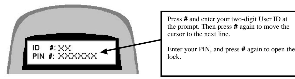
The LCD displays X s in place of the numbers you enter, for security. Each time you press a key, the input panel beeps once, and the cursor on the LCD screen moves to indicate your entry.
ENTRY ERRORS
If you make a mistake in your entry and press #, the lock beeps a series of short, fast beeps, and the following message is displayed.
INVALID PIN OR TOUCH MEMORY
Wait for the lock to clear (the date and time displays) and start your entry again.
You may also cancel an entry by pressing the * button, IF you haven't already pressed #.
15.3—"Penalty Time" Lockout Feature
If four (4) consecutive invalid PINs are entered, either to open or program the lock, the lock automatically goes into "penalty time" for 15 minutes. At the end of the penalty time, enter a valid PIN to open the lock. Any entry during penalty time has no effect on the lock or time.
Note: There is no way to bypass the 15-minute penalty time lockout.
Appendix
A.1—Changing the Clock Chip
The input panel clock operates on a battery-powered chip that stores some of the lock settings, including the Date/Time display and the audit trail. This data is retained in the chip memory even if power is disconnected. The battery has an estimated life of 30 years, but as a precaution, we recommend changing the battery after 10 years. You can enter the "Check Chip" command ( 6 2 * ) to check the age of the current battery. A warning displays on the LCD at the 10-year mark. When this warning displays, contact Sargent & Greenleaf, Inc. for information about having the battery changed.
A.2—Specifications for the Comptronic Model 6150
Input panel Components
The input panel consists of a cover and mounting bracket, which houses the keypad, LCD display, a 6-pin modular serial port jack, a Dallas Semiconductor Touch Memory port and the electronic circuit board. It is mounted on the outside of the safe. Input from the input panel is communicated to the Electronic Control Unit (ECU) mounted inside the safe. The input panel is connected to the ECU by a non-polarized cable with 6-pin RJ connector cable extending from the rear of the panel, through a .375-inch diameter hole in the safe.
| Input panel Dimensions | width 6.00 in. | 152 mm |
|---|---|---|
| length 6.00 in. | 152 mm | |
| height 1.37 in. | 38 mm |
Electronic Control Unit (ECU) Specifications
The ECU, which is the control unit for the lock system, consists of a single circuit board with a number of ports and connectors housed in a single unit. It is mounted inside the safe. The ECU is connected to the input panel via a cable with 6-pin RJ connector cable extending through a .375-inch diameter hole in the safe.
| Electronic Control Unit | width 4.75 in. | 121 mm |
|---|---|---|
| length 7.75 in. | 199 mm | |
| Dimensions | height 1.437 in. | 37 mm |
The ECU is connected via a 2-wire terminal block connector to an external AC/DC power supply by a 9 VDC line. The 9 volt signal is isolated to protect against ground loops and electrical attack methods on the lock. The lock can be opened by battery backup to the ECU in the event of a power failure.
| Lock Case Dimensions | width 2.39 in. | 61 mm |
|---|---|---|
| length 3.344 in. | 85 mm | |
| height 1.125 in. | 29 mm |
Touch Memory Port and Keys
The Touch Memory port on the input panel, and the Touch Memory reader attached to the serial port on the computer, are designed to transfer information to or from a Dallas Semiconductor Touch Memory Key. The Touch Memory Keys are color-coded and transfer the following types of information:
| yellow used in conjunction with PIN to open the lock |
|---|
|
red transfers programming from the computer to the ECU; retrieves
settings from the ECU |
|
blue transfers programming from the computer to multiple locks with
time/date settings |
| green retrieves audit trail from the lock |
"Lock Unlocked" Output
The "Lock Unlocked" output is an SPDT relay with contacts rated at a minimum of 1 amp at 24 volts. All 3 contacts of the relay should be connected to a terminal block or similar connector. The relay is energized when any of the locking devices are unlocked.
Duress Code Output
The Duress Code output is an SPDT relay with contacts rated at a minimum of 1 amp at 24 volts. All 3 contacts of the relay should be connected to a terminal block or similar connector.
A.3—Power Supply Requirements
The lock is configured to accept an input voltage range of 110V, 60 Hz, or 220V 50 Hz. Power supplies must be ordered separately.
Part Numbers:
6151-001, Power Supply Assembly, 110V 60 Hz
6151-002, Power Supply Assembly, 220V 50 Hz
The battery backup can allow for a limited number of openings in the event of a power failure. Battery power is an emergency capability only, for use when there is an interruption to the normal power supply. The lock is not designed to run exclusively off battery power.
A.4—ID Position Worksheet
Use worksheet to identify who occupies which ID position and whether a PIN code has been set.
| ID Position | Description |
User
Name |
Code Set
Yes/No |
|---|---|---|---|
| 00 | Programmer | ||
| 01 | Manager | ||
| 02 | Manager | ||
| 03 | User | ||
| 04 | User | ||
| 05 | User | ||
| 06 | User | ||
| 07 | User | ||
| 08 | User | ||
| 09 | User | ||
| 10 | User | ||
| 11 | User | ||
| 12 | User | ||
| 13 | User | ||
| 14 | User | ||
| 15 | User | ||
| 16 | User | ||
| 17 | User | ||
| 18 | User | ||
| 19 | User | ||
| 20 | User |
Warranty
Comptronic Model 6150 Electronic Safe Lock Limited Warranty
Seller warrants that for two (2) years from the date of shipment from Seller's point of manufacture, the goods will be free from defects in material and workmanship, provided the goods are normally and properly used according to the Seller's written instructions.
THIS WARRANTY IS EXPRESSLY MADE IN LIEU OF ANY AND ALL OTHER WARRANTIES, EXPRESS OR IMPLIED. S & G DOES NOT WARRANT THAT THE GOODS ARE MERCHANTABLE OR FIT FOR ANY PARTICULAR PURPOSE EXCEPT AS EXPRESSLY PROVIDED HEREIN.
Seller's entire liability and Buyer's exclusive remedy in the event that the goods do not conform to the foregoing warranty shall be Seller's repair or replacement of the goods (including payment of freight costs to and from point of manufacture). This warranty does not apply to batteries or damage from battery leakage.
SELLER SHALL HAVE NO LIABILITY FOR ANY CONSEQUENTIAL, INCIDENTAL, INDIRECT OR SPECIAL DAMAGES. SELLER DOES NOT WARRANT ITS LOCK PRODUCTS TO BE IMPERVIOUS TO FORCIBLE OR SURREPTITIOUS ENTRY, AND SELLER SHALL HAVE NO LIABILITY FOR DAMAGE TO OR LOSS OF PROPERTY SOUGHT TO BE PROTECTED BY ANY SUCH LOCK.
S&G Confidential
The information contained in this document is proprietary to Sargent & Greenleaf, Inc. Publication or duplication of this copyrighted document is strictly prohibited.
Sargent & Greenleaf, Inc.
One Security Drive Nicholasville, KY 40356 USA 1-800-826-7652 Fax 1-800-634-4843 Outside the United States Tel. 859-885-9411 Fax 859-887-2057 ON THE INTERNET Email: custsvc@sglocks.com Website: http://www.sglocks.com
Corporate Headquarters European Headquarters
9 Chemin du Croset 1024 Ecublens Switzerland Tel. 41-21-691-9583 Fax 41-21-691-5349