Sargent & Greenleaf Electronic Safe Lock Series S&G 6150 Installation
Open the original PDF document
View PDF6150 Motorized Electronic Combination Lock
Installation Instructions
This Sargent & Greenleaf 6150 series electronic lock offers flexibility and a high level of security. Advanced circuit design makes it very versatile and easy to use. Follow these instructions carefully to get the best possible performance from your lock.
MOUNTING CONSIDERATIONS
• Sargent & Greenleaf 6150 Motorized Electronic Combination Lock has been designed to use the same mounting screw locations and occupy the same space as the S&G 6730 mechanical lock, long recognized as an industry standard. The 6150 uses standard mounting dimensions to simplify retrofit in existing safes.
• The keypad is larger than the diameter of standard S&G dial rings for mechanical locks. The 6150 keypad will cover any scratches or paint blemishes left by the old dial and ring.
• Modifications to the lock (including lock bolt attachments) are not recommended, and will void the manufacturer's warranty.
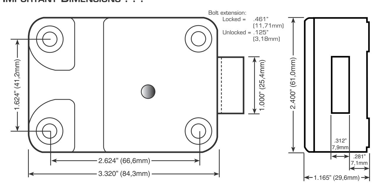
• A minimum distance of .150" (3,8 mm) is required between the end of the lock case containing the bolt and the safe's blocking bar or cam plate which is normally blocked by the extended lock bolt.

• Do not allow the safe's blocking bar or cam plate to depress the electronic lock's bolt farther than it retracts during normal motor operation. This can lead to inconsistent lock operation.

Sargent & Greenleaf, Inc.
One Security Drive, Nicholasville, Kentucky 40356 Phone (800) 826-7652 FAX (800) 634-4843
Sargent & Greenleaf S.A.
9, chemin du Croset, 1024 Ecublens, Switzerland Phone 41-21-691-9583 FAX 41-21-691-5349
INSTALLATION NOTES . . .
Sargent & Greenleaf strongly recommends the following procedures be performed only by an experienced locksmith or safe technician. It is likely that your safe incorporates relocking devices that are attached to the combination lock. Misalignment or detachment of these devices can result in a lockout—a condition where the safe cannot be opened without damage.
ADDITIONAL ITEMS YOU WILL NEED . . .
Most installations can be performed with a small phillips screwdriver, medium phillips screwdriver, small flat blade screwdriver, a drill motor, a #23 drill bit, and a 1 ⁄4" drill bit.
If the manufacturer of your safe has made external relock device attachments to the lock, it is likely that specialized tools and knowledge will be required.
INSTALLATION . . .
Step 1
Remove the existing lock (if present). The mounting plate should be smooth and flat, with 1 ⁄4 -20 mounting screw holes. The wire channel (spindle hole) must have a diameter of at least 3 ⁄8 inch. Use a reamer or round file to remove any sharp edges from the wire channel (spindle hole) that might damage the wire cable.
The 6150 can be mounted right-hand, lefthand, vertical-up, or vertical-down without any modifications or adjustments.
Step 2
Using a small phillips screwdriver, remove the single screw near the bottom of the keypad's front surface. You can then remove the mounting base and attach it to the front of the safe. Its mounting holes match those of dial rings used with mechanical combination locks.
You can use the old ring's mounting screws or the ones provided in the 6150 accessory package. Use two screws.
Use a file or reamer to remove any burrs or sharp edges around the safe's spindle hole. Then route the cable assembly from inside the safe through the spindle hole.
The connector requires a minimum spindle hole diameter of 3 ⁄8" (9,5 mm). Do not attempt to force the connector through a smaller opening.
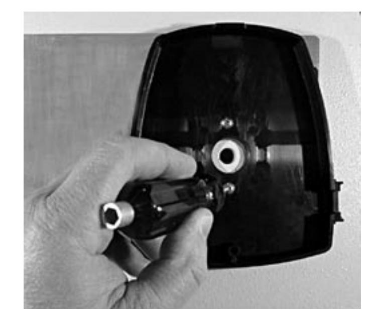
Step 4
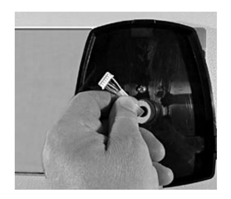
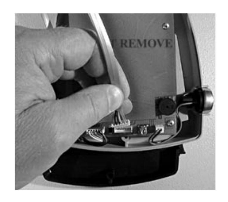
The connector is shaped so that it will fit into the keypad's circuit board receptacle only when aligned correctly. Insert the connector into its receptacle. If it does not slide easily into place, do not force it. This means you need to turn it 180 º before attempting to insert it again.
Step 5
Place the keypad cover over its mounting base. As you do this, pull all excess cable from the inside of the safe door.
Hook the tab at the top of the cover into the matching slot in the mounting base, then fix the cover to the base with the single attaching screw.
The cable coming from the lock body stays inside the safe and is not routed through the door's spindle hole, which already contains a cable. Route the e.c.u. cable in the channel cast into the underside of the lock case as you position the lock on the mounting surface. Make sure the cable is not pinched or crimped.
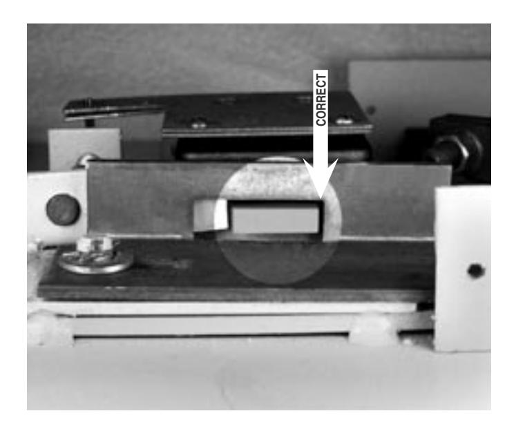
Use four 1 ⁄4 -20 (or metric M6) screws to securely attach the lock to the mounting plate. The lock uses a bolt-through cover that allows mounting with the cover in place. Removing the cover will void the product warranty. This photo shows a gap between the end of the lock body and the
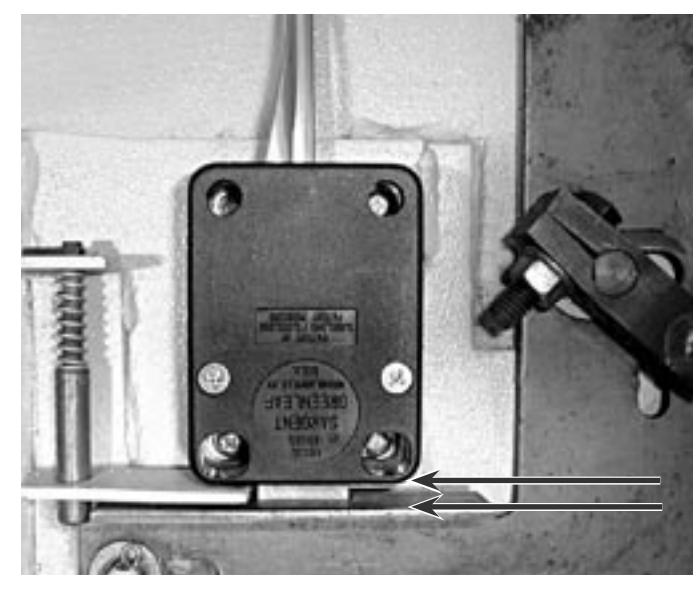
blocking bar of the safe's boltwork (see arrows). This gap should always be a minimum of .150" (3,8 mm).
Step 7
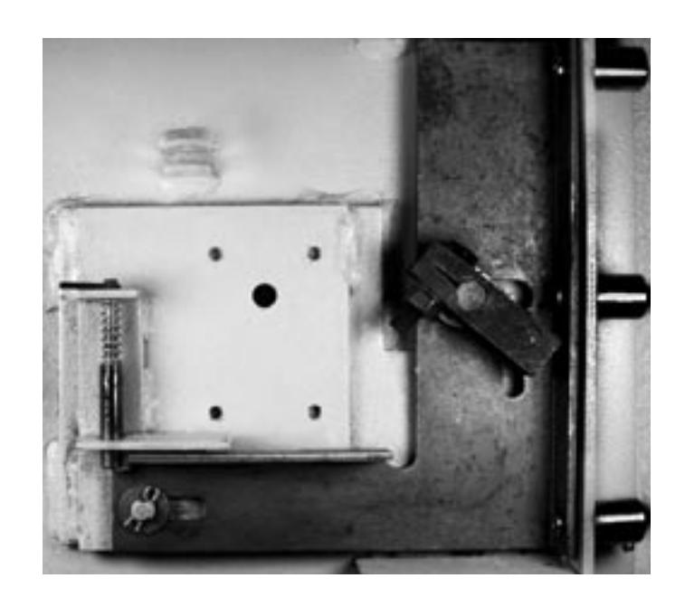
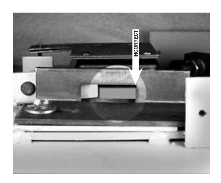
Make sure that the lock bolt does not bind against the safe's boltwork. 6150 locks are sensitive to bolt end and side pressure. The safe's blocking bar or cam must not depress the lock's bolt farther than it retracts under normal motor operation. Check to make sure this doesn't happen when the safe handle is moved to retract the door bolts (unlock the safe).
This photograph shows boltwork in the locked position which places pressure on the side of the lock bolt. This could prevent the lock from opening properly.
Step 8
The boltwork bind has been relieved by removing a small amount of material from the right side of the boltwork opening. When the safe's boltwork is fully thrown to the locked position, there is an air space on all sides of the electronic lock's bolt.
The electronic control unit (e.c.u.) should be mounted on the inside of the safe door if there is sufficient space (6" x 8" x 1.5" or 15,3 cm x 21 cm x 4 cm). Otherwise, it can be mounted on an inner safe wall. The e.c.u. should be mounted as close to the lock as possible to minimize cable length. If the e.c.u. is mounted inside the safe (rather than on the door), protect cables using flexible sleeving, and provide service loops across the door hinge area to avoid cable stress.
Use the holes in the e.c.u. baseplate to mark the four mounting screw holes. Use a #23 bit to drill the holes. Then attach the e.c.u. using four #8-32 thread-cutting screws provided.
Drill a maximum 1⁄4" hole through the back of the safe for power wires. Use a reamer or file to smooth rough edges. The hole cannot be in a location that allows direct viewing or manipulation of any lock parts.
Step 10
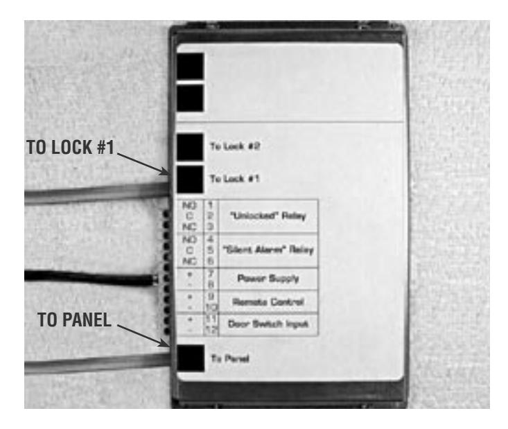
Connect the cable from the keypad to the e.c.u. jack marked "To Panel." Connect the cable from the lock to the e.c.u. jack marked "To Lock #1." If additional locks are used, they are connected to jacks marked "To Lock #2, #3, and #4." Other available features requiring e.c.u. connections are "Unlocked Relay," "Silent Alarm Relay," "Remote Control," and "Door Switch Input" (see contact electrical specifications on the following page).
Step 11
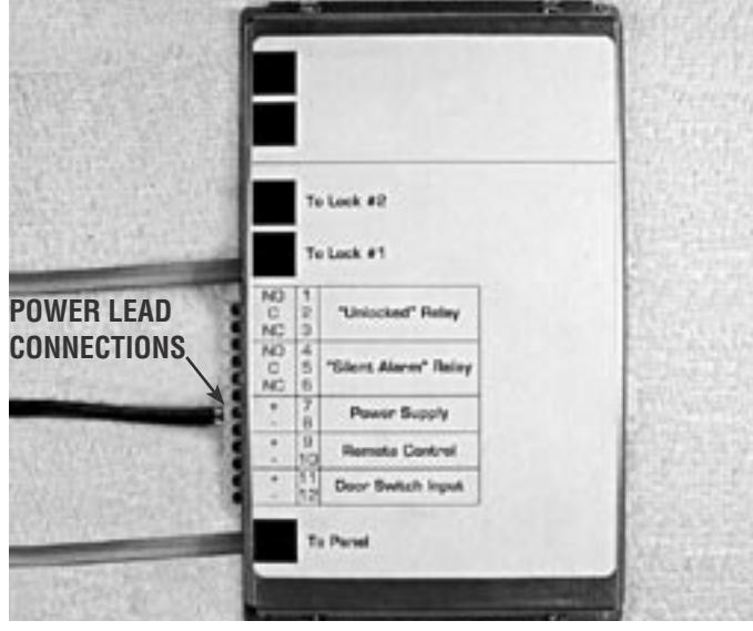
Run the power supply leads from the plugin transformer through the hole you drilled in the back of the safe to the e.c.u. Secure the wires using cable clamps provided. Attach the black wire with white marking on it to e.c.u. terminal #7 (positive). Attach the plain black wire to terminal #8 (negative).
Plug the 6150's power supply into a 120 volt AC, 60 Hertz power source.
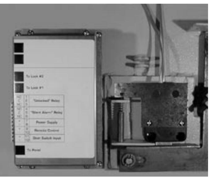
Note that this installation requires the attachment of a relock device plate to the back of the lock. It is mounted over the lock cover at the cover screw locations. This requires removal of the original cover screws so that longer #8-32 machine screws can be substituted. Make sure replacement screws engage at least four threads of the lock case, and that they hold the cover firmly against the lock case.
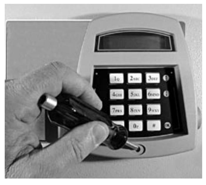
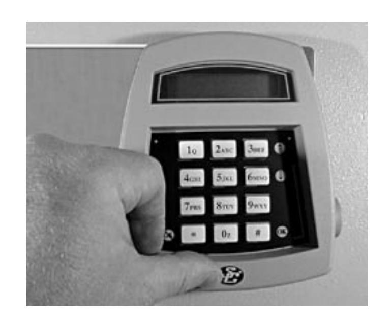
It is recommended that you check your lock's functions before installing the logo button that covers the keypad screw.
Remove the protective backing from the logo button, and press it into place in the recess provided over the keypad screw.
The installation is complete. Refer to your lock's operating instructions.
CHECK TO MAKE SURE YOUR LOCK OPENS AT LEAST THREE TIMES BEFORE CLOSING THE SAFE DOOR.
6150 Electrical Specifications . . .
Remote Control Input
9 to 15 volts DC @ less than 30 mA
Door Switch Input
SPST switch only (no voltage or current input)
Unlocked Relay Contacts
1 amp @ 24 volts DC
Silent Alarm Relay Contacts
1 amp @ 24 volts DC
AC Adapter
input 120 volts AC 60 Hz 65 mA output 9 volts DC 75 mA
IMPORTANT DIMENSIONS . . .