Sargent & Greenleaf Electronic Safe Lock Series S&G 6129 Installation
Open the original PDF document
View PDF6129 Motorized Electronic Combination Lock
Installation Instructions
This Sargent & Greenleaf 6100 series electronic lock combines ease of operation with security. Advanced electronic circuit design makes it easy to install, easy to open, and easy to change codes. Follow these instructions carefully to get the best possible performance from your lock.
MOUNTING CONSIDERATIONS
- Sargent & Greenleaf 6100 series Motorized Electronic Combination Locks have been designed to use the same mounting screw locations and occupy the same space as a standard S&G 6730 mechanical lock. The 6100 series uses stan-
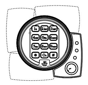
- The keypad diameter is 4 inches (101.6mm). This is slightly greater than the diameter of standard S&G dial rings for mechanical locks. The 61KP series keypad will cover any scratches or paint blemishes left by the old lock.
dard mounting dimensions to simplify retrofit in existing safes.
- Modifications to the lock are not recommended, and will void the manufacturer's warranty.
- The 6129 is designed to have boltwork blocking devices attached to the end of the lock bolt. It is designed to move a 2.25 lb. (10 newton) load. The maximum intermittent load must not exceed 5.5 lbs. (25 newtons).
- The direction of movement of the device attached to the end of the lock bolt must be in line with the direction of movement of the lock bolt. Any misalignment will adversely affect performance.
- The 6129 lock requires installation of a microswitch (not included), which activates extension of the lock bolt.
- You should install fresh alkaline batteries in the keypad and connect the lock wiring cable to check the functions of the lock prior to installation. Follow the procedures given in the Operating Instructions.
- The 6129 is normally installed with the keypad extension base to allow use of the lock's sophisticated security features. However, it can be installed without the keypad extension when these features are not required or will be utilized at a later date.
Sargent & Greenleaf, Inc.
One Security Drive, Nicholasville, Kentucky 40356 Phone (859) 885-9411 FAX (859) 887-2057
Sargent & Greenleaf S.A.
9, chemin du Croset, 1024 Ecublens, Switzerland Phone 41-21-691-9583 FAX 41-21-691-5349
INSTALLATION NOTES . . .
We strongly recommend the following procedures be performed only by an experienced locksmith or safe technician. Your safe may incorporate relocking devices that are attached to the combination lock. Misalignment or detachment of these devices can result in a lockout—a condition where the safe cannot be opened without damage.
ADDITIONAL ITEMS YOU WILL NEED . . .
The 6100 series requires two 9-volt alkaline batteries (not included). We recommend fresh Duracell® batteries. Do not use old or partially drained batteries in your lock.
Installation requirements vary greatly from one safe to the next. Some installations can be performed with nothing more that a medium phillips screwdriver. Others require specialized tools and a thorough understanding of how the safe's boltwork mechanism operates under different conditions.Have your lock professionally installed to avoid potential problems.
INSTALLATION . . .
Step 1
Remove the existing lock (if present). The mounting plate should be smooth and flat, with 1 ⁄4 -20 (M6) mounting screw holes. The wire channel (spindle hole) must have a diameter of at least 5 ⁄16 inch (8 mm).
6100 series locks are designed to be mounted right-hand, left-hand, vertical-up, or vertical-down without any modifications or adjustments.
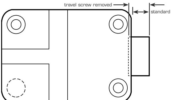
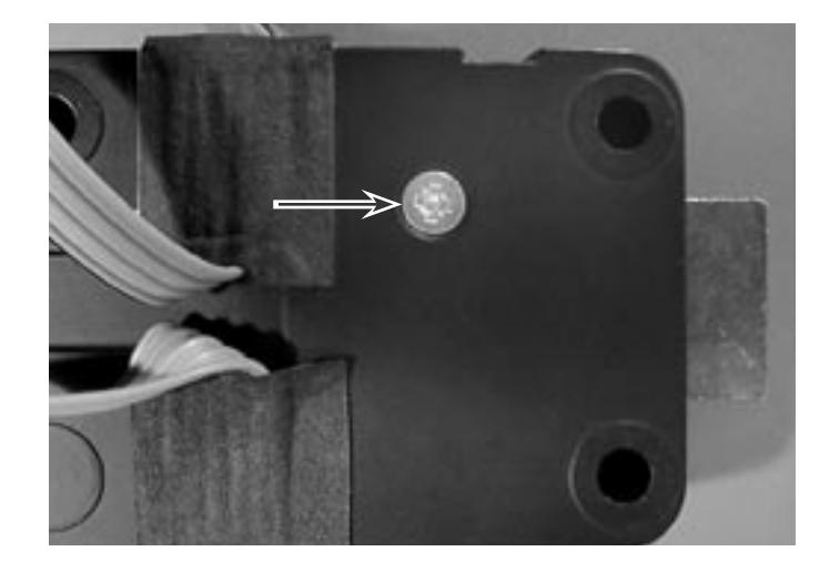
Step 2
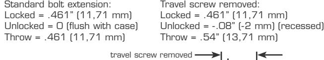
Determine the bolt throw required for this application. If it's more than .46" (11,7 mm), remove the bolt travel adjustment screw and add the enclosed .075" (2 mm) thick spacer when attaching the safe's boltwork to the lock bolt.
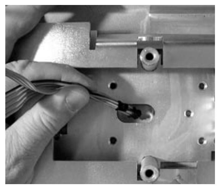
Use a reamer or round file to remove any sharp edges from the wire channel (spindle hole) that might damage the cable.
Run the two connectors and their cables through the wire channel. Gently pull the connectors and all excess cable to the outside of the safe. Make sure the cable is not crimped or stressed at any point. It is very important to avoid crimps between the lock body and mounting plate.
Step 4
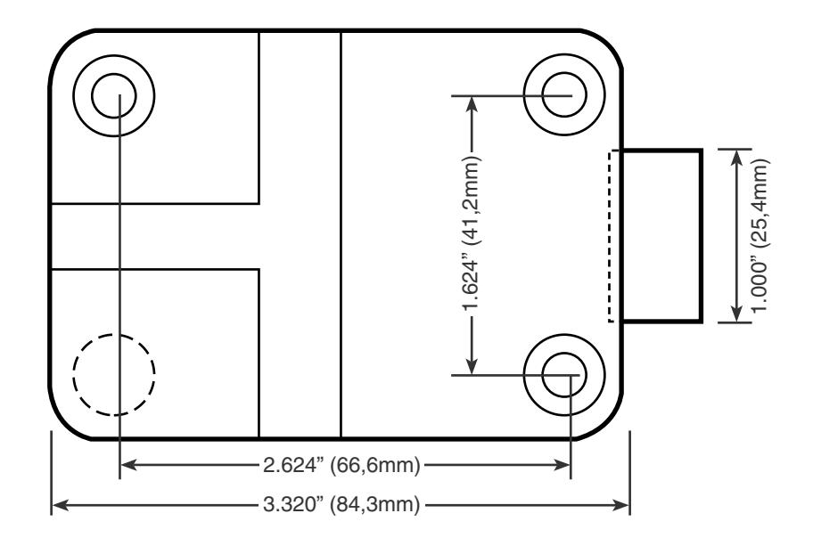
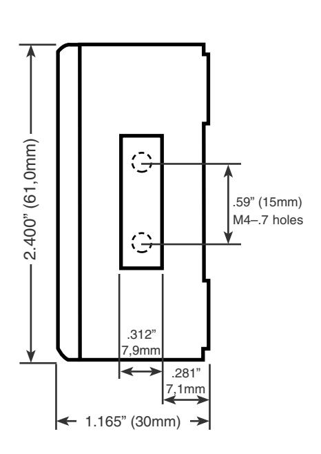
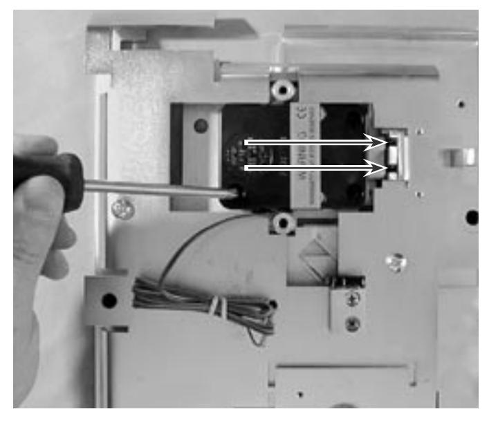
In this particular installation, it is best to thread the two boltwork attaching screws into the end of the lock bolt before fixing the lock to the safe's mounting plate. Two M4–.7 holes on a 15mm center are provided in the end of the lock bolt for making boltwork attachments.
Boltwork attaching screws are not provided with the lock because of the great number of possible sizes required.
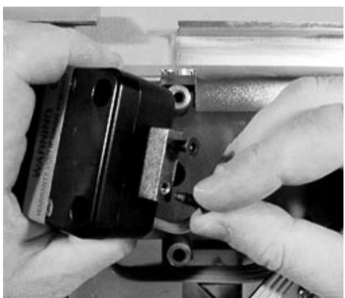
Step 5
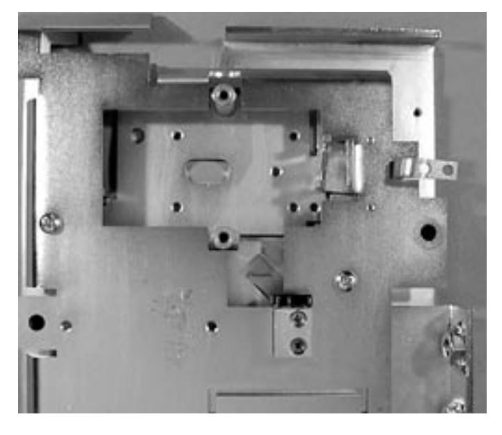
In our example installation, the lock is now placed on the mounting plate, with great care exercised to be sure all excess cable is pulled to the front of the safe door. The partially installed bolt screws slide into slots in the door's boltwork mechanism (arrows identify bolt screw locations).
The lock body is then attached firmly to the mounting plate, using three 1 ⁄4 -20 (M6) mounting screws (provided).The lock incorporates a bolt-through cover that allows mounting with the cover in place. Removing the cover voids the product warranty.
Note for safes with relock devices: Some installations require attachment of the safe manufacturer's relock device plate to the lock using the cover screws. If this is the case, be sure the thickness of the relock device plate(s) is not great enough to prevent the screws from engaging the lock case by at least four threads. If necessary, use longer 8-32 (M4) machine screws to ensure proper fit.
Two wire leads from the lock are for connection to a normally open (NO) boltwork microswitch (not provided). Make sure the switch is adjusted so that it closes only when there is a minimum .040" (1 mm) clearance for the lock bolt to fully extend.
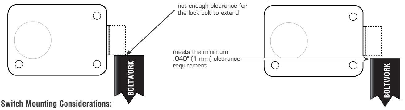
Location—Whenever possible, position the boltwork switch to sense the location of the cam plate or blocking bar that interacts directly with the lock bolt
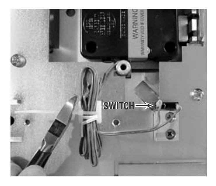
Switch Overtravel—Ensure the switch is mounted in the boltwork so that the switch manufacturer's overtravel limits are not exceeded. Special care must be taken to ensure the boltwork travel does not use the switch as a stop.
SWITCH SPECIFICATIONS:
minimum voltage rating: 30 VDC
minimum current rating: 50 milliamperes
electrical contact material: silver switch operation: snap acting contacts
contact configuration: lock bolt extends on contact closure switch actuator: recommend lever or roller actuator, depending on
boltwork design
switch operating life: minimum of 50,000 cycles
switch connectors: recommend .110" (2,8 mm) X .020" (0,5 mm)
quick connect tabs
Step 7
Use wire ties as necessary to route the switch wire away from moving boltwork components, and make sure the switch does not close the 6125 circuit until the boltwork is fully extended.
Step 8
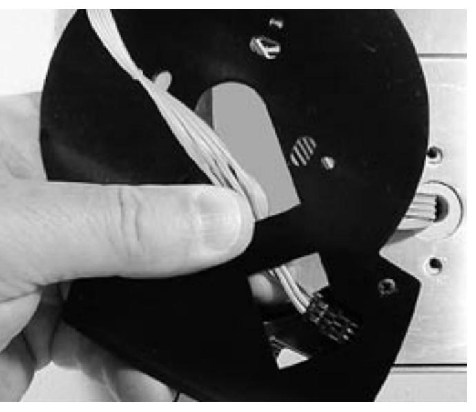
The lock's two cables use distincly different connectors. Upon inspection, you will easily be able to determine which one plugs into the keypad and which one plugs into the keypad extension.
Run the appropriate connector and wire cable through the center hole of the keypad extension, and route it as shown. Plug the connectory into its receptacle in the extension. Before placing the extension against the safe door, be sure to pull all excess cable through to the front of the extension.
Place the keypad base over the extension, and pull both cables through the base's center opening.
The extension can be positioned in any of four possible orientations (see below) to prevent interference with the safe handle or other door hardware. Use the two 8-32 (or M4 screws provided to attach the keypad base (and the extension underneath it) to the front of the safe.
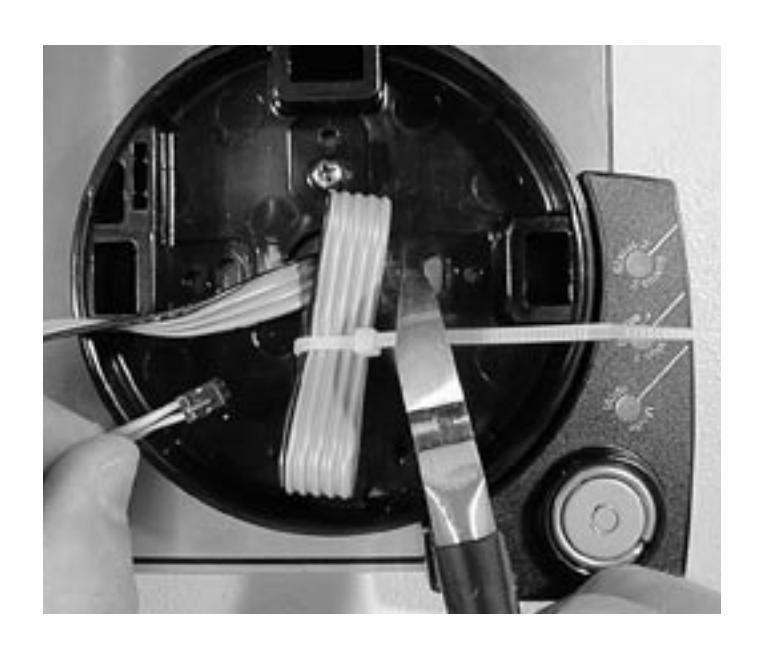
Excess extension cable should be neatly folded and secured with a wire tie.
Step 10
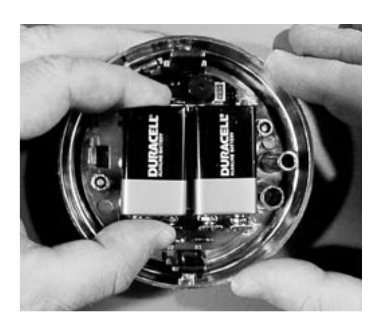
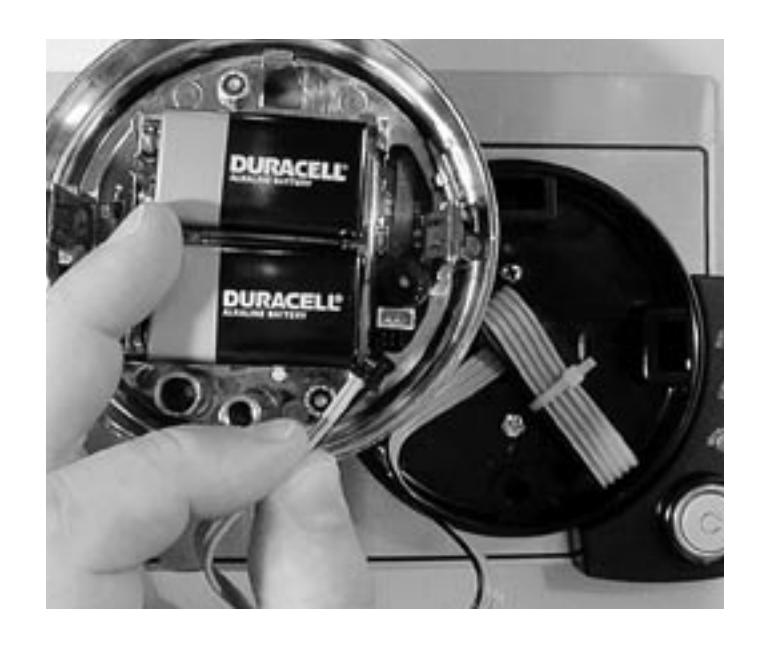
Install a new 9-volt alkaline battery in each of the keypad's battery holders (Duracell® is recommended). Support the top of each holder as the battery is inserted. This will prevent bending or braking the holder.
Step 11
The keypad cable connector is shaped so that it will fit into the circuit board receptacle only when aligned correctly. Insert the connector into its receptacle in the keypad housing. If it does not slide easily into place, do not force it. This means you need to turn it 1800 before attempting to insert it again.
When the lock cable connector is plugged into the keypad, the keypad will not work (no sound or LED flash when keys are pressed) until the keypad is installed into the base following steps 12 and 13.
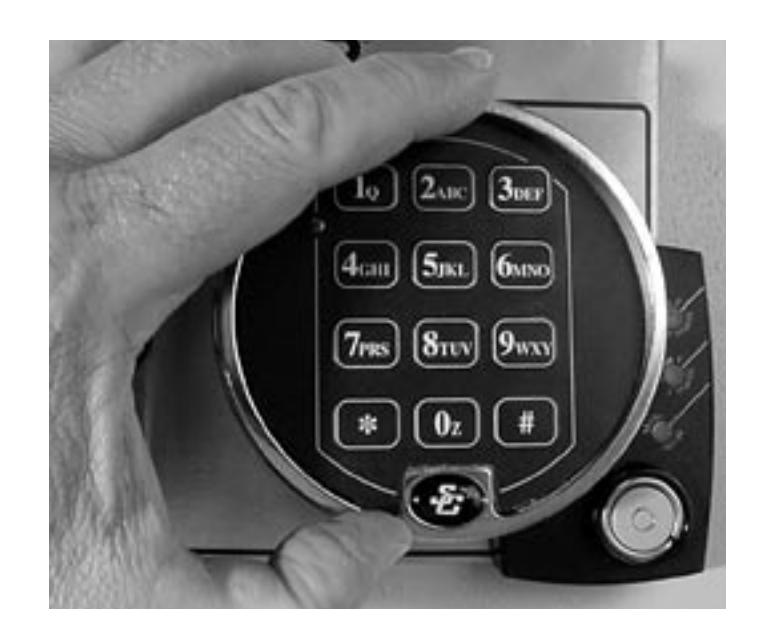
Place the keypad over the base. Make sure the wire cables are still clear of the two spring clips, then push the keypad firmly onto the base. It should snap into place.
Note: To remove the keypad, pull the bottom (area nearest the S&G logo) away from the mounting base first.
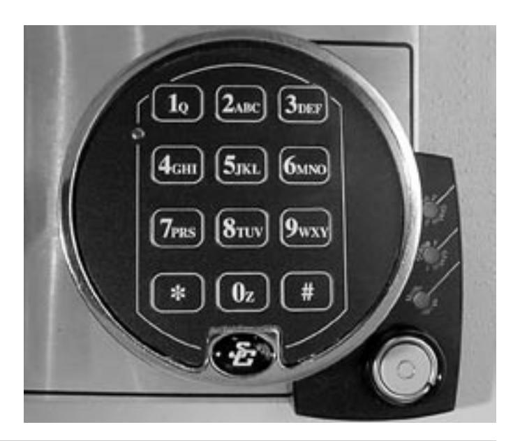
Step 13
The installation is complete. Refer to your lock's Operating Instructions for opening, code changing, time delay, and battery changing instructions. You will need to reset the tamper indication before the lock will operate. See the Operating Instructions for the required procedure.
MAKE SURE YOUR LOCK IS FULLY OPERA-TIONAL BEFORE CLOSING THE SAFE DOOR FOR THE FIRST TIME.
IMPORTANT DIMENSIONS . . .