Sargent-Greenleaf-Electronic-Safe-Lock-Series-Biometric-KP-Installation
Open the original PDF document
View PDFInstallation Instructions
Biometric Keypad

Mounting Considerations
- Always refer to the installation and operating instructions for the lock and keypad before attempting installation of any of the components. This will give you an overall understanding of how the components relate to each other and connect to each other.
- Modifications to the Biometric Keypad are not recommended, and will void the manufacturer's warranty.
- The area where the Biometric Keypad is to be mounted should be flat and free of any surface irregularities. Tightening it down on an uneven surface could cause damage to the unit.
- Route all cables in a manner that leaves them free of sharp bends or kinks. Avoid crushing the cables under components as they are fastened to the safe.

• Install the lock first. Refer to the mounting instructions that came with the lock for this operation.
Sargent & Greenleaf, Inc.
A Wholly Owned Subsidiary of Stanley Security Solutions, Inc. PO Box 930, Nicholasville, Kentucky 40356 USA Phone (859) 885-9411 Phone (800) 826-7652 FAX (859) 887-2057 FAX (800) 634-4843
Sargent & Greenleaf S.A.
9, chemin du Croset 1024 Ecublens, Switzerland Phone +41-21 694 34 00 FAX +41-21 694 34 09
Installation Notes
Although S&G electronic safe lock components are quite easy to install, we recommend the following procedures be performed only by a knowledgeable locksmith or safe technician. He or she is experienced in recognizing and correcting unsuitable mounting conditions which could adversely affect the operation of your locking system.
Additional Items You Will Need
If fresh 9-volt alkaline batteries are not included, you will need to supply two. We strongly recommend Duracell® brand alkaline batteries. Your locking system will give optimum performance with this battery. Do not use an old or partially drained battery in your lock, and do not use anything other than an alkaline battery.
Most installations can be performed with nothing more than a medium phillips screwdriver. In some installations, however, the safe design will dictate the use of specialized tools. This is yet another reason to have your installation performed by an experienced safe technician or qualified locksmith.
Installation
Step 1
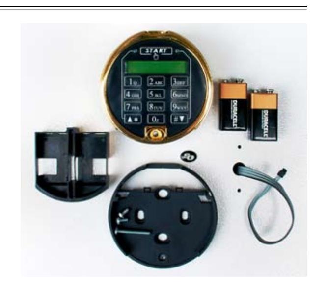
Shown here are the components of your Biometric Keypad. If batteries are not included with your keypad, you will need to obtain two, fresh, Duracell® 9-volt alkaline batteries. The lock and keypad will work with any brand of alkaline batteries, but our laboratory tests show that these components work best with Duracells.
Following the instructions packaged with the lock, mount the lock body to the inside of the door. The cable coming from the lock should be routed through the door's spindle hole as shown.
Step 2
The underside of the keypad base has raised areas at the mounting screw locations. The rest of the base is recessed, allowing lots of space in which to route the lock cable. When you turn the base over to fasten it to the front of the safe, make sure the cable will not be pinched between a raised surface and the safe door. Pinching the cable this way can lead to lock failure, either immediately or after it has been in service for some time.
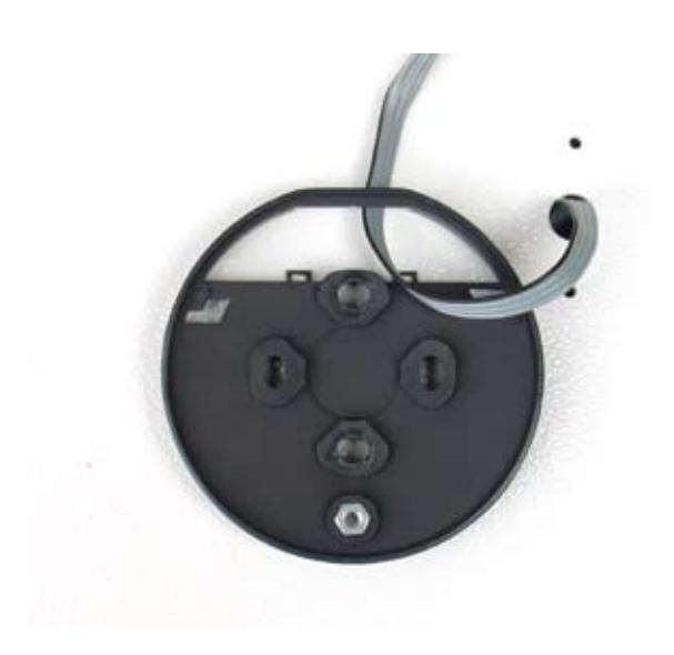
Note where the cable has been placed through the large opening at the top of the base. Fasten the base to the front of the safe, using the machine screws provided. The silver colored screws are 8-32, and the bronze colored screws are M6. Use whichever set is appropriate for the holes provided in the safe door. Discard the remaining set.
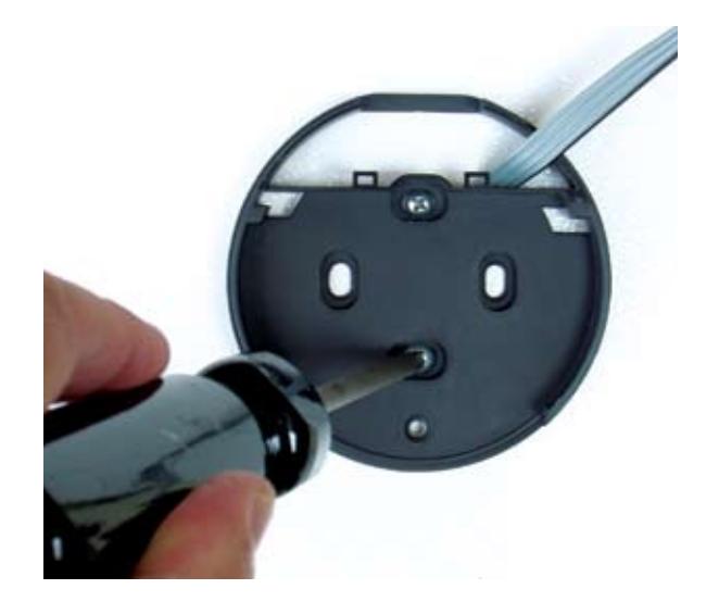
The recommended tightening torque for the base mounting screws is from 4 to 12 inch-pounds (45.2 to 135.6 newton-centimeters) . The placement of the base's mounting screw holes is the same as for other S&G keypads and dial rings.
Do not use liquid thread sealers, as they may react with the base material, causing it to warp or crack.
Step 4
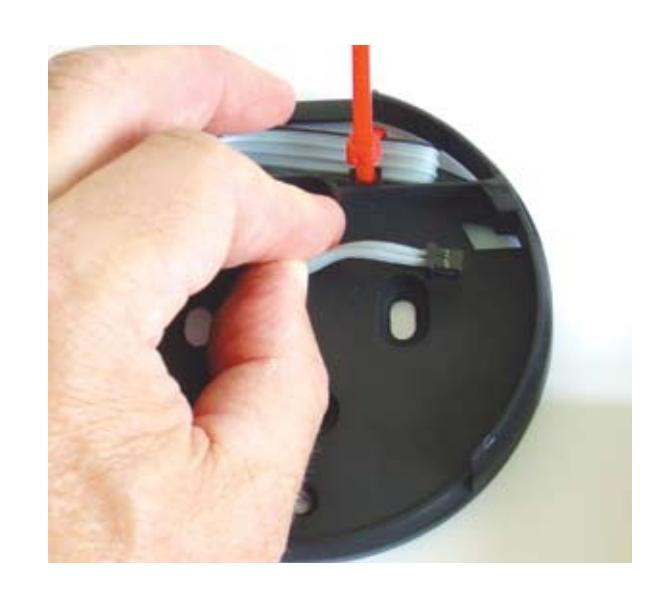
If there is excess lock cable, it can be carefully folded and secured with a wire tie (not included). Two slots have been provided at the bottom of the cable opening to secure ties. It is not necessary to tie the cable in place, as long as it is neatly folded in the cable opening area before the keypad is attached to the base.
Step 5
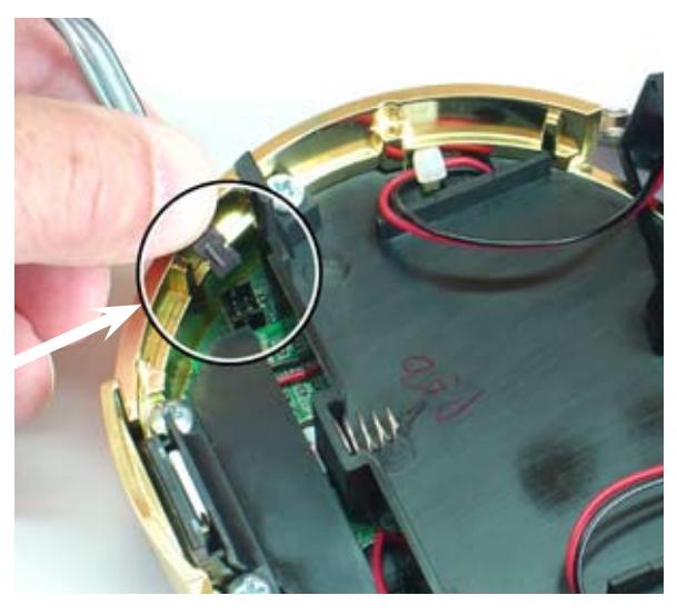
The cable connector and circuit board receptacle are configured so the connector can only be inserted when oriented correctly. Close inspection will reveal raised ridges on the connector and corresponding slots in the receptacle. These features must be aligned before the connector is inserted. Proper insertion of the cable is shown here.
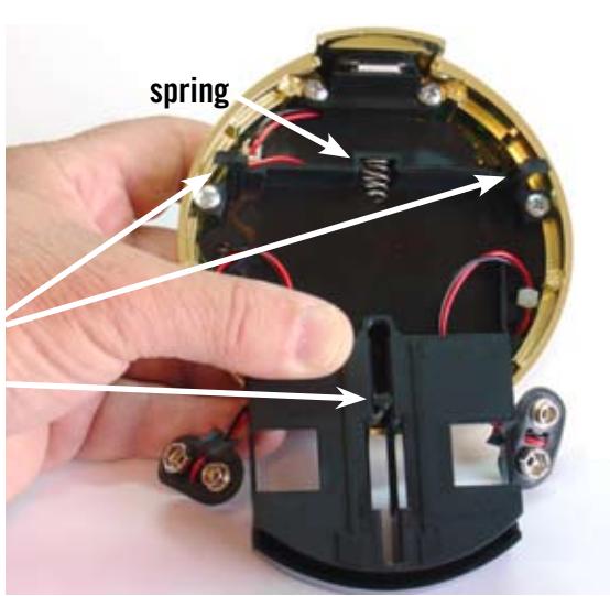
Place the battery compartment in the underside of the keypad. Note that the guide post is in the slot which is centered in the compartment. Each battery cable is routed through the top of the compartment—one on the left and one on the right. Make sure the battery wires do not get bound around the keypad's mounting feet or in the spring.
guide post mounting foot
Step 7
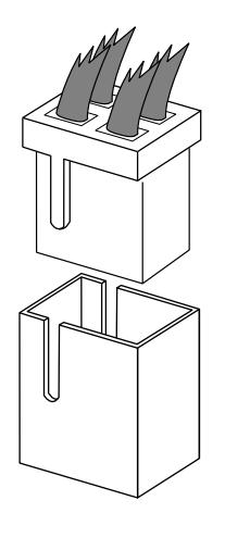
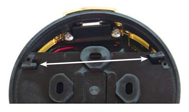
Holding the battery compartment in place, turn the keypad over and place it on the base. You may find it easiest to place the keypad so that it is about 8 to 10 degrees clockwise (or right) of being aligned with the base, pressing downward slightly, then rotating the base counterclockwise to align it exactly with the base.
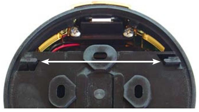
These photos show the bottom side of the keypad base. Obviously, you can't see this when the base is installed on the safe, but this view illustrates the engagement of the keypad feet in the openings provided in the base. The top photo shows the position of the two feet when the keypad is first placed on the base. The bottom photo shows the position of the feet after the keypad is rotated counterclockwise. Now the feet are locked into the base openings.
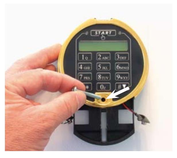
Once the keypad is in place, fasten it with one of the long machine screws provided. One is a standard phillips head. The other is a oneway design, making it difficult to remove. Use this screw only if your security needs require the keypad to be difficult to remove from its base, once installed.
The recommended tightening torque of the long screw is 4 to 6 inchpounds (45.2 to 67.8 newton-centimeters).

Step 9
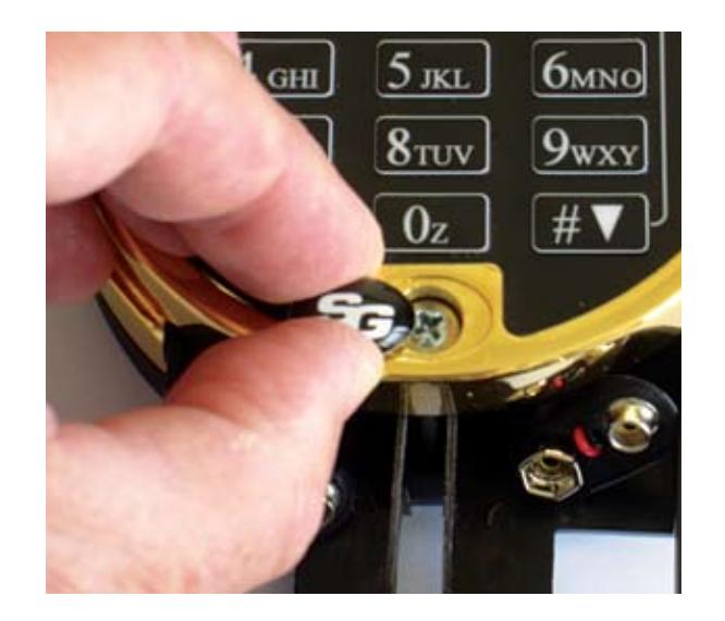
Peel the protective backing from the underside of the included S&G logo button. Place it in the recess provided for the keypad attaching screw, and press it into place.
Step 10
Connect a battery to each of the snap-on connectors. Note that the connector is oriented so that the part of the snap-on cap where the wires come out (white arrow) is closest to you.
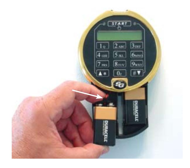
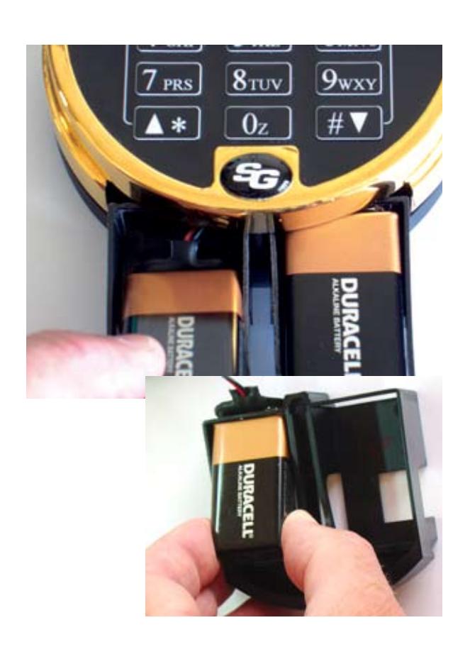
Place each battery into its section of the compartment as shown. Be careful to avoid scraping or binding the battery wires.
The smaller photo shows proper positioning of the battery cable clip under the cross bar of the battery drawer. The drawer will slide into the keypad much easier if you position the battery cable clip as shown. For clarity, the photo shows the drawer removed from the keypad. However, it is not removable once the keypad is installed on its base.
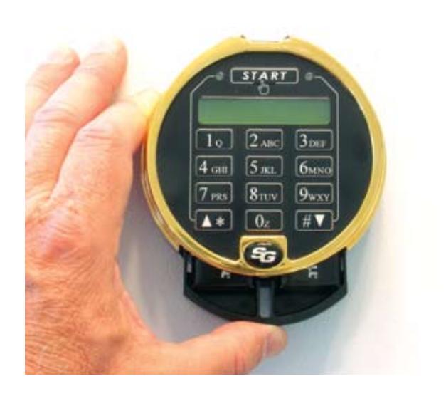
Step 12
Once the batteries are in place, push the battery compartment up into the keypad. It should snap into place when fully inserted.
You are now ready to proceed to the Biometric Keypad setup and operating instructions.

Sargent & Greenleaf, Inc.
FAX (800) 634-4843
A Wholly Owned Subsidiary of Stanley Security Solutions, Inc. PO Box 930, Nicholasville, Kentucky 40356 USA Phone (859) 885-9411 Phone (800) 826-7652 FAX (859) 887-2057
Sargent & Greenleaf S.A.
9, chemin du Croset 1024 Ecublens, Switzerland Phone +41-21 694 34 00 FAX +41-21 694 34 09