Sargent & Greenleaf Electronic Safe Lock Electromechanical Government Security Lock SG2740A Operating
Open the original PDF document
View PDFOperating Instructions
S&G© Model 2740 Electromechanical Safe Lock
The S&G© 2740 Model Electromechanical Safe Lock combines the familiar operation of a mechanical lock with the advanced security features of a sophisticated electronic device. Be sure to follow these instructions carefully to get the best possible service from your lock.
Introduction
- The S&G© Model 2740 Electromechanical Safe Lock is shipped from the factory in single user mode with a factory shipping combination of 50-25-50 . This combination is used to open the lock and change the combination(s). It is also used in conjunction with the setup module to access the lock for calibration, setup, and maintenance. You should set the lock to your own, unique combination(s) before storing anything of value in the safe or cabinet.
- All setup, maintenance, and troubleshooting operations must be performed with the safe or container OPEN . Never close the container with either a change key or the setup module attached . At the conclusion of a combination change or service operation the lock should be checked to make sure it operates at least three times consecutively on the intended combination before closing the safe or container. The setup module must be disconnected to test the lock.
- The lock will sometimes emit a beep or series of beeps to communicate its state. A table of the eleven possible beep patterns is included in this document (page 12).
- All combinations must contain three numbers, ranging anywhere from 0 to 99. Unlike mechanical locks, the 2740 has no forbidden zone, and it does not have a restriction on how close adjacent numbers of the combination may be to one another.
- If you stop dialing for more than ten seconds, the lock will reset, forcing you to begin the combination entry sequence all over again.
- If ten incorrect combinations are entered in a row, the S&G© Model 2740 Electromechanical Safe Lock will shut down for a period of ten minutes. Entering a correct combination resets the wrong combination counter. It doesn't make any difference how much time intervenes between consecutive wrong combination entries. There is no alternative to waiting for the penalty time to expire.
- The S&G© Model 2740 Electromechanical Safe Lock is powered by a main battery (CR123A lithium camera-type), and also uses a long-life backup battery (CR2450 coin cell). Both batteries must be changed at the same time by an S&G Certified Technician.
- The 2740 will switch to the backup battery and latch OPEN if the ten-beep low battery signal is repeatedly ignored. Opening with the backup battery may take as long as five seconds after the combination is entered. If you find that your lock will not lock, the batteries will have to be replaced, and it will need to be reset by an S&G 2740 Certified Technician using a setup module.
- The lock's combination can be changed by use of the setup module or a separate change key. Only an S&G 2740 Certified Technician should use the setup module. The change key can be used by a safe custodian or security officer following the appropriate instructions included in this document.
- Lock bodies and covers are matched components. Do not replace a lock cover with the cover from another lock. At best, this will produce erratic lock operation.

Sargent & Greenleaf, Inc. A Wholly Owned Subsidiary of Stanley Security Solutions, Inc. PO Box 930
Nicholasville, KY 40340-0930
Phone: (800)-826-7652 Fax: (800)-634-4843 Phone: (859)-885-9411 Fax: (859)-887-2057
Sargent & Greenleaf S.A. 9, chemin du Croset 1024 Ecublens, Switzerland Phone: +41-21 694 34 00 Fax: +41-21 694 34 09
Table of Contents
| Operating the 2740 | |
|---|---|
| Introduction to the 2740 | front page |
| Dialing Procedures | |
| Opening the Lock in Single User Mode | page 3 |
| Opening the Lock in Dual User Mode | page 3 |
| Combination Changing | |
| Change Key | page 4 |
| Combination Changing Notes | page 4 |
| Changing the Combination with the Change Key | page 4 |
| The Setup Module | |
| Introduction to the Setup Module | page 5 |
| Setup Module Functions | page 5 |
| Battery Condition | page 5 |
| Combination Change | page 5 |
| Single User Mode | page 5 |
| Dual User Mode | page 5 |
| Unknown Combination | page 5 |
| Latch Open | page 5 |
| Calibrate | page 5 |
| Setup Module Operation | |
| Setup Module Connection | page 6 |
| Battery Condition Function | page 7 |
| Combination Change Function | page 7 |
| Single User Mode Function | page 8 |
| Dual User Mode Function | page 9 |
| Unknown Combination Function | page 10 |
| Latch Open Function | page 11 |
| Calibration Function | page 11 |
| Beep Patterns and What They Mean | page 12 |
| Battery Changing Instructions | |
| Low Battery Condition | page 13 |
| Battery Replacement Procedure | pages 13 & 1 |
| Warranty Statement | page 14 |
Operating Instructions
S&G© Model 2740 Electromechanical Safe Lock
☞ Important Dialing Notes
Whenever you are dialing to a combination number, it is important to avoid "overshooting" the number, then backing up to it. If you overshoot the number, you can continue rotating the dial in the same direction for an extra turn (or two, or three...etc.), then stop precisely on the desired number. For the sake of clarity, these instructions indicate a specific number of dial turns for entry of each number of a combination. However, unlike a mechanical lock, the dial can be rotated more than the minimum number of rotations for entry of any combination number.
The 2740 is locked by turing the dial left (counterclockwise) at least ½ revolution (at least 50 numbers).
To Open the Lock in Single User Mode
Single user mode simply means that one combination opens the lock. The opening index is the mark at the top of the dial ring at the 12 o'clock position. Follow this procedure:
- 1. Turn the dial left (counterclockwise) at least four complete revolutions, then stop precisely on the first number of the combination.
- 2. Turn the dial right (clockwise), stopping the third time the second combination number comes to the opening index.
- 3. Turn the dial left, stopping the second time the third combination number comes to the opening index.
- 4. Turn the dial right. If you have entered your combination correctly, the dial will come to a positive stop before you have turned more than 1 ½ revolutions.
If the lock emits 10 beeps upon opening, both lock batteries must be changed. The 10-beep low battery signal will repeat every twenty seconds for one minute after the lock is opened.
To Open the Lock in Dual User Mode
Dual user mode simply means that two different combinations are needed to open the lock. Typically, each combination is held by a different person for security reasons. Either combination can be entered first. The person who enters his or her combination last must complete the combination entry within two minutes of the first combination entry.
The opening index is the mark at the top of the dial ring at the 12 o'clock position. Follow this procedure:
- 1. Turn the dial left (counterclockwise) at least four complete revolutions, then stop precisely on the first number of the 1st combination.
- 2. Turn the dial right (clockwise), stopping the third time the second number of the 1st combination comes to the opening index.
- 3. Turn the dial left, stopping the second time the third number of the 1st combination comes to the opening index. Turn the dial right about ten numbers. The lock will emit four quick beeps.
- 4. Turn the dial left (counterclockwise), stopping the fourth time the first number of the 2nd combination comes to the opening index.
- 5. Turn the dial right (clockwise), stopping the third time the second number of the 2nd combination comes to the opening index.
- 6. Turn the dial left, stopping the second time the third number of the 2nd combination comes to the opening index.
- 7. Turn the dial right. If the two combinations have been entered correctly, the dial will come to a positive stop before you have turned more than 1 ½ revolutions.
Note: If either of the two combinations have not been dialed correctly, the lock will emit a brap (one long beep). Follow steps 1-7 again, making sure the correct combinations are dialed precisely to the opening index.
If the lock emits 10 beeps upon opening, both lock batteries need to be changed. The 10-beep low battery signal will repeat every twenty seconds for one minute after the lock is dialed open.
Combination Changing Instructions
S&G© Model 2740 Electromechanical Safe Lock
The Change Key
Combination Changing Notes
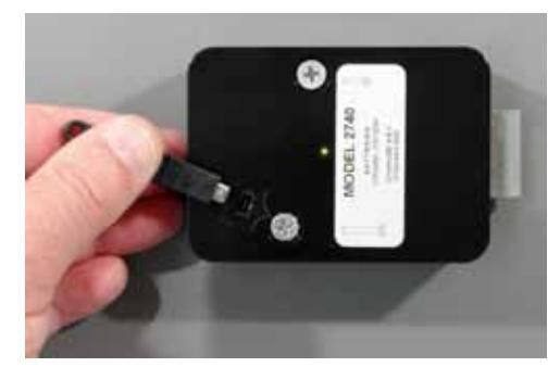
- 1. The change key only plugs into the lock cover one way. When the orientation is correct, the arrow in the connector will align with the arrow molded into the lock case.
- 2. In between programming steps, the lock will emit a series of quick beeps as the dial is turned clockwise. If the user continues to turn the dial too far clockwise after the beeps are emitted, the lock will interpret it as the next combination being entered incorrectly and it will emit a brap (one long beep). For example, during a combination change, after the old combination is entered, three quick beeps are emitted as the dial is turned clockwise. If the user continues to turn in the clockwise direction, the lock will think the new combination is being entered incorrectly. Therefore, you should stop turning clockwise immediately when the three quick beeps are heard.
- 3. If you begin a combination change and then decide not to proceed with it, you can simply wait two minutes for the change function to time out. At the end of the two minutes, a long tone will sound.
Changing the Combination with the Change Key
This procedure is used for locks in single user mode or dual user mode. The only difference is that each user of a dual user lock must change his or her own code independently.
The lock gives you two minutes to enter each combination (two minutes to enter the old combination, two minutes to enter the new combination for the first time, two minutes to enter the new combination for the second time). If you take longer, the lock will reset, and you will have to start again at the first step. Also, if you stop dialing a combination for more than ten seconds, the lock will reset, and you will have to start again at the first step.
The changing procedure is as follows:
1. Open the lock using the existing combination(s).
- 2. With the safe or container open, extend the lock bolt to the locked position.
- 3. Insert the change key into the receptacle in the lock cover.
The lock will emit one quick beep when you begin to enter your old combination as follows.
- 4. Turn the dial left at least four complete revolutions, then stop precisely on the first number of the old combination.
- 5. Turn the dial right (clockwise), stopping the third time the second old combination number comes to the opening index.
- 6. Turn the dial left, stopping the second time the third old combination number comes to the opening index. Then turn the dial right until you hear three quick beeps from the lock.
- 7. Turn the dial left (counterclockwise), stopping the fourth time the first number of the new combination comes to the opening index.
- 8. Turn the dial right (clockwise), stopping the third time the second new combination number comes to the opening index.
- 9. Turn the dial left, stopping the second time the third new combination number comes to the opening index. Then turn the dial right until you hear three quick beeps from the lock.
The new combination is entered again for verification.
- 10. Turn the dial left (counterclockwise), stopping the fourth time the first number of the new combination comes to the opening index.
- 11. Turn the dial right (clockwise), stopping the third time the second new combination number comes to the opening index.
- 12. Turn the dial left, stopping the second time the third new combination number comes to the opening index. Then turn the dial right, listening for five quick beeps to indicate a successful combination change. Continue turning the dial right to retract the lock bolt.
Do not close the safe door or container drawer until you have checked the new combination for proper operation at least three times with the door or drawer OPEN.
If you accidentally close the door with the change key in the lock, you can open it by going through the entire combination change procedure, beginning with step 4.
S&G© Model 2740 Electromechanical Safe Lock
The Setup Module
The Module is NOT for Everyone
The setup module is used to calibrate, program, and troubleshoot the 2740. In the hands of an S&G 2740 Authorized Technician it's a powerful and useful tool. Only an S&G 2740 Authorized Technician should connect a setup module to your lock.
Module Notes
If the 9V battery in the setup module is low, the red LED will emit a quick flash repetitively.
Do not keep the setup module plugged into the lock when not in use, as this will drain the 9V battery relatively quickly. It is recommended that the battery be removed from the setup module if the module is not being used.
A setup module with a yellow front is not capable of performing advanced maintenance functions.

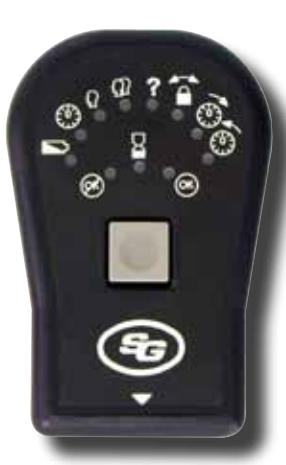
The gateway to the Model 2740's features is the setup module. It's powered by one internal 9-volt battery that also acts as the power source for the lock whenever the module is connected to the lock. The module has a single momentary contact button in the center, and several LEDs. The three LEDs located directly above the button are red, yellow, and green. When the red LED ( ) is the only one lit, it indicates that the module cannot do what you've asked it to do. It's an error signal. The yellow LED ( ) indicates that an operation is in process. The green LED ( ) lights to indicate that your operation has been successfully completed. These three "traffic signal" LEDs show you how your operations are progressing.
The top, semicircular row of LEDs are used to select and initiate lock functions. Following is a brief explanation of each function.

Battery Condition — The LEDs across the top of the setup module light up from left to right to indicate the condition of the main battery. The more LEDs that light up, the more energy left in the battery. It's a good idea to check battery condition each time the setup module is connected to the lock.

Combination Change*— This function is selected when you want to change the combination(s) used to open the lock.

Single User Mode — This option is selected when you want the lock to operate on one combination.

Dual User Mode — This option is selected when you want the lock to open only when two different combinations are entered within two minutes of each other.

Unknown Combination*— If the lock's combination is lost, the 2740 can be recovered and set to a new code. It requires temporary removal of the lock cover to view a unique serial number that is used in the recovery procedure.

Latch Open*— When the main battery is getting weak, the lock will alert the user via a series of beeps periodically whenever the lock is open. If these are ignored for about 100 openings, the lock will switch to the backup battery and latch open. The safe or container cannot be secured until the latch open condition is released and the batteries are replaced.
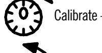
Calibrate — For proper operation, the dial must be synchronized precisely with the lock. The calibration function does this by having you set the dial right precisely to zero and set the dial left precisely to zero. Both the right and left calibrations must be completed to synchronize the dial with the lock.
* This function is not available on a setup module with a yellow front.
S&G© Model 2740 Electromechanical Safe Lock
Setup module Operation
You advance through the various setup module functions and select functions to perform by pressing the single module button. The current function is identified by the blinking of the LED next to an icon. To advance to the next function, quickly press the setup module's button. To select a function to perform, quickly press the button until the appropriate icon LED starts blinking, then press and hold the button for about one second. Remember that a quick press advances to the next function, and a long press (about a second) selects the function that is currently blinking. A button press either advances to the next function or selects a function depending on how long the button is pressed.
The setup module incorporates a magnetic back, allowing you to easily attach it to a safe door or container drawer while you working with it.
Setup Module Connection
The setup module is connected by using the existing combination(s) to open the lock.
- 1. Open the safe door or container drawer.
- 2. With the door or drawer OPEN, extend the lock bolt.
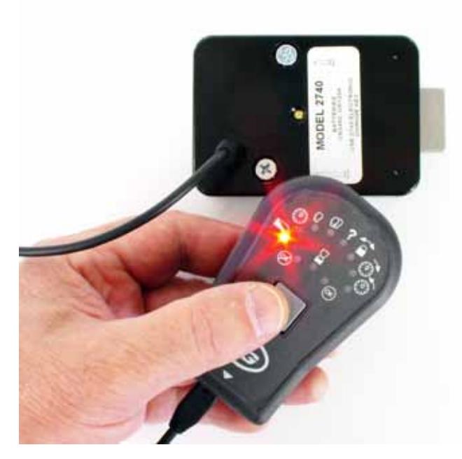
- 3. Plug the setup module cable's connector into the lock's change key receptacle, and press the module button briefly. The yellow LED will light momentarily, then the green LED will come on for two seconds. Following this, the battery condition LED will blink, which is the module's way of asking for further instructions. If you press the button for a second (long press), the module will display the battery condition. If you press the button quickly, the module will advance to the next function (which is combination change ).
Note: If the safe door or container drawer is closed and locked while the setup module is connected to the lock, simply refrain from touching the dial for at least two minutes. This allows the lock to reset, which will be confirmed by a single long beep. Then dial the existing lock combination as you normally would to open the container. The lock will open, even though the setup module is connected.
S&G© Model 2740 Electromechanical Safe Lock
Battery Condition Function

This function is activated by pressing the setup module button for one second when the LED next to the battery condition icon is blinking. Some or all of the other LEDs at the top of the module will light to indicate lock's main battery condition. The more LEDs that light, the stronger the battery. If no more than four LEDs light, you should change both lock batteries. During battery condition indication, you can momentarily press the module button to advance to the combination change function. If you do nothing for ten seconds, the setup module will turn itself off. You can turn it back on by pressing the button.
Combination Change Function

This function is not available on a setup module with a yellow front.
This function is activated by pressing the setup module button for one second when the LED next to the combination change icon is blinking. The red and yellow LEDs will begin to blink, indicating that you should begin entering the existing combination. Note that the lock will emit a short beep when you first begin dialing to the left (counterclockwise) to enter the existing combination.
The following procedure is used for locks in single user mode or dual user mode. The only difference is that each user of a dual user lock must change his or her own code using these steps.
The lock gives you two minutes to enter each combination (two minutes to enter the old combination, two minutes to enter the new combination for the first time, two minutes to enter the new combination for the second time). If you take longer, the lock will reset and you will have to select the combination change function and start again.
If you make a mistake during the combination change process, you can just stop and wait for two minutes to elapse. The lock will emit a single long beep when the two minutes are up. Then you can start again.
The changing procedure is as follows:
- 1. Turn the dial left (counterclockwise) at least four complete revolutions, then stop precisely on the first number of the old combination.
- 2. Turn the dial right (clockwise), stopping the third time the second old combination number comes to the opening index.
- 3. Turn the dial left, stopping the second time the third old combination number comes to the opening index. Then turn the dial right about ten numbers. The lock will emit three quick beeps if the old combination is correct. If not, the red LED will light and a long error tone (brap) will sound.
- 4. Turn the dial left at least four revolutlions, then stop when the first number of the new combination comes to the opening index.
- 5. Turn the dial right (clockwise), stopping the third time the second new combination number comes to the opening index.
- 6. Turn the dial left, stopping the second time the third new combination number comes to the opening index. Then turn the dial right about ten numbers. The lock will emit three quick beeps to indicate the new combination has been accepted.
- 7. Turn the dial left at least four revolutlions, then stop when the first number of the new combination comes to the opening index.
- 8. Turn the dial right (clockwise), stopping the third time the second new combination number comes to the opening index.
- 9. Turn the dial left, stopping the second time the third new combination number comes to the opening index.
- 10. Turn the dial right about ten numbers. This is the only step that does not require you to dial precisely. The lock will emit five quick beeps, indicating a successful combination change, and the green LED will light for two seconds. If you continue turning the dial right, the lock bolt will retract.
The setup module will then turn itself off. To turn it back on to perform other functions, press the button.
S&G© Model 2740 Electromechanical Safe Lock
Single User Mode Function

Single user mode requires just one combination to open the lock. Select single user mode by pressing the module button for about one second when the LED next to the single user icon is blinking. The red and yellow LEDs will begin to blink, indicating that you should begin entering the existing combination(s). The lock will emit six beeps and then one beep as you begin to dial. The six beeps indicate the lock is in a state to change operating mode, and the one beep indicates that single user mode is selected. If your lock is currently in dual user mode, both existing combinations will have to be entered before you can switch to single user mode. This is a security feature.
- 1. Turn the dial left (counterclockwise) at least four complete revolutions, then stop precisely on the first number of the old combination.
- 2. Turn the dial right (clockwise), stopping the third time the second old combination number comes to the opening index.
-
3. Turn the dial left, stopping the second time the third old combination number comes to the opening index. Then turn the dial right about ten numbers.
- The lock will emit three quick beeps if the 1st old combination is correct. If not, the red LED will light and a long error tone (brap) will sound.
If the lock is currently in dual user mode, enter the second existing dual user combination. If your lock uses only one combination at present, skip to step 7.
- 4. Turn the dial left (counterclockwise) at least four complete revolutions, then stop precisely on the first number of the 2nd old combination.
- 5. Turn the dial right (clockwise), stopping the third time the second old number of the 2nd combination comes to the opening index.
-
6. Turn the dial left, stopping the second time the third old combination number of the 2nd combination comes to the opening index. Then turn the dial right about ten numbers.
- The lock will emit three quick beeps if the 2nd old combination is correct. If not, the red LED will light and a long error tone (brap) will sound.
- 7. Turn the dial left (counterclockwise) at least four revolutions, then stop when the first number of the new combination comes to the opening index.
- 8. Turn the dial right (clockwise), stopping the third time the second new combination number comes to the opening index.
-
9. Turn the dial left, stopping the second time the third new combination number comes to the opening index. Then turn the dial right about ten numbers.
- The lock will emit three quick beeps if the combination is accepted. If not, the red LED will light and a long error tone (brap) will sound.
- 10. Turn the dial left (counterclockwise) at least four revolutions, then stop when the first number of the new combination comes to the opening index.
- 11. Turn the dial right (clockwise), stopping the third time the second new combination number comes to the opening index.
- 13. Turn the dial left, stopping the second time the third new combination number comes to the opening index.
- 14. Turn the dial right about ten numbers.
If the process was completed successfully, the lock will emit five quick beeps, indicating a successful combination change, and the green LED will light for two seconds.
The setup module will then turn itself off. To turn it back on to perform other functions, press the button.
The red LED will light and the lock will emit a long error tone (brap) if the combination was not entered correctly.
S&G© Model 2740 Electromechanical Safe Lock
Dual User Mode Function

Dual user mode requires two different combinations to open the lock, entered within two minutes of each other. Select dual user mode by pressing the module button for about one second when the LED next to the dual user icon is blinking. The red and yellow LEDs will begin to blink, indicating that you should begin entering the existing combination(s). The lock will emit six beeps and then two beeps as you begin to dial. The six beeps indicate the lock is in a state to change operating mode, and the two beeps indicate that dual user mode is selected. If your lock is currently in dual user mode, both existing combinations will have to be entered. This is a security feature.
- 1. Turn the dial left (counterclockwise) at least four complete revolutions, then stop precisely on the first number of the old combination.
- 2. Turn the dial right (clockwise), stopping the third time the second old combination number comes to the opening index.
-
3. Turn the dial left, stopping the second time the third old combination number comes to the opening index. Then turn the dial right about ten numbers.
- The lock will emit three quick beeps if the old combination is correct. If not, the red LED will light and a long error tone (brap) will sound.
If your lock currently uses two combinations, repeat steps 1 through 3 using the numbers of the second OLD combination.
- 4. Turn the dial left (counterclockwise) at least four complete revolutions, then stop when the first number of the 1st new combination when it comes to the opening index.
- 5. Turn the dial right (clockwise), stopping the third time the second number of the 1st new combination comes to the opening index.
-
6. Turn the dial left, stopping the second time the third number of the 1st new combination comes to the opening index. Then turn the dial right about ten numbers.
- The lock will emit three quick beeps if the combination is accepted. If not, the red LED will light and a long error tone (brap) will sound.
- 7. Turn the dial left (counterclockwise) at least four complete revolutions, then stop precisely on the first number of the 2nd new combination when it comes to the opening index.
- 8. Turn the dial right (clockwise), stopping the third time the second number of the 2nd new combination comes to the opening index.
-
9. Turn the dial left, stopping the second time the third number of the 2nd new combination comes to the opening index. Then turn the dial right about ten numbers.
- The lock will emit three quick beeps if the 1st new combination is accepted. If not, the red LED will light and a long error tone (brap) will sound.
Repeat steps 4 through 9 to confirm your new combinations.
The lock will emit five quick beeps, indicating a successful combination change, and the green LED will light for two seconds after the 2nd new combination is entered the 2nd time. If you continue turning the dial right, the lock bolt will retract.
The setup module will then turn itself off. To turn it back on to perform other functions, press the button.
The red LED will light and the lock will emit a long error tone (brap) if the combination was not entered correctly.
S&G© Model 2740 Electromechanical Safe Lock
Unknown Code Function

This function is not available on a setup module with a yellow front.
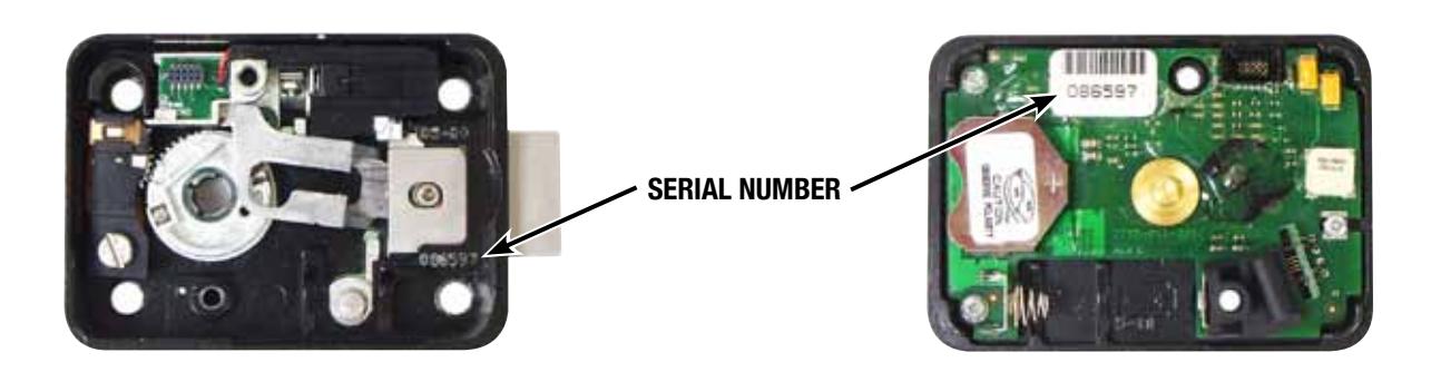
To recover from a lost or unknown combination, you will need the six-digit serial number stamped into the lock case below the bolt and on the circuit board located on the inside of the cover (see photographs below). Divide the serial number into three two-digit numbers. This will be your recovery combination. You will also need to make up a new operating combination, as the recovery process requires you to enter a new operating combination. The unknown combination function is activated by pressing the setup module button for one second when the LED next to the unknown code icon is blinking. When this function is selected, the red and yellow LEDs will blink and the lock will beep six times.
- 1. Turn the dial left (counterclockwise) at least four complete revolutions, then stop precisely on the first number of the recovery combination.
- 2. Turn the dial right (clockwise), stopping the third time the second recovery combination number comes to the opening index.
-
3. Turn the dial left, stopping the second time the third recovery combination number comes to the opening index. Then turn the dial right about ten numbers.
- The lock will emit three quick beeps if the recovery combination has been entered correctly. It will emit a single long error tone and the red error LED will light if the recovery combination is not recognized. If this happens, you need to re-check the lock serial number.
- 4. Turn the dial left (counterclockwise) at least four complete revolutions, then stop when the first number of the new operating combination comes to the opening index.
- 5. Turn the dial right (clockwise), stopping the third time the second new operating combination number comes to the opening index.
- 6. Turn the dial left, stopping the second time the third new operating combination number comes to the opening index. The lock will emit three quick beeps.
- 7. Turn the dial left (counterclockwise) at least four complete revolutions, then stop when the first number of the new operating combination comes to the opening index.
- 8. Turn the dial right (clockwise), stopping the third time the second new operating combination number comes to the opening index.
- 9. Turn the dial left, stopping the second time the third new operating combination number comes to the opening index.
- 10. Turn the dial right about ten numbers. The lock will emit five quick beeps, indicating a successful combination change, and the green LED will light for two seconds. If you continue turning the dial to the right, the lock bolt will retract.
The setup module will then turn itself off. To turn it back on to perform other functions, press the button. If the lock had been in dual user mode, the 2nd combination is automatically deleted and the lock is set to single user mode. Press the module button to turn it back on if further lock programming is required.
S&G© Model 2740 Electromechanical Safe Lock
Latch Open Function

This function is not available on a setup module with a yellow front.
When the lock batteries MUST be replaced, the lock will open, but will not re-lock. To recover from this condition, use the latch open function. The latch open function is activated by pressing the setup module button for one second when the LED next to the latch open icon is blinking. When this function is selected, the red and yellow LEDs will blink. If the latch open function did not work, the red error LED will light for two seconds, and you can try again. If the latch open function was successful, the green LED will light for two seconds, and the module will turn itself off. Immediately turn the dial to extend the lock bolt with the safe or container door OPEN . Remove the lock cover and replace BOTH batteries following the battery replacement procedure beginning on page 13 of this manual. Re-install the cover, then test the lock function with the container OPEN . You should operate the lock successfully at least three times before closing the container .
Calibration Function
The lock must be calibrated both clockwise and counterclockwise immediately following installation. If the lock has never been calibrated, a beep pattern (three beeps - pause - three beeps - pause - three beeps) will sound whenever the dial is turned. Calibration requires you to dial precisely to zero. If you pass zero, even by a fraction of a number, when you meant to stop on it, continue dialing in the same direction to reach zero again. You will dial to zero at least three times, pressing the module button each time.
The calibration function is activated by pressing the setup module button for one second when the LED adjacent to the calibrate/clockwise icon ( ) is blinking. The red and yellow LEDs will flash. Within twenty seconds, turn the dial right (clockwise) at least one full revolution, then stop precisely on zero. With the dial exactly on zero, press the module button. The green LED will light for ½ second. Again, within twenty seconds, turn the dial right precisely to zero, then press the module button. The green LED will light for ½ second. Once again, within twenty seconds, turn the dial right precisely to zero, then press the module button. The green LED will light for ½ second. You may have to dial right to zero more than three times for the lock to calibrate correctly. When the lock has successfully calibratred to zero and you press the module button, the green LED will light for two seconds, then the module will turn itself off.
The calibrate/counterclockwise function is activated by pressing the setup module button for one second when the LED adjacent to the calibrate/ counterclockwise ( ) is blinking. Press and hold the module button for one second. The yellow LED will flash. Within twenty seconds, begin the same calibration process, this time always turning the dial left (counterclockwise) to zero. Turn the dial left (counterclockwise) at least one full revolution, then stop precisely on zero. With the dial exactly on zero, press the module button. The green LED will light for ½ second. Again, within twenty seconds, turn the dial left precisely to zero, then press the module button. The green LED will light for ½ second. Once again, within twenty seconds, turn the dial left precisely to zero, then press the module button. The green LED will light for ½ second. You may have to dial left to zero more than three times for the lock to calibrate correctly. When the lock has successfully calibratred to zero and you press the module button, the green LED will light for two seconds, then the module will turn itself off. To turn it back on, press the button.
If the lock cannot confirm proper calibration, it will continue to wait for you to turn the dial and press the setup module button at zero. If you cease all activity for several seconds, the setup module will "time out," and you will need to press the button to re-activate it and begin the calibration process all over again.
S&G suggests that the 2740 lock be calibrated whenever batteries are changed. This will compensate for small movements in the dial ring that may occur from moving a container or from something bumping the dial or ring. It's equivalent to re-setting a mechanical lock's combination whenever service is performed.
Verify that the combination(s) will still open the lock after dial re-calibration has been completed. If a combination had been set while the dial calibration was slightly off, then re-calibrating the dial may cause the existing combination to be a little off.
Note: When the setup module is disconnected from the lock, a beep will sound, indicating that the new calibration values have been stored in the lock's memory.
Setup Module Instructions and Beep Patterns
S&G© Model 2740 Electromechanical Safe Lock
Beep Patterns
Beep Pattern Identification Table
The 2740 lock provides information to the user in the form of audible beeps. There are two kinds of beeps—a short, distinct beep and a long beep that is ten times as long as the standard beep. We refer to the long beep as a brap .
The following table identifies all of the beep patterns the 2740 lock can emit and what they mean. Note that some beep signals can mean more than one thing, depending on what operation is being performed.
| Beep Pattern | Description |
|---|---|
| 1 beep | change key has been inserted and recognized |
| 1 beep | in the change operating mode, sounded to indicate single user is selected |
| 2 beeps | in the change operating mode, sounded to indicate dual user is selected |
| 3 beeps | sounded between each step of a programming sequence |
| 4 beeps | sounded after the first combination is successfully entered in dual control mode |
| 5 beeps | sounded when a change combination, change operating mode, or code recovery procedure is completed |
| 6 beeps | sounded when the lock enters a state to change the operating mode |
| 10 beeps | sounded whenever the lock is opened to indicate low battery condition (repeats periodically) |
| 3 beeps/pause/3 beeps/pause/3 beeps | sounded when the lock has never been calibrated and needs calibration |
| 1 brap (long beep) | sounded when an error occurs in a programming sequence |
| 2 braps (long beeeps) | sounded when the dial is turned while the lock is in a ten minute penalty time |
Battery Changing Instructions
S&G© Model 2740 Electromechanical Safe Lock
Low Battery Condition
The S&G© 2740 Model Electromechanical Safe Lock is powered by a main battery (CR123A lithium camera-type), and also houses a long-life backup battery (CR2450 coin cell). Both batteries are on the underside of the lock cover.
Battery condition should be routinely checked whenever the setup module is connected to the lock. In addition, the lock will emit ten beeps whenever it is opened and the batteries need to be replaced. The ten beeps will repeat every twenty seconds for one minute after the lock is opened. If the low battery signal is ignored, the lock will eventually latch open. This means the lock bolt remains retracted after an opening, and it will not extend again. The latch-open state can only be released by use of a setup module.
Battery Replacement Procedure
Both batteries must be replaced at the same time. Battery changes should only be performed by a technician certified by S&G to work on this product.
The lock will NOT forget your code(s) during battery change. The circuitry is designed to hold this information for extended periods of time even if there are no batteries installed. Codes are stored in non-volatile memory.
It is recommended that you wear the included grounded wrist strap throughout the entire battery changing operation. The strap should be connected to a bare metal surface of the safe (container) before the lock cover is removed.
Step 1 —Extend the lock bolt. If the lock is in latch-open condition, this will require a setup module (see page 11).
Step 2 —Remove the two lock cover screws, and carefully pull the cover off of the lock. Do not touch the underside of the cover with any tools. Battery replacement should be done with fingers only. Handle the cover by its edges whenever possible.
Step 3 —Remove the CR123A camera-type battery first. If you pull the battery against the spring on the negative contact (compressing the spring), the positive end of the battery can then be pulled up and the battery easily removed. Next, remove the CR2450 coin cell battery, sliding it out of its housing. Wait at least one minute so that internal capacitors can drain.
Battery Changing Instructions
S&G© Model 2740 Electromechanical Safe Lock
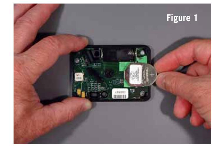
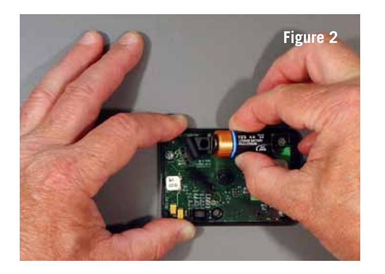
Step 4 —Slide a new coin cell battery into its housing first, positive side up (figure 1). Then install the camera-type battery into its receptacle (figure 2). Never force batteries into place. If batteries are installed backwards, no electrical damage will occur, but the lock will not work as designed, or at all. If you find that you have inadvertently installed the coin cell battery backwards (reverse polarity), discard the battery in favor of a new one. It is easy to temporarily short this type of battery by installing it incorrectly, significantly depleting its power.
When the backup battery (coin cell) and then the main battery (camera-type) are installed, you will hear a beep. If you have not waited one minute between removal of the old batteries and installation of the new ones, the beep may not occur. If you do not hear the beep, remove both batteries and repeat the installation process, inserting the coin cell battery first.
Ten seconds after the beep, the lock will perform a battery check. You will hear a single beep if the ten-second battery check is successful. It is recommended that you wait for the beep before installing the cover onto the lock.
If the lock determines that one or both batteries are not fresh, there will be no beep. You should then remove both batteries for at least one minute, then re-install them beginning with step 3. If you still do not hear the battery confirmation beep at the end of the ten-second battery check, replace both batteries with new ones.
If the lock cannot confirm good batteries and the lock is subsequently opened, it will go into the lock open state, forcing you to install fresh batteries.
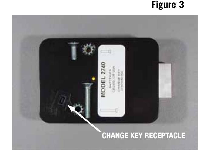
Step 5 —Re-install the lock cover using both cover screws. The longer cover screw goes in the screw hole closest to the change key receptacle (figure 3). The lock may emit one long beep.
Step 6 —The setup module should be attached to the lock to verify the condition of the new batteries.
Step 7 —After verifying that the new batteries are good, disconnect the setup module and WITH THE CONTAINER DOOR OR DRAWER OPEN, verify that the operating combination(s) do indeed open the lock. Check proper operation of the combination(s) a minimum of three times.
WARRANTY
Seller warrants that for one year from the date of shipment from Seller's point of manufacture, the goods shall be free from defects in material and workmanship, provided the goods are normally and properly used according to the Seller's written instructions.
THIS WARRANTY IS EXPRESSLY MADE IN LIEU OF ANY AND ALL OTHER WARRANTIES, EXPRESS OR IMPLIED. S&G DOES NOT WARRANT THAT THE GOODS ARE MERCHANTABLE OR FIT FOR ANY PARTICULAR PURPOSE EXCEPT AS EXPRESSLY PROVIDED HEREIN.
Seller's entire liability and Buyer's exclusive remedy in the event that the goods do not conform to the foregoing warranty shall be Seller's repair or replacement of the goods (including payment of freight costs to and from point of manufacture).
UNAUTHORIZED USE OF DIAL, DIAL RINGS, AND/OR SPINDLES NOT MANUFACTURED BY THE SELLER IN CONJUNCTION WITH ITS COMBINATION LOCK PRODUCTS INVALIDATES THE WARRANTY.
SELLER SHALL HAVE NO LIABILITY FOR ANY CONSEQUENTIAL, INCIDENTAL, INDIRECT OR SPECIAL DAMAGES. SELLER DOES NOT WARRANT ITS LOCK PRODUCTS TO BE IMPERVIOUS TO FORCIBLE OR SURREPTITIOUS ENTRY, AND SELLER SHALL HAVE NO LIABILITY FOR DAMAGE TO OR LOSS OF PROPERTY SOUGHT TO BE PROTECTED BY ANY SUCH LOCK.