Sargent-Greenleaf-Electronic-Safe-Lock-Electromechanical-Government-Security-Lock-SG2740A-Installation
Open the original PDF document
View PDFModel 2740 High Security Safe Lock
Installation Instructions

Mounting Considerations:
- This lock requires setup and adjustment with the use of a setup module after installation. The installation cannot be completed without the use of a setup module. Setup modules are only issued to S&G Certified Technicians who have sucessfully completed specialized training on the 2740 lock.
- The Sargent & Greenleaf 2740 safe lock is designed to use the same mounting screw locations as common S&G mechanical and electronic safe locks. In most instances it can easily be mounted in place of these locks.

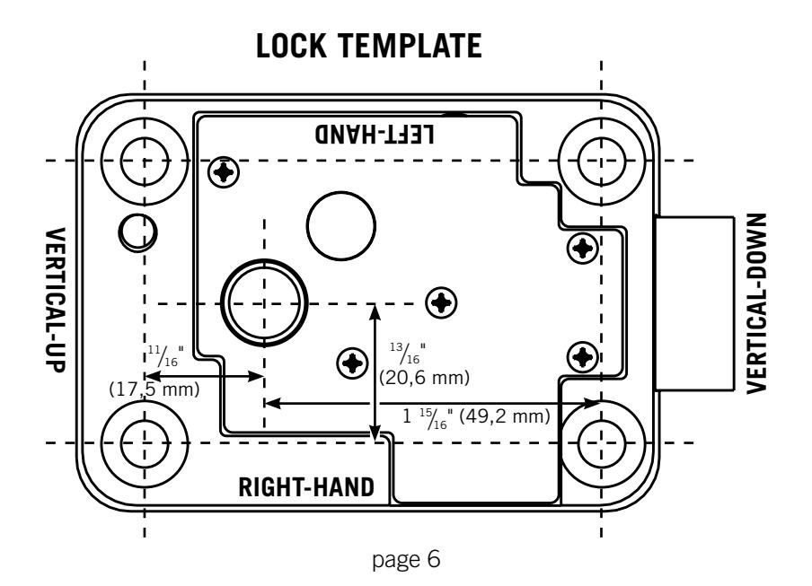
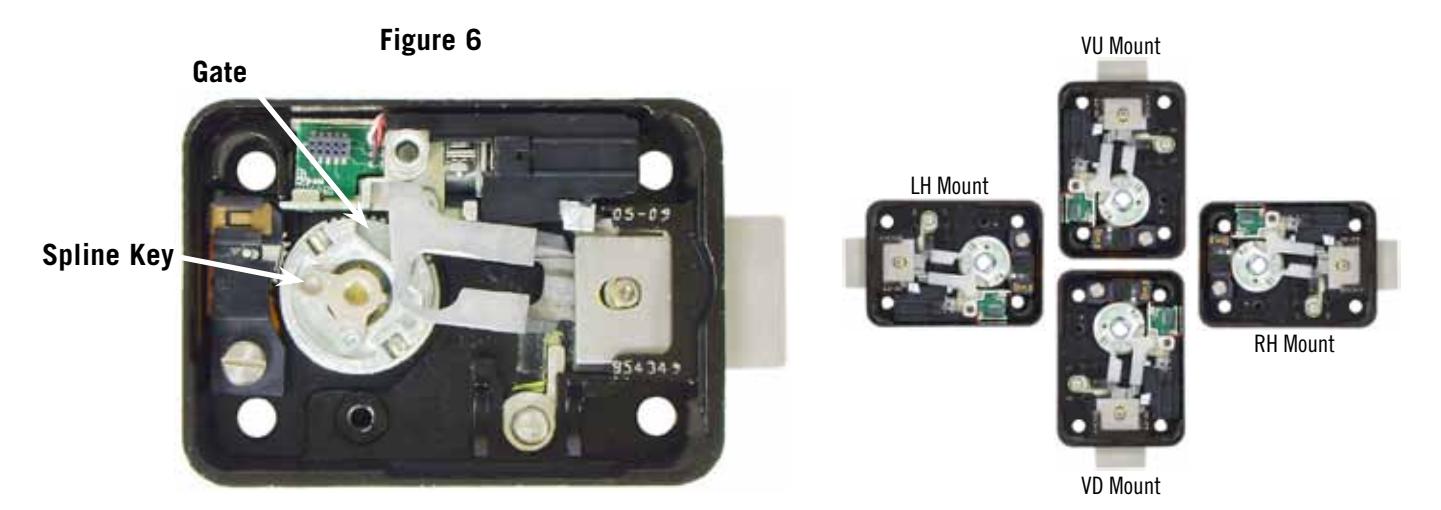
- The 2740 accommodates right-hand, left-hand, vertical-up and vertical-down mounting applications. A single model can be splined for any of these applications during the installation process.
- The dial ring diameter is approximately 3 ¾ inches, matching the diameter of the majority of S&G dial rings.
- Each 2740 lock and cover is configured to work together. If installing multiple locks, be very careful to avoid using a cover with any lock other than the one with which it was shipped from S&G's factory.
- Each 2740 lock requires one CR2450 coin cell battery and one CR123A lithium camera-type battery. Any time one battery is replaced, the other should be replaced. Fresh batteries should be included with your lock. If not, be careful to avoid using partially drained batteries.
- Modifications to the lock are not recommended and will void the manufacturer's warranty.
- Personal information that can be directly related to a combination holder, such as a birth date, street number, or phone number, should not be used in creating a lock code. Avoid combinations that could be easily guessed. Be sure to change the combination from the factory setting 50-25-50 to one of your own choosing.
- The S&G 2740 is warranted against defects in materials and workmanship. This warranty applies only to locks installed and set up by an S&G certified technician.
Sargent & Greenleaf, Inc.
A Wholly Owned Subsidiary of Stanley Security Solutions, Inc. PO Box 930, Nicholasville, Kentucky 40340-0930 USA Phone (859) 885-9411 Phone (800) 826-7652 FAX (859) 887-2057 FAX (800) 634-4843
Sargent & Greenleaf S.A.
9, chemin du Croset 1024 Ecublens, Switzerland Phone +41-21 694 34 00 FAX +41-21 694 34 09
Installation Notes
The Sargent & Greenleaf model 2740 lock was designed to meet Federal Specification FF-L-2740A. It can be retrofit to most security containers currently in service.
It is necessary to remove only the lock cover for installation. All other parts should remain in place as received from the manufacturer.
Most safes and cabinets will already be prepped for lock installation. In the unlikely event that this is not the case, locate exact position you want for the lock on the mounting plate. Using the template on the last page of these instructions, drill and tap four holes for the attaching screws ( " X 20 or M6 for metric applications). Using the template, drill a hole for the spindle through the mounting plate. The minimum spindle hole diameter is " (9,5 mm). The optimum hole size is " (12,7 mm) diameter.
Wear the included static discharge wrist strap whenever you are about to remove the lock cover, or whenever the cover is off of the lock body. The strap should be grounded to any bare metal of the safe (container).
It is necessary to remove only the cover when attaching the lock. All other parts should remain in place as received from the factory. When the cover is off of the lock, handle it carefully. It houses the microprocessor and related circuitry. Do not touch the circuit board.
INSTALLATION INSTRUCTIONS
1. Make sure the lock bolt is in the extended position (Figure 1). Carefully remove the lock cover.
CAUTION: Handle the cover by its edges. Do not touch the circuit board or pin towers. Any inadvertent contact may introduce a static discharge which will damage the electronics. Static discharge may cause immediate lock failure or delayed failure.
CAUTION: Do not attempt to remove the drive cam or the lever.
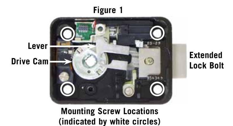
- 2. Mount the lock body in place with four X 20 attaching screws provided (Figure 1). Apply one drop of Loctite 242® threadlocker to the threads of each mounting screw near the tip. No Loctite should be allowed to contaminate the inside of the lock case.
- 3. Attach the dial ring to the front of the safe or cabinet by loosely installing the attaching screws to hold the dial ring in place for alignment. The dial ring opening index should be at the 12 o'clock center position (Figure 3).
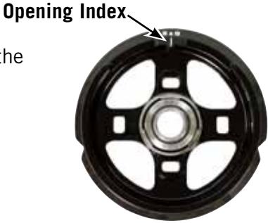
Figure 3
- 4. Slide the dial spring over the spindle hub at the base of the spindle. Place the metal dial washer on top of the spring, then the white washer on top of the metal washer, as shown in the photo to the right.
- 5. Hold the drive cam in place in the lock case with one hand and thread the dial/spindle assembly into the cam until the dial's edge is flush with the top of the dial ring (Figure 4, far right) or until the dial stops. Make sure the flat washer and spring stay in

6. The alignment of the dial and ring is important to the proper operation of the lock. Very good alignment must be obtained. The dial should be flush and centered with the top surface of the dial ring for true centering (Figure 4). When the dial ring is as perfectely aligned as possible, use masking tape to hold it in position. Use several pieces of tape to make sure it doesn't move out of alignment.
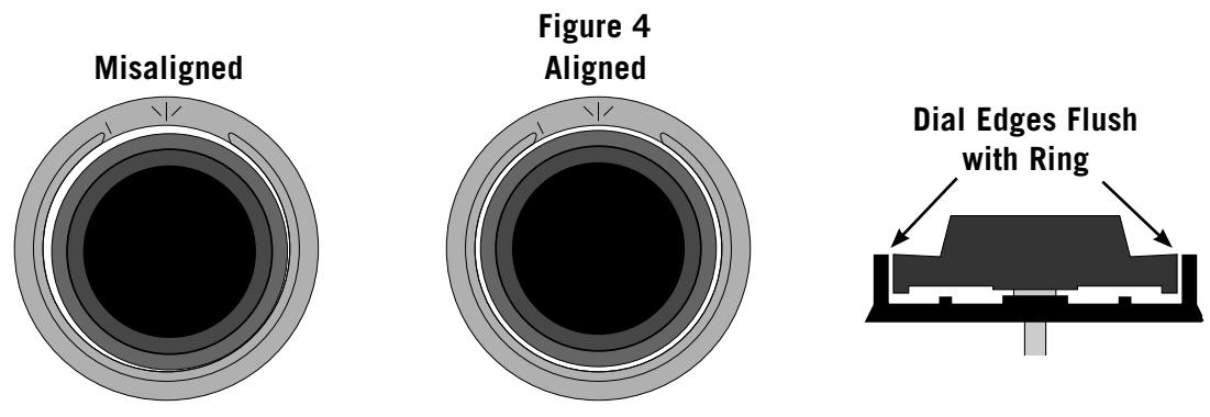
Note that the small gap between the dial and ring is uneven when the dial ring is misaligned, but is even when the dial ring is properly aligned. The center of a properly aligned dial ring is in perfect alignment with the center of the spindle hole in the drive cam.
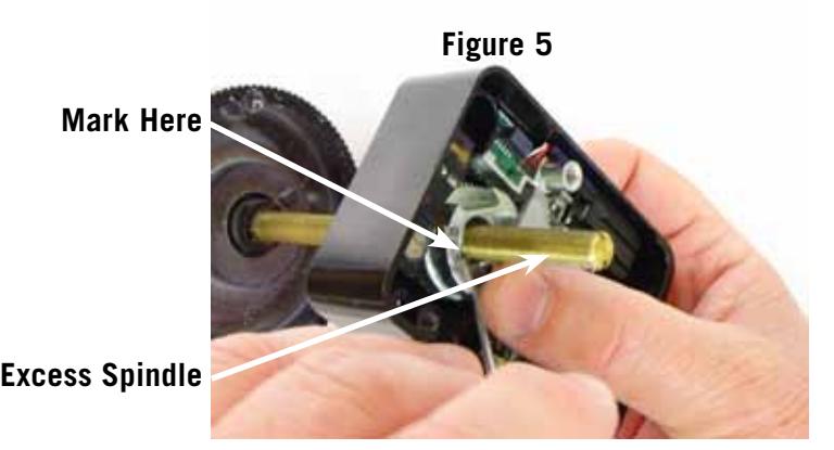
7. Measure and/or mark the excess spindle that projects beyond the recessed inner surface of the drive cam (Figure 5). When the spindle is cut to length, it can be as much as two threads short of flush with the surface of the drive cam, but it cannot extend beyond flush.
- 8. Remove the dial without moving the dial ring out alignment. Remove one dial ring screw, apply a drop of Locktite® 242 threadlocker to the threads near the tip, re-install the screw, and tighten firmly. Do the same with the remaining screw. Remove the masking tape used to temporarily hold the ring in alignment.
- 9. Remove the spring and washers from the dial. Cut off the excess spindle where you marked it, and remove any burrs from the end. You may also find that the spindle threads more easily into the drive cam if you bevel the end of the freshly cut spindle slightly. Do not discard the excess spindle piece as you may use it to seat the spline key later in the installation.
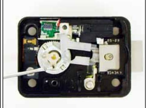
- 10. With the dial spring and flat washer in place, insert the dial into the lock. Hold the drive cam in place, positioned for its gate (Figure 6) to receive the fence of the lever assembly, and thread the dial into the cam until the top of the dial is flush with the top surface of the dial ring (Figure 4, far right) or until the dial stops.
- 11. Turn the dial counterclockwise until zero is aligned with the opening index of the dial ring. If it was necessary to turn the dial less than ½ turn, back it out of the drive cam one additional revolution. The proper spindle spline keyway and drive cam spline keyway should now be closely aligned.
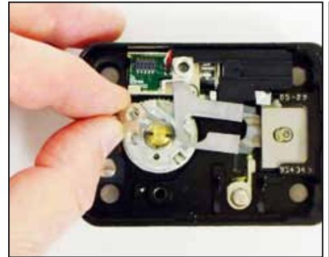
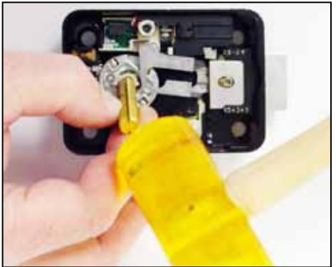
12. After the spline keyways are aligned, insert the spline key as far as you can with your fingers (sequence in Figure 7). Make sure the spline key is oriented to fit into the recess in the cam. It will only fit properly one way. The spindle and cam are now correctly splined for the way the lock is mounted (RH, LH, VU, or VD). Use a pin punch or the piece of excess spindle you cut off in Step 9 to carefully tap the spline key until its underside just touches the top surface of the drive cam. Be very careful to avoid striking anything other than the spline key. With the spline key fully seated, the dial must turn freely with no rubbing or interference. Once the spline key is seated, install the included 2-56 spline key screw firmly, but do not overtighten. If desired, you can carefully apply a very small amount (much less than a drop) of Loctite® 242 threadlocker to the screw threads near the tip before installing it.
Figure 7
Note: You can easily remove the spline key after removing the 2-56 screw by threading the longer of the lock's two cover screws into the center of the spline key. As you turn the screw into the spline key, the key will be extracted. This spline key is reusable.
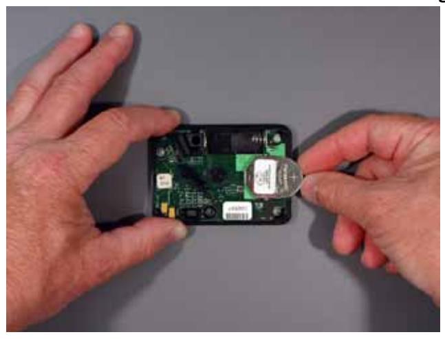
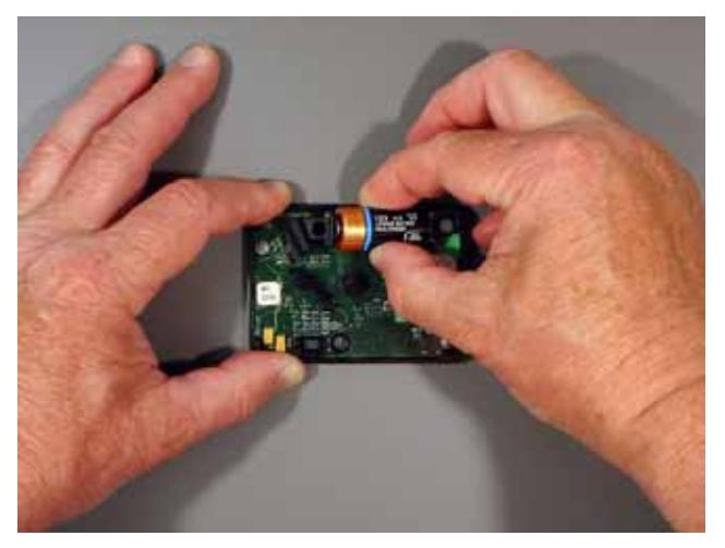
13. Install the two batteries in the underside of the cover (Figure 8). The circular coin cell battery goes in first, positive side up. Then the camera-type battery is inserted as shown. When the coin cell battery and then the main battery are installed, you will hear a beep. If you do not hear the beep, remove both batteries for one minute, then repeat the installation process. Always insert the coin cell battery first then the camera-type battery. Ten seconds after the batteries are installed, the lock does a battery check. If the battery check passes, another beep will be heard. If not, remove both batteries for one minue, then repeat the battery installation process. If the second battery installation does not produce the two beeps, repeat the battery installation process using new batteries.
Figure 8
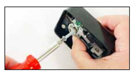
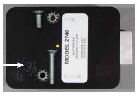
14. Place the cover on the lock body, and fasten with the two screws provided. The longer screw goes in the cover screw opening closest to the change key receptacle (Figure 9). Tighten securely.
Figure 9
Change Key Receptacle
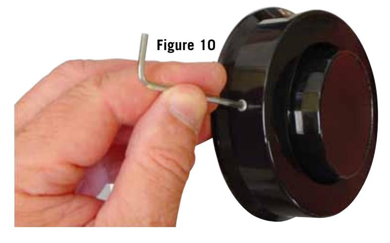
15. The Spy-Proof ® dial cover is attached to the dial ring at two points (Figure 10), one on each side of the dial ring. The cover is attached using a 4-40 socket head cap screw (requiring a 3/32" hex driver) at each of the two locations. Put one small drop of Loctite 242® threadlocker on the tip of each cap screw before installing. The cover does not need to be removed for combination changing. The Spy-Proof® cover must be installed for the lock to meet Federal Specifications.
- 16. Again, check to make sure the dial turns freely.
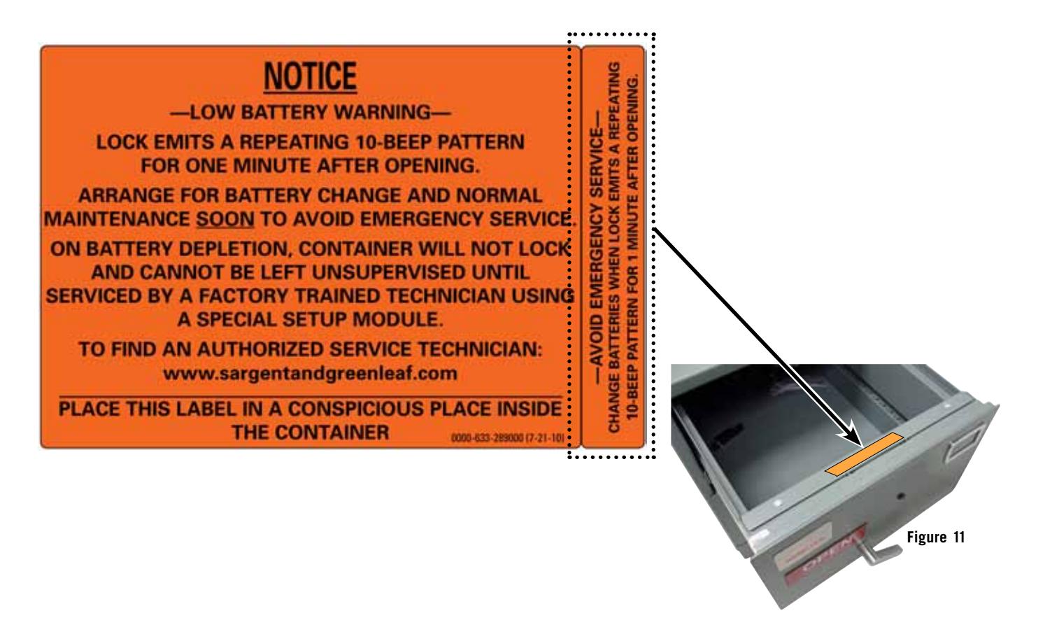
- 17. Place the self-adhesive orange label inside the safe or container, where it is readily visible when the door or locking drawer is open. For instance, the locking drawer's inside cover is a good location. There is also a 5/8" wide label on the same sheet that is sized to fit on the top surface of file drawer back plates (Figure 11), where it will be in plain view of anyone who opens the drawer.
The lock installation is complete. Refer to the operating instructions for calibration and combination setting procedures. The installation is not complete until the lock is calibrated.