Sargent & Greenleaf Electronic Safe Lock Electromechanical Government Security Lock SG2740 Overly Door Retrofit
Open the original PDF document
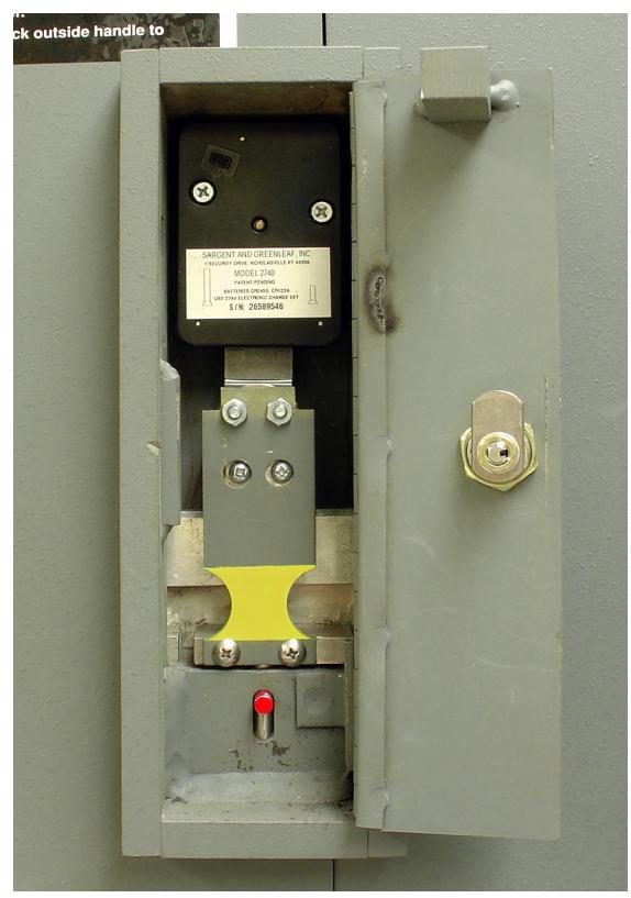
View PDFModel 2740 High Security Safe Lock
Overly Class 5 Escape Device Retrofit Instructions (use S&G retrofit kit 2740-117)

First Things First:
- The procedures described in this document are intended for skilled, experienced safe technicians and locksmiths. They are not intended for those who are unfamiliar with the inner workings of lock mechanisms and vault doors.
- These instructions show installation of a Sargent & Greenleaf model 2740 lock on an Overly Class 5 red label vault door that incorporates an inside emergency release, also known as an escape device . The parts necessary for the installation are found in an S&G model 2740-117 retrofit kit. This kit does NOT include the lock which can be ordered under S&G part number 2740-100.
- This lock requires calibration with the use of a 2740 setup module after reassembly and installation on a door. The installation cannot be completed without the use of a setup module (S&G part number 2740-200).
- Lock installation requires the model 2740 operating instructions (document 630-746). This document is packaged with the 2740-100 lock. If they have been removed, you can obtain an electronic copy at www.sargentandgreenleaf.com.
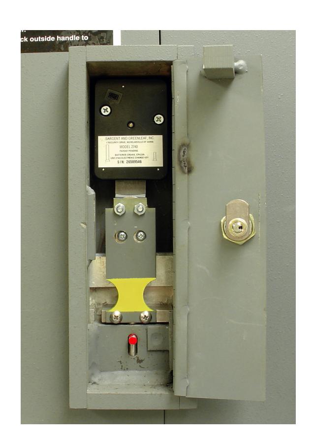
- It is not necessary or recommended that you remove any 2740 lock body internal components. Installation only requires removal of the lock's cover.
- Failure to follow these instructions and use the approved 2740-117 retrofit kit can lead to a vault lockout. In this event, the lock is not covered under S&G's warranty. The 2740-117 retrofit kit is only for use with S&G locks.
Sargent & Greenleaf, Inc.
A Wholly Owned Subsidiary of Stanley Security Solutions, Inc. PO Box 930, Nicholasville, Kentucky 40340-0930 USA Phone (859) 885-9411 Phone (800) 826-7652 FAX (859) 887-2057 FAX (800) 634-4843
Sargent & Greenleaf S.A.
9, chemin du Croset 1024 Ecublens, Switzerland Phone +41-21 694 34 00 FAX +41-21 694 34 09
Step 1: If there is a lock present on the vault door, remove it completely, and detach the escape device assembly by removing the two 10-32 screws that hold it to the end of the lock bolt. These screws can be discarded.
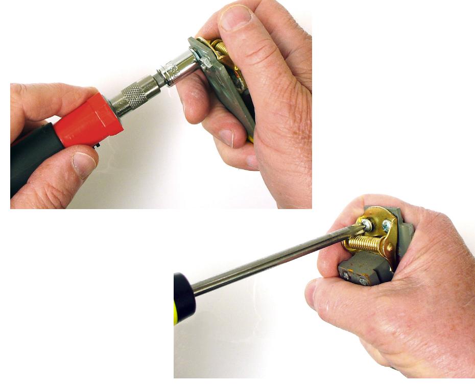
Step 2: Remove the L-bracket from the escape device by removing the two 8-32 screws that secure it to the hinge block. The L-bracket can be discarded. The screws will be used later to fasten a new L-bracket to the hinge block.
Step 3: Using an 11/32" nut driver or wrench, remove the hinge nuts from the long, flat handle bracket. Once these are out, remove the two 8-32 screws from the opposite side of the hinge. Now the old hinge (with hinge block still attached) can be separated from the handle bracket. These screws and nuts will be re-used, so it's a good idea to wire brush the threads to clean out any dried threadlocker.
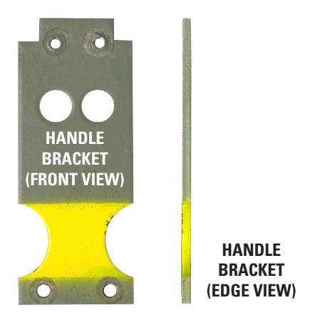
Step 4: Inspect the long handle bracket to make sure it is straight and flat. Sometimes these brackets are bent as a crude form of installation adjustment. This is not recommended. The handle bracket must be flat and straight to work with the 2740-117 retrofit kit. Flatten and/or straighten as necessary.
Note that the large steel block (Overly refers to it as the "ANTI-DRIVE STRIKE") has been removed from the handle bracket in the photos at right. It is only necessary to remove the block if the handle bracket needs to be flattened or straightened.
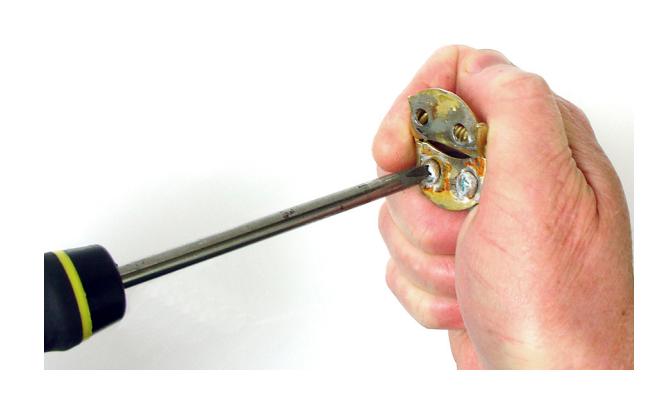
Step 5: Remove the two 8-32 screws that hold the old hinge to the hinge block. These screws will be re-used, so it's a good idea to wire brush the threads to clean out any dried threadlocker. It's likely you'll need to pry the hinge leaf away from the steel block to separate the two pieces after the screws have been removed. You can discard the old hinge.
Note: Whenever installing machine screws or nuts, use a drop of Loctite 242® threadlocker on the screw threads. A tube of threadlocker is included in the 2740-117 retrofit kit.
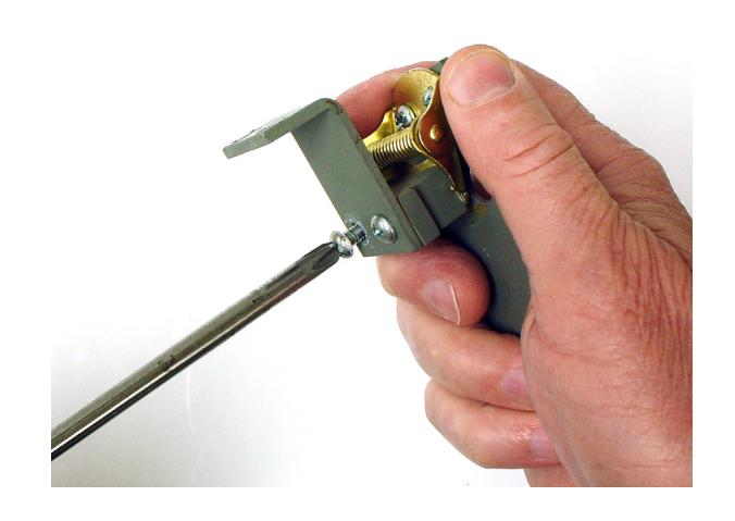
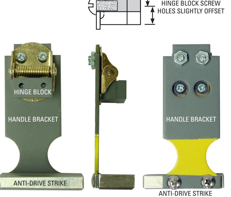
Step 6: Install the new hinge found in the retrofit kit to the steel hinge block. It doesn't make any difference which leaf of the spring is attached to the block. However, the screw holes in the hinge block are slightly offset. Orient the spring with the block's screw holes oriented as shown at right. Use the screws you removed in step 5.
Step 7: Install the other end of the spring assembly to the handle bracket by reversing the process in step 3. The screws go through the spring leaf, then through the handle bracket until tight. Now the nuts can be installed tightly on the exposed screw threads. Be sure to use a drop or two of threadlocker on the screw threads.
When finished with steps 6 and 7, you should have an assembly that looks like the one pictured in three views at the right.
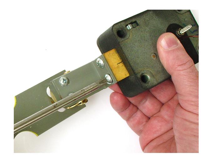
Step 8: Using the two new 10-32 screws provided in the retrofit kit, attach the black L-bracket to the end of the 2740 lock bolt as shown at right. Align the top edge of the bracket's short end with the top surface of the lock bolt. Don't use threadlocker on these screws at this time.
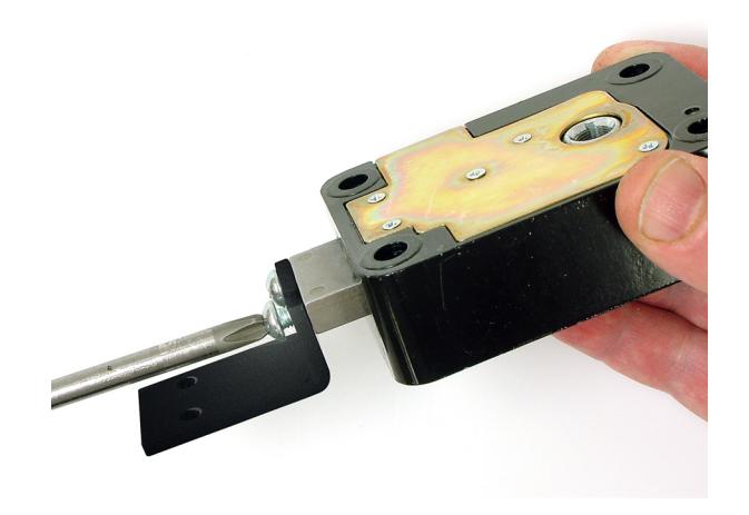
Step 9: Use the remaining two 8-32 screws to attach the escape device assembly to the L-bracket as shown at right. Use a drop of threadlocker on the threads of each screw and tighten securely.
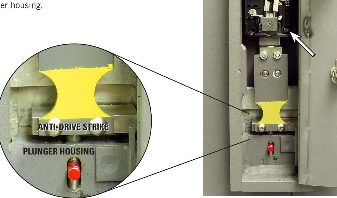
Step 10: Temporarily mount the lock body (with attached escape device) to the vault door. For now, it's only necessary to use two diagonally positioned 1/4-20 screws (see arrows at right). Note the gap between the bottom of the anti-drive strike and the top surface of the plunger housing.
page 4
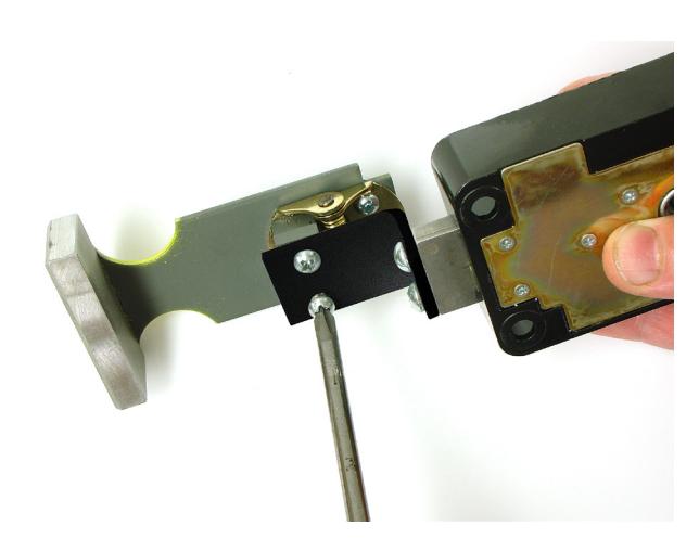
Step 11: There are five 0.032" thick spacers, or shims, in the 2740-117 retrofit kit. Stack and fit as many as you can (without forcing anything) between the bottom of the anti-drive strike and the top surface of the plunger housing. In this example, we can fit three stacked shims.
SEE HOW MANY SHIMS CAN BE STACKED ONE ON TOP OF THE OTHER HERE
Step 12: Subtract one shim from the stack that you could fit between the bottom of the anti-drive strike and the top surface of the plunger housing. Unfasten the L-bracket from the lock bolt, insert the remaining shims from your stack between the end of the lock bolt and the L-bracket, and re-attach the bracket to the end of the lock bolt. Use a drop of threadlocker on the threads of each screw. Tighten securely. In the installation pictured here, we were able to initially fit a stack of three shims between the anti-drive strike and the plunger housing, so we installed two shims between the L-bracket and lock bolt.
INSTALL THE SHIMS (STACK FROM STEP 11 MINUS 1) HERE
Step 13: Mount the lock body to the vault door as you did in step 10. The escape device should be in a straight line with the lock body, and there should be a slight gap between the bottom of the anti-drive strike and the top surface of the plunger housing. Those two surfaces should NOT be touching.
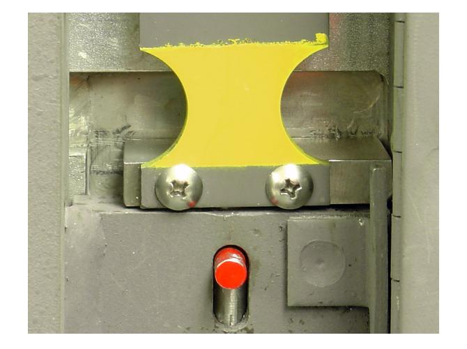
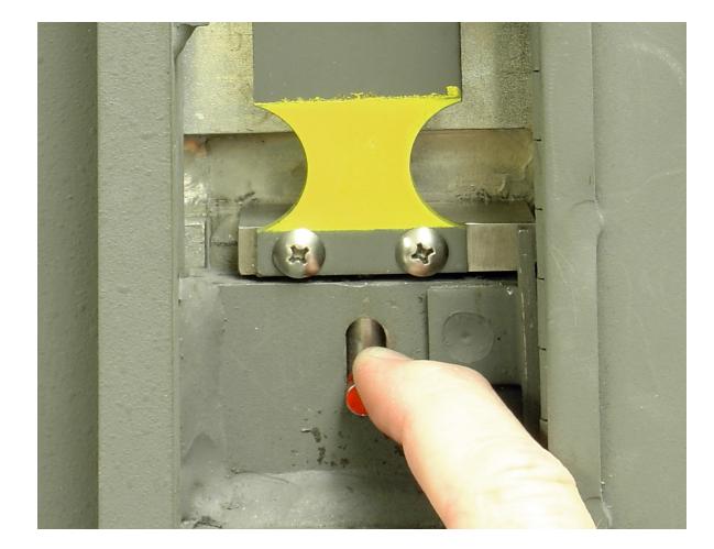
Step 14: Pull down the plunger and release it a few times to make sure it doesn't create movement in the escape device assembly as it operates. In particular, the end of the plunger cannot be allowed to push the escape device assembly upward by even a small amount. If so, remove one more shim from between the L-bracket and lock bolt.
Step 15: Complete the lock installation and calibration according to the instructions packaged with the 2740 lock. If they are missing, you can obtain a copy in PDF format online:
www.sargentandgreenleaf.com
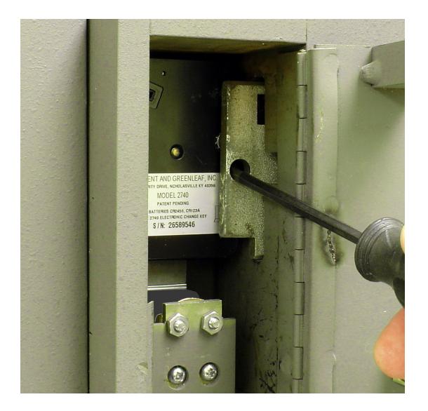
Step 16: Check the vault door by completing a minimum of three complete locking and unlocking cycles with the door OPEN. You may also wish to check it by actually closing and locking the door with an assistant inside the vault in case of trouble. When you are satisfied that the lock and escape device are working properly with no binding, slide the hardplate that protects the back of the lock into place by using the tip of a screwdriver in one of the holes provided. Close and lock the access door, and place the access door key in its holder on the inside of the vault door.
Be sure to instruct the vault custodian in the proper operation of the lock and the escape device.
The installation is complete.